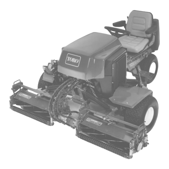
Toro Reelmaster 2300-D Service Manual
Hide thumbs
Also See for Reelmaster 2300-D:
- Operator's manual (44 pages) ,
- Operator's manual (29 pages)
Advertisement
Quick Links
Preface
The purpose of this publication is to provide the service
technician with information for troubleshooting, testing,
and repair of major systems and components on the
Reelmaster 2300–D/2600–D.
REFER TO THE TRACTION UNIT AND CUTTING
UNIT OPERATOR'S MANUALS FOR OPERATING,
MAINTENANCE AND
TIONS. Space is provided in Chapter 2 of this book to
insert the Operator's Manuals and Parts Catalogs for
your machine. Replacement Operator's Manuals are
available by sending complete Model and Serial Num-
ber to:
The Toro Company
8111 Lyndale Avenue South
Minneapolis, MN 55420
The Toro Company reserves the right to change product
specifications or this publication without notice.
Reelmaster 2300–D/2600–D
ADJUSTMENT
INSTRUC-
The Toro Company – 1996, 1998
This safety symbol means DANGER, WARN-
ING, or CAUTION, PERSONAL SAFETY
INSTRUCTION. When you see this symbol,
carefully read the instructions that follow.
Failure to obey the instructions may result in
personal injury.
NOTE: A NOTE will give general information about the
correct operation, maintenance, service, testing, or re-
pair of the machine.
IMPORTANT: The IMPORTANT notice will give im-
portant instructions which must be followed to pre-
vent damage to systems or components on the
machine.
Part No. 96876SL Rev. A
Service Manual
Advertisement
Chapters
Troubleshooting

Related Manuals for Toro Reelmaster 2300-D


Summary of Contents for Toro Reelmaster 2300-D
- Page 1 Minneapolis, MN 55420 portant instructions which must be followed to pre- vent damage to systems or components on the The Toro Company reserves the right to change product machine. specifications or this publication without notice. The Toro Company – 1996, 1998...
- Page 2 This page is blank.
-
Page 3: Table Of Contents
Table Of Contents Chapter 1 – Safety Special Tools ......4 – 16 Troubleshooting . - Page 4 This page is blank.
-
Page 5: Chapter 1 - Safety
Reduce the potential machine. If you have questions about this Service for any injury by complying with the following safety in- Manual, please contact: structions. The Toro Company Commercial Service Department 8111 Lyndale Avenue South WARNING Minneapolis, Minnesota 55420–1196 The engine exhaust contains carbon 2. - Page 6 5. Do not carry passengers on the machine. Keep ev- 9. Make sure the work area is clear of objects which eryone, especially children and pets, away from the ar- might be picked up and thrown by the reels. eas of operation. 10.
- Page 7 To assure safety and accuracy, have an Autho- 26. Before applying pressure to the hydraulic system, rized Toro Distributor check maximum engine speed make sure all hydraulic line connectors are tight and all with a tachometer.
-
Page 8: Safety And Instruction Decals
The following safety and instruction decals are affixed below and in your Parts Catalog. Order replacements to the traction unit. If any decal becomes illegible or from your Authorized Toro Distributor. damaged, install a new decal. Part numbers are listed ON LEFT SIDE OF SEAT PANEL (Part No. - Page 9 Reelmaster 2300–D/2600–D Safety Page 1 – 5...
- Page 10 Safety Reelmaster 2300–D/2600–D Page 1 – 6...
-
Page 11: Product Records
Chapter 2 Product Records and Manuals Table of Contents PRODUCT RECORDS ......1 TORQUE SPECIFICATIONS ....3 EQUIVALENTS AND CONVERSIONS . -
Page 12: Equivalents And Conversions
Equivalents and Conversions Product Records and Manuals Reelmaster 2300–D/2600–D Page 2 – 2... -
Page 13: Torque Specifications
Torque Specifications Reelmaster 2300–D/2600–D Product Records and Manuals Page 2 – 3... -
Page 14: Maintenance Interval Chart
Maintenance Interval Chart Product Records and Manuals Reelmaster 2300–D/2600–D Page 2 – 4... -
Page 15: Operation And Service History Report
Warranty Expires___________ Purchased From: _________________________ _________________________ _________________________ Contacts: Parts _________________________ Phone___________________ Service _________________________ Phone___________________ Sales _________________________ Phone___________________ See your TORO Distributor for other Publications, Manuals, and Videos from the TORO company. Reelmaster 2300–D/2600–D Product Records and Manuals Page 2 – 5... - Page 16 REELMASTER 2300–D/2600–D Maintenance Schedule Minimum Recommended Maintenance Intervals: Maintenance Procedure Maintenance Interval & Service Every Every Every 400hrs Every Inspect Air Filter, Dust Cup, and Baffle 200hrs 100hrs 50hrs Lubricate All Grease Fittings Change Engine Oil A–Level Check Fan and Alternator Belt Tensions Service Change Engine Oil and Filter B–Level...
- Page 17 REELMASTER 2300–D/2600–D Daily Maintenance Check List Unit Designation: ____________ Daily Maintenance: (duplicate this page for routine use) TORO ID #: ________–________ Daily Maintenance Check For Week Of ________________ Maintenance Maintenance TUES THURS Check Item ________HRS ________HRS ________HRS ________HRS ________HRS ________HRS...
- Page 18 Product Records and Manuals Reelmaster 2300–D/2600–D Page 2 – 8...
- Page 19 Chapter 3 Engine Table of Contents INTRODUCTION ......2 SERVICE AND REPAIRS .
-
Page 20: Introduction
Introduction This Chapter gives information about specifications, ever, the cost of the test equipment and the specialized maintenance, troubleshooting, testing, and repair of the nature of some repairs may dictate that the work be diesel engine used in the Reelmaster 2300–D/2600–D done at an engine repair facility. -
Page 21: Specifications
Specifications Item Description Make / Designation Perkins, vertical in–line, 4–stroke, water–cooled Diesel, 103–07 KL 70275 & KL 70372 Combustion Chamber IDI special swirl–combustion type Number of Cylinders Bore x Stroke mm (in.) 67 x 64 (2.64 x 2.52) Total Displacement cc (cu. in.) 676 (41.23) Compression Ratio 24:1... -
Page 22: Special Tools
Special Tools Order special tools from TORO SPECIAL TOOLS AND Some tools may be listed in the Reelmaster APPLICATIONS GUIDE (Commercial Products ). 2300–D/2600–D Parts Catalog. Tools may also be available from a local supplier. Filter Cleaner Mix with water and use solution to wash the Donaldson air cleaner element. - Page 23 Nozzle Test Adapter This adapter is required to test the fuel injection nozzles. Figure 4 Reelmaster 2300–D/2600–D Page 3 – 5 Engine...
-
Page 24: General Information
General Information Fuel Shutoff Valves These valves should be shut when removing the engine or placing the unit in long term storage. Figure 5 1. Fuel shut off (under the fuel tank) Figure 6 1. Fuel shut off valve (on the fuel filter) Engine Reelmaster 2300–D/2600–D Page 3 –... -
Page 25: Adjustments
Adjustments Alternator Belt 1. Gain access to the alternator belt (Fig 7). A. Loosen top hose clamp securing the upper por- tion of the hose connected to the air cleaner (8). B. Remove cap screws (1) and lock flange nuts (2). Remove hex head screws (3). -
Page 26: Throttle Linkage
Throttle Linkage 1. Verify high engine speed at 3200 50 RPM with the cold start button depressed. 2. If engine speed is out of specification, loosen cap screw, nut, and throttle cable clamp on the throttle cable bracket enough to allow the cable to slide freely within the bracket. -
Page 27: Service And Repairs
Service and Repairs Bleeding the Fuel System IMPORTANT: The fuel system must be primed when a new or rebuilt engine is started for the first time, if it runs out of fuel, or if maintenance is per- formed on the fuel system. 1. -
Page 28: Air Cleaner
Air Cleaner 1. Service the air cleaner filter every 400 hours (more frequently in extreme dusty or dirty conditions). Do not over service air filter. 2. Check air cleaner body (1) for damage which could possibly cause an air leak. Replace damaged air clean- er body. -
Page 29: Cleaning The Radiator And Screen
Cleaning the Radiator and Screen To prevent the engine from overheating, the radiator screen, radiator, and oil cooler must be kept clean. Check these components daily. If necessary, clean any debris off these parts. Clean these components more frequently in dusty dirty conditions. 1. -
Page 30: Changing The Engine Oil And Filter
Changing the Engine Oil and Filter Change oil and filter initially after the first 20 hours of op- eration. Thereafter, change oil every 50 hours and filter every 100 hours. 1. Position machine on a level surface. 2. Locate engine oil drain plug on the bottom of oil pan and place a collecting pan below it. -
Page 31: Engine Removal
Engine Removal 1. Park machine on a level surface, lower the cutting units, stop the engine, and remove the key from the start switch. Chock wheels to keep the machine from moving. 2. Disconnect positive (+) and then negative (–) bat- tery cables at the battery. - Page 32 RIGHT CONNECTED TO AIR FILTER HOSE 20 21 22 LH 46 RH LEFT FRONT Figure 19 1. Cap screw 17. U–bolt 32. Flat washer 2. Lock washer 18. Upper radiator hose 33. Lock washer 3. Clutch washer 19. Muffler clamp 34.
- Page 33 9. Close fuel shut–off valves under the fuel tank and on the fuel filter. 10. Disconnect hoses from engine (Fig. 19). A. Loosen upper hose clamp securing the air filter hose extending from the engine to the air cleaner. B. Loosen hose clamps (23). Disconnect upper ra- diator hose (18) and lower radiator hose (24) from the engine.
- Page 34 14. Disconnect electrical connections (Fig. 19). Note: Label all electrical leads for reassembly pur- poses. A. Disconnect connector with blue leads from the alternator. B. Disconnect connector with blue/white leads from the traction clutch. C. Disconnect connector from the front lift cylinder microswitch.
- Page 35 16. Remove traction pump drive belt as described in Traction (Electric) Clutch of the Service and Repairs section of Chapter 5 – Electrical System. 17. Remove engine (Fig. 19) A. Attach short section of chain between both lift tabs (1) located on each end of the cylinder head (2) (Fig.
-
Page 36: Engine Reinstallation
Engine Reinstallation 1. Make sure machine is parked on a level surface with E. On the right rear mount bracket (46), tighten cap screws (36). Torque cap screws from 34 to 42 ft–lb cutting units lowered, and key removed from the start switch. - Page 37 J. Reconnect gray, red, and white leads to the en- 11. Open fuel shut–off valves under the fuel tank and on gine starter solenoid located on below the exhaust the fuel filter. manifold. 12. Fill hydraulic reservoir with hydraulic fluid as de- K.
- Page 38 Engine Reelmaster 2300–D/2600–D Page 3 – 20...
- Page 39 Chapter 4 Hydraulic System Table of Contents SPECIFICATIONS ......2 TESTING ........19 GENERAL INFORMATION .
- Page 40 Specifications Item Description Traction Pump Variable displacement piston pump Maximum Operating Pressure 3000 PSI (207 bar) Maximum Intermittent Pressure 5000 PSI (345 bar) Maximum Rated Speed 3600 RPM Rated Flow @ Maximum Rated Speed and Pressure 17 GPM (64 LPM) Charge Pump Gerotor pump Maximum Operating Pressure...
-
Page 41: General Information
General Information Hydraulic Hoses Hydraulic hoses are subject to extreme conditions such as pressure differentials during operation and exposure to weather, sun, chemicals, very warm storage condi- WARNING tions, or mishandling during operation or maintenance. These conditions can cause damage or premature dete- rioration. - Page 42 SAE Straight Thread O–Ring Port – Non–adjustable 1. Make sure both threads and sealing surfaces are free of burrs, nicks, scratches, or any foreign material. 2. Always replace the O–ring seal when this type of fit- ting shows signs of leakage. O–Ring 3.
- Page 43 Boron OIl Eldoran UTH 4 to 6 gallons (15 to 22 liters) of hydraulic fluid. Order Exxon Torque Fluid Part No. 44–2500 from your Authorized Toro Distributor. Conoco Power–Tran 3 1. Position machine on a level surface. Make sure en- Kendall Hyken 052 gine is off and parking brake is set.
-
Page 44: Changing The Hydraulic System Fluid And Filter
200 hours of operation or yearly, whichever comes first. Use a genuine Toro oil filter for replacement. The hy- draulic fluid must be changed every 400 hours of opera- tion or yearly, whichever comes first. - Page 45 Hydraulic Schematic Reelmaster 2300–D/2600–D Page 4 – 7 Hydraulic System...
-
Page 46: Raise Cutting Units
Hydraulic Flow Diagrams Raise Cutting Units The charge pump is part of the traction pump and is di- lift cylinders. Hydraulic pressure against the cylinder rectly coupled to it. It supplies hydraulic pressure for pistons pushes the shafts out. At the same time, the pis- raising and lowering cutting units and maintaining 100 tons push the hydraulic fluid in the upper and inner por- to 150 PSI to the low pressure side of the traction circuit... - Page 47 Reelmaster 2300–D/2600–D Page 4 – 9 Hydraulic System...
-
Page 48: Traction Forward
Traction Forward The traction pump is driven by the engine through the A small amount of hydraulic oil leaves the traction circuit pulley, pump drive belt, and electric clutch. The traction through the bi–directional shuttle valve in the front left circuit of the hydraulic system acts essentially as a wheel motor. - Page 49 Reelmaster 2300–D/2600–D Page 4 – 11 Hydraulic System...
-
Page 50: Traction Reverse
Traction Reverse The traction circuit operates essentially the same in re- bottom port. However, oil flow to the rear wheel motor is verse as it does in the forward direction. However, the blocked by the check valve portion of the PC flow con- flow through the circuit is reversed and by–passes the troller and forced through the restriction before going to rear wheel motor. - Page 51 Reelmaster 2300–D/2600–D Page 4 – 13 Hydraulic System...
-
Page 52: Mow
The reel motor drive pump is directly coupled to the the tridge valve (LC1). The logic cartridge valve maintains traction pump which is driven directly by the engine a pressure differential of 75 PSI (5.2 bar) across the through the electric clutch. Taking its suction directly speed control valve. - Page 53 Reelmaster 2300–D/2600–D Page 4 – 15 Hydraulic System...
-
Page 54: Special Tools
Special Tools Order these tools from the TORO SPECIAL TOOLS Some tools may also be available from a local supplier. AND APPLICATIONS GUIDE (COMMERCIAL PROD- UCTS) . Hydraulic Pressure Test Kit Use to take various pressure readings for diagnostic tests. Quick disconnect fittings provided attach directly to mating fittings on machine test ports without tools. -
Page 55: Troubleshooting
Troubleshooting The cause of an improperly functioning hydraulic sys- Continued use of an improperly functioning hydraulic tem is best diagnosed with the use of proper testing system could lead to extensive internal component equipment and a thorough understanding of the com- damage. -
Page 56: Wheel Motor Will Not Turn
Problem Possible Cause Wheel motor will not turn Internal parts in wheel motor are damaged. Brakes are binding. Key on wheel motor shaft is sheared or missing. Wheel motor will not hold load in Make up fluid from charge pump is not available. neutral Flow control setting is wrong for reverse. -
Page 57: Testing
Testing The most effective method for isolating problems in the 1. Thoroughly clean the machine before disconnect- hydraulic system is by using hydraulic test equipment ing or disassembling any hydraulic components. Always such as pressure gauges and flow meters in the circuits keep in mind the need for cleanliness when working on during various operational checks. -
Page 58: Test No. 1: Traction Pump Flow
TEST NO. 1: Traction Pump Flow WHEEL MOTOR RIGHT FORWARD TO REAR WHEEL MOTOR REVERSE FROM REAR WHEEL MOTOR PC FLOW CONTROL 2.1 GPM TESTER BOTTOM FROM CONTROL VALVE FRONT TO CONTROL VALVE CHARGE PUMP FROM FROM RESERVOIR BOTTOM TRACTION PUMP REVERSE FORWARD (FRONT... - Page 59 Procedure for Traction Pump Flow Check: 11. Clean hose fitting and disconnect hose from the el- bow connection on the top of the traction pump. 1. Make sure hydraulic oil is at normal operating tem- perature by operating the machine for approximately 10 IMPORTANT: Make sure oil flow indicator arrow on minutes.
-
Page 60: Test No. 2: Charge Pump Flow And Implement Relief Pressure
TEST NO. 2: Charge Pump Flow and Implement Relief Pressure CONTROL VALVE TO WHEEL MOTORS VALVE TOP TO LIFT CYLINDER BOTTOM IN (FRONT) FROM LIFT CYLINDER OUT (REAR) BOTTOM FRONT IMPLEMENT RELIEF TESTER FILTER CHARGE PUMP BOTTOM RESERVOIR TRACTION PUMP FRONT REEL MOTOR... - Page 61 Procedure for Charge Pump Flow Check: 2. Operate engine at full speed (3200 100 RPM). 1. Make sure hydraulic oil is at normal operating tem- 3. Make sure hydraulic oil is at operating temperature. perature by operating the machine for approximately 10 4.
-
Page 62: Test No. 3: Charge Relief Pressure
TEST NO. 3: Charge Pump Relief Pressure TO WHEEL MOTORS VALVE TOP TO LIFT CYLINDER IN (FRONT) BOTTOM FROM LIFT CYLINDER OUT (REAR) BOTTOM CONTROL VALVE FRONT IMPLEMENT RELIEF T–CONNECTION AND GAUGE FILTER CHARGE PUMP BOTTOM RESERVOIR TRACTION PUMP FRONT COOLER REEL MOTOR... - Page 63 Procedure for Charge Pump Relief Check: 1. Make sure hydraulic oil is at normal operating tem- CAUTION perature by operating the machine for approximately 10 minutes. Make sure that all hoses are free of the fly- wheel after installation. 2. Make sure machine is parked on a level surface with the cutting units lowered.
-
Page 64: Test No. 4: Real Drive Pump Efficiency
TEST NO. 4: Reel Drive Pump Efficiency FILTER TO CHARGE PUMP BOTTOM RESERVOIR TO TRACTION PUMP FRONT COOLER REEL DRIVE PUMP High Pressure Low Pressure Return or Suction Flow FROM LEFT WHEEL MOTOR HYDRAULIC MANIFOLD TESTER Figure 15 1. Hose fitting 2. - Page 65 Procedure for Reel Drive Pump Efficiency Check: 5. Install tester in series with reel drive pump and the disconnected hose leading to port P1 of the hydraulic 1. Make sure hydraulic oil is at normal operating tem- manifold. Make sure the flow control valve is fully open. perature by operating the machine for approximately 10 minutes.
-
Page 66: Test No. 5: Manifold Relief Valve Pressure
TEST NO. 5: Manifold Relief Valve Pressure TESTER FROM REEL DRIVE PUMP TO COOLER FROM CARTRIDGE VALVES AND LEFT WHEEL MOTOR SHUTTLE VALVE High Pressure Low Pressure HYDRAULIC MANIFOLD Return or Suction Flow Install tester in series between fitting hose at the motor (right hand motor shown). - Page 67 Procedure for Manifold Relief Valve Pressure 7. Start engine and move throttle to full speed (3200 Check: 100 RPM). Engage the cutting units. 1. Make sure hydraulic oil is at normal operating tem- 8. Watch pressure gauge carefully while slowly clos- perature by operating the machine for approximately 10 ing the flow control valve until the manifold relief opens.
-
Page 68: Test No. 6: Cross-Over Relief Pressures
TEST NO. 6: Cross–over Relief Pressures TEST GAUGE (TESTING IN MOW) FROM REEL DRIVE PUMP TO COOLER FROM CARTRIDGE VALVES AND LEFT WHEEL MOTOR T–CONNECTION AND GAUGE HYDRAULIC MANIFOLD (TESTING IN BACKLAP) High Pressure Low Pressure Return or Suction Flow Figure 17 Hydraulic System Page 4 –... - Page 69 Procedure for Cross–over Relief Pressures Check: 9. Remove test gauge and put cap on manifold port 1. Make sure hydraulic oil is at normal operating tem- perature by operating the machine for approximately 10 IMPORTANT: Each reel motor has two cross over minutes.
-
Page 70: Test No. 7: Reel Motor Case Drain
TEST NO. 7: Reel Motor Case Drain MEASURE CASE DRAIN FLOW HERE TEST CONNECTION FOR R.H. REEL MOTOR SHOWN FROM REEL MOTOR DRIVE PUMP TESTER TO COOLER FROM CARTRIDGE VALVES AND LEFT WHEEL MOTOR High Pressure HYDRAULIC MANIFOLD Low Pressure Return or Suction Flow Figure 18... - Page 71 Procedure for Reel Motor Case Drain Check: 1. Make sure hydraulic oil is at normal operating tem- CAUTION perature by operating the machine for approximately 10 minutes. Make sure the hydraulic tank is full. Keep away from reels during test to pre- vent personal injury from the rotating reel 2.
-
Page 72: Adjustments
Adjustments Transmission for Neutral If the machine “creeps” when the traction control pedal is in the neutral position, the neutral return mechanism must be adjusted. 1. Block up under the frame so one of the front wheels is off the floor. Place selector control in two wheel drive position. -
Page 73: Traction Pedal
Traction Pedal If traction pedal stop cam contacts the footrest when pushed fully forward or maximum forward traction speed is unattainable, an adjustment to the traction ped- al linkage is required. 1. To expose traction rod, remove screws securing right fender to frame and remove fender. 2. -
Page 74: Hydraulic Pump Drive Belt
Hydraulic Pump Drive Belt Make sure pump belt is properly tensioned to assure proper operation of the machine and prevent unneces- sary wear. On new belts, check tension after 8 hours op- eration. A new hydraulic pump belt should tensioned so it de- flects 0.120 inch with a 15 to 17 pound load applied mid- way in span of belt. -
Page 75: Service And Repairs
Service and Repairs Traction/Charge Pump Figure 23 1. Cap screw 16. Hydraulic fitting 30. Tapered lock bushing 2. Reel motor drive pump 17. Hydraulic fitting 31. Cap screw 3. O–ring 18. Cap screw 32. Lock nut 4. Traction/charge pump 19. Flat washer 33. - Page 76 Removal (Fig. 23) Installation (Fig. 23) 1. Before removing any parts, park the machine on a 1. Mount the traction/charge pump (4) to the pump level surface, engage parking brake, lower cutting units mount (22). Place both cap screws (31) through the and stop engine.
- Page 77 9 10 11 12 Â Â Â Â Â Â Â Â Â Â 13 11 Â Â Â Â Â Â Â Â Â Â Â Â Â Â Â Â Â Â Â Â COUPLER OUTER RING INNER RING Figure 24 1.
- Page 78 5. The charge pump adapter assembly (2) can be dis- SPRING RETAINER assembled as follows (see Fig. 25): SPRING A. Unscrew and remove spring retainer from the charge pump adapter assembly. B. Remove spring and cup poppet from the charge pump adapter assembly.
- Page 79 13. Remove retaining ring (37) from the bore on the FLANGE 0.090 to 0.100 in. flange end of the housing assembly (15). Press the shaft (2.54 to 2.89 mm) (31), shaft seal (36), and washer (35) from the housing assembly. 14.
- Page 80 6. Inspect rotating parts kit (see Fig. 26). 9. Reassemble rotating parts kit as follows (Fig. 26): A. Verify that piston O.D. finish shows no wear or A. Use the following parts to reassemble the piston deep scratches. Piston shoes should fit snuggly block: onto the ball end of the pistons.
- Page 81 14. Install seat (23) and spring (22) into backplate (25). 19. Reassemble charge pump adapter assembly (2) as Install new O–ring (40) and plug (21) into the backplate follows (see Fig. 25): assembly. Torque plug from 95 to 105 ft–lb (13.1 to 14.5 A.
-
Page 82: Wheel Motor
Wheel Motor Front Wheel Removal (Fig. 30) 1. Before removing any parts from the hydraulic sys- tem, park the machine on a level surface, engage the parking brake, lower the cutting units and stop the en- 9 (LH) gine. Remove the key from the ignition switch. 7 (LH) 17 (LH) CAUTION... - Page 83 3WD Rear Wheel Removal (Fig. 31) 1. Before removing any parts from the hydraulic sys- tem, park the machine on a level surface, engage the parking brake, lower the cutting units and stop the en- gine. Remove the key from the ignition switch. CAUTION Operate all hydraulic controls to relieve system pressure and avoid injury from...
- Page 84 12 13 PLUG SHUTTLE VALVE SPRING (PLUG) (PLUG) *LEFT HAND MOTOR ONLY Figure 32 1. Dirt and water seal 10. Inner bearing 18. Wear plate 2. Outer bearing 11. Coupling shaft 19. Rotor 3. Housing 12. Thrust bearing 20. Vane 4.
- Page 85 Note: Be ready to catch the shuttle valve or relief valve components that will fall out of the end cover valve cavity when the plugs are removed. Note: O–ring (25) is not included in the seal kit, but can be serviced separately if required. Note: The insert and ,if included, the orifice plug in the end cover assembly (24) must not be removed as they are serviced as an integral part of the end cover.
- Page 86 Inspection (Fig. 32) 1. Inspect bolts (14) for damaged threads and sealing rings under the bolt head. Replace if damaged (Fig. 36). Note: A polished pattern (not scratches) on the cover from rotation of the commutator (16) is normal. Discolor- ation would indicate excess fluid temperature, thermal shock, or excess speed and require system investiga- tion for cause and close inspection of end cover, com-...
- Page 87 8. Inspect the wearplate (18) for cracks, peening, and scoring. A polished pattern on the wear plate from rotor rotation is normal. Replace as necessary. 9. Inspect drive link (13) for cracks and worn or dam- aged splines. No perceptible lash (play) should be noted between mating spline parts of the rotor (19) or coupling shaft (11).
- Page 88 Reassembly (Fig. 32) 1. Lubricate all seals and seal rings with clean hydrau- lic oil before assembly. WARNING Since they are flammable, be extremely careful when using any solvent. Even a small explosion or fire could cause injury or death. Figure 43 CAUTION Use eye protection such as goggles when...
- Page 89 Install thrust bearing (12) onto the end of coupling shaft (11). 9. Apply a small amount of clean grease to a new seal ring (5) and insert it into the housing (3) seal ring groove. Note: One or two alignment studs screwed finger tight into housing (18) bolt holes, approximately 180 degrees apart, will facilitate the assembly and alignment of com- ponents as required in the following procedures.
- Page 90 E. Grasp the output end of coupling shaft (11) with locking pliers or other appropriate turning device. Rotate coupling shaft, drive link (13), and rotor (19) to seat the rotor and the assembled vanes (20) into the stator (21). This rotation should create the nec- essary clearance to assemble the seventh or re- maining vanes.
- Page 91 (24) from 9 to 12 ft–lb (1.2 to 1.6 kg–m) if end cover is longer than the bolts required with standard end cover. so equipped. Refer to Toro Parts Catalog for correct service part num- 24. Check motor shaft for rotation. Torque require to ro- ber if replacement is required.
-
Page 92: 2Wd/3Wd Two Position Valve
2WD/3WD Two Position Valve SKIRT ASSEMBLY Figure 51 1. Two position valve 6. Hydraulic connection 11. Hydraulic fitting 2. Nut 7. Hydraulic connection 12. Hydraulic fitting 3. Cap screw 8. Hydraulic connection 13. O–ring 4. Tub clamp 9. Hydraulic connection 14. - Page 93 Figure 52 1. Valve cap 6. Spring pin 11. Boot 2. Plug 7. Back–up ring 12. Set screw 3. O–ring 8. O–ring 13. Valve stop 4. Ball 9. Valve housing 14. Lock washer 5. Spool 10. Boot retainer 15. Knob Disassembly (Fig.
- Page 94 A. If the valve stop (13) and set screw (7) did not 4. Coat spool (5) with clean hydraulic oil and carefully separate during disassembly, screw them into the push and twist spool into the valve housing (9). Ensuring spool (5) and torque valve stop from 85 to 100 in–lb. not to damage the seals.
-
Page 95: Reel Motor Drive Pump
Reel Motor Drive Pump Removal (Fig. 53) 1. Before removing any parts from the hydraulic man- ifold, park the machine on a level surface, engage the parking brake, lower the cutting units and stop the en- INLET PORT gine. Remove the key from the ignition switch. CAUTION Operate all hydraulic controls to relieve system pressure and avoid injury from... - Page 96 INLET PORT SIDE OUTLET PORT Figure 54 1. Retaining ring 6. O–ring 11. Drive gear 2. Shaft seal 7. Dowel pin 12. Idler gear 3. Mounting flange 8. End cover 13. Rear bearing block 4. Backup ring 9. Bolt 14. Front bearing block 5.
- Page 97 2. Remove the shaft seal (2). Clean any contamination 3. Apply a light coating of oil to the exposed face of the from the seal bore. front bearing block (14). Make sure the tape is on the shaft end of the drive gear (10). Insert the shaft end of 3.
-
Page 98: Reel Motor
Reel Motor Removal (Fig. 55) 1. Before removing any parts from the hydraulic man- ifold, park the machine on a level surface, engage the parking brake, lower the cutting units and stop the en- gine. Remove the key from the ignition switch. CAUTION Operate all hydraulic controls to relieve system pressure and avoid injury from... - Page 99 Figure 56 1. Plug 8. Idler gear assembly 14. Frontplate 2. O–ring 9. Drive gear assembly 15. Screw 3. Shim 10. Key 16. Retaining ring 4. Spring 11. O–ring 17. Oil seal 5. Ball 12. Body 18. Backup washer 6. Relief valve seal 13.
- Page 100 Inspection (Fig. 56) 13. Make sure both plugs (1) are secure if they or the backplate is not being replaced. 1. Remove all nicks and burrs from all parts with an emery cloth Reassembly (Fig. 56) 1. If replacing the relief valve assembly (19), install ball (5), spring (4), shim (3), O–ring (2), and plug (1) into the CAUTION backplate (7).
-
Page 101: Hydraulic Manifold
Hydraulic Manifold Removal (Fig. 57) 1. Before removing any parts from the hydraulic man- ifold, park the machine on a level surface, engage the parking brake, lower the cutting units and stop the en- gine. Remove the key from the ignition switch. CAUTION Operate all hydraulic controls to relieve system pressure and avoid injury from... - Page 102 Figure 58 1. Cartridge (logic) valve 12. O–ring 22. Manifold body 2. Seal kit 13. Plug 23. Ball (2 per assembly) 3. Plug 14. Cartridge (relief) valve 24. Spring (2 per assembly) 4. O–ring 15. Spool (flow control) valve 25. Knob 5.
- Page 103 Solenoid Valve (Fig. 58) Note: Use care when handling the spool valve (8). slight bending or distortion of the stem tube can 1. Make sure the manifold is clean before removing cause binding and malfunction. the spool valve (8). C. Torque spool valve (8) using a deep socket to 35 2.
- Page 104 B. Thread cartridge valve (1 or 14) carefully into the A. Lubricate new O–ring and backup ring of seal kit applicable port (LC1 or R1). The valve should go in (7 or 17) with clean hydraulic oil and install. The O– easily without binding.
-
Page 105: Front Lift Cylinder
Front Lift Cylinder INSTALL FLANGE BUSHING (18) FROM THE INSIDE FITTING SIDE Figure 59 1. Hose connection 8. Lift cylinder 15. Clevis 2. Hose connection 9. Cotter pin 16. Cylinder guide 3. Hose connection 10. Clevis pin 17. Cylinder support bracket 4. - Page 106 Removal (Fig. 59) 9. Remove flange bushings (18) from the cylinder support bracket (17). 1. Before removing any parts from the hydraulic man- ifold, park the machine on a level surface, engage the 10. Remove lift hub (12) from the lift cylinder (8). parking brake, lower the cutting units and stop the en- Installation (Fig.
- Page 107 Figure 60 1. retaining ring 5. O–ring 9. Uni–ring 2. O–ring 6. Shaft 10. Lock nut 3. Head 7. O–ring 11. Barrel 4. Backup washer 8. Piston 12. Dust seal Disassembly (Fig. 60) 1. Remove oil from the cylinder into a drain pan by Spanner slowly pumping the cylinder shaft (6).
- Page 108 Inspection (Fig. 60) CAUTION Spanner wrench Use eye protection such as goggles when using compressed air Wash all parts in solvent. Dry parts with compressed Retaining ring air. (Offset end against left side of Inspect internal surface of barrel (11) for deep barrel groove scratches, out–of–roundness, and bending.
-
Page 109: Rear Lift Cylinder
Rear Lift Cylinder ROD CLEVIS Figure 63 1. Hose connection 6. Cap screw 11. Cotter pin 2. Hose connection 7. Ram pivot pin 12. Clevis pin 3. Hydraulic fitting 8. Pivot support 13. Lift arm 4. Hydraulic fitting 9. Lift pivot shaft 14. - Page 110 3. Put caps or plugs on disconnected hoses and fit- maining flat washer and then cotter pin (11) onto the cle- tings to prevent contamination. vis pin. 4. Remove cap screw (6) and ram pivot pin (7) from 4. Install hose connections (1 and 2) onto hydraulic fit- pivot support (8).
- Page 111 Disassembly (Fig. 64) 3. Inspect head (10), shaft (6), and piston (3) for ex- cessive pitting, scoring, and wear. Replace any worn or 1. Remove oil from cylinder into a drain pan by slowly damaged parts. pumping the cylinder shaft (6). Plug both ports and clean the outside of the lift cylinder.
-
Page 112: Control And Implement Relief Valves
Control and Implement Relief Valves Figure 65 1. Hose connection 9. Control valve 17. Support bracket 2. Hydraulic fitting 10. Hydraulic fitting 18. Tube 3. Washer 11. Hose connection 19. Relief valve body 4. Cap screw 12. Tube 20. Relief valve cartridge 5. - Page 113 1. Before removing any parts from the control lift valve 4. Position control valve (9) into unit and slide onto assembly, park the machine on a level surface, engage support bracket (17). the parking brake, lower the cutting units and stop the 5.
- Page 114 Control Valve Disassembly (Fig. 66) 1. Wash control valve in solvent and dry it thoroughly. 2. Mount control valve into a vise so the mounting pads are against the jaws of the vice and snap ring (14) faces Note: Remove check valve seat (5) only if it needs re- placement;...
-
Page 115: Hydraulic Reservoir
Hydraulic Reservoir Figure 67 1. Shoulder screw 10. Grommet 19. Hydraulic hose 2. Sight glass 11. Flat washer 20. Oil filter element 3. Hose clamp 12. Cap screw 21. Oil filter head 4. Barb fitting 13. Carriage screw 22. 90 fitting 5. - Page 116 Inspecting Reservoir Parts (Fig. 67) 4. Make sure cap screws (12) are secure. If loose, re- move and reinstall cap screws with loctite. 1. Clean tank (1) and filler screen (7) with solvent. 5. Make sure all bracket fasteners are tight. 2.
-
Page 117: Flushing The Hydraulic System
Flushing the Hydraulic System IMPORTANT: Flush the hydraulic system any time there is a severe component failure or the system is contaminated (oil appears milky or black or con- tains metal particles). IMPORTANT: Flush hydraulic system when chang- Ing from petroleum base hydraulic fluid, such as Mobil 424, to biodegradable fluid, such as Mobil EAL 224H. -
Page 118: Hydraulic System Start-Up
Hydraulic System Start–up Note: When initially starting the hydraulic system with new or rebuilt components such as motors, pumps, or CAUTION lift cylinders, it is important that this start–up procedure be used. This procedure reduces the chance of damag- ing the system or its components from not purging the Be careful when operating the cutting unit system of air. - Page 119 Chapter 5 Electrical System Table of Contents WIRING SCHEMATICS ......2 COMPONENT TESTING ..... . 17 Electrical Schematic .
-
Page 120: Wiring Schematics
Wiring Schematics Electrical System Reelmaster 2300–D/2600–D Page 5 – 2... - Page 121 Reelmaster 2300–D/2600–D Electrical System Page 5 – 3...
- Page 122 Electrical System Reelmaster 2300–D/2600–D Page 5 – 4...
- Page 123 Reelmaster 2300–D/2600–D Electrical System Page 5 – 5...
- Page 124 Electrical System Reelmaster 2300–D/2600–D Page 5 – 6...
- Page 125 Reelmaster 2300–D/2600–D Electrical System Page 5 – 7...
- Page 126 Electrical System Reelmaster 2300–D/2600–D Page 5 – 8...
-
Page 127: Special Tools
Multimeter The meter can test electrical components and circuits for current, resistance, or voltage. NOTE: Toro recommends the use of a DIGITAL Volt– Ohm–Amp multimeter when testing electrical circuits. The high impedance (internal resistance) of a digital me- ter in the voltage mode will make sure that excess cur- rent is not allowed through the meter. -
Page 128: Troubleshooting
Troubleshooting For effective troubleshooting and repairs, you must have a good understanding of the electrical circuits and CAUTION components used on this machine (see Wiring Sche- matics section of this chapter). Remove all jewelry, especially rings and watches, before doing any electrical trou- If the machine has any interlock switches by–passed, bleshooting or testing. - Page 129 Starting Problems (continued) Problem Possible Causes Engine cranks, but does not start. Wiring to start circuits (see Wiring Schematics) is loose, corroded, or damaged. Diode (D1) circuit board/connector housing is open if engine starts with operator in the seat. Fuel valve solenoid is faulty. Glow plugs are faulty.
-
Page 130: General Run And Transport Problems
General Run and Transport Problems Problem Possible Causes Engine continues to run (but should not) when the Seat switch is faulty, out of adjustment, or short traction pedal is depressed with no operator on the circuited. seat. Traction (neutral) interlock switch is out of adjustment, faulty, or short circuited. -
Page 131: Cutting Unit Operating Problems
Cutting Unit Operating Problems Problem Possible Causes Engine Continues to run (but should not) when the Backlap switch is in the backlap position. cutting unit switch is ON with no operator in the seat. Backlap switch is faulty or out of adjustment. Wiring to the run/mow/backlap circuits (see Wiring Schematics) components is loose, corroded, or damaged. -
Page 132: Verify Interlock System Operation
Verify Interlock System Operation stop, there may be a malfunction in the interlock system. Repair the problem immediately. If the engine does stop, CAUTION proceed to step 4. 4. Make sure the mow/backlap knob is in the mow The interlock switches are for the opera- position (turned counterclockwise), the traction pedal is tor’s protection;... -
Page 133: Electrical System Quick Checks
Electrical System Quick Checks Battery Test (Open Circuit Test) Use a multimeter to measure the voltage between the Voltage Measured Battery Charge Level battery terminals. 12.68 V (or higher) Fully charged (100%) Set the multimeter to the DC volts setting. The battery 12.45 V 75% charged should be at a temperature of 60 to 100 F. -
Page 134: Starting System Test
Starting System Test This is an excellent test to use when a “slow crank/no tions). Set the multimeter on volts scale. With the key off, start” problem is encountered. It will tell you if the prob- place the current transducer around the main negative lem is due to an electrical open, short or high resistance (–) battery cable and read the meter prior to activating in the starter circuit. -
Page 135: Component Testing
Component Testing For accurate resistance and/or continuity checks, elec- trically disconnect the component being tested from the CAUTION circuit (e.g. unplug the ignition switch connector before doing a continuity check). When testing electrical components for NOTE: Electrical troubleshooting of any 12 Volt power continuity with a multimeter (ohms set- connection can also be performed through voltage drop ting), make sure that power to the circuit... -
Page 136: Starter And High Temperature Shutdown Relays
Starter and High Temperature Shut Down Relays 1. Verify coil resistance between terminals 86 and 85 with a multimeter (ohms setting). Resistance should be from 80 to 90 ohms. 2. Connect multimeter (ohms setting) leads to relay terminals 30 and 87. Ground terminal 86 and apply +12 VDC to terminal 85. -
Page 137: Oil Pressure Switch
Oil Pressure Switch The switch is located on the front cylinder head above the injection pump and governor assembly. It is a nor- mally closed switch and opens with pressure. The oper- ating range for the switch is 2.8 to 5.7 PSI (0.2 to 04 kg/cm Testing with the engine off 1. -
Page 138: Indicator Lights And Circuits
Indicator Lights and Circuits Note: Individual light bulbs can be tested by removing Battery Light them from the lighting cluster and applying 12 VDC to The battery light should come on when the ignition their wiring terminals. switch is in ON with the engine not running or with an im- Oil Pressure Light properly operating charging circuit while the engine is running. -
Page 139: Temperature Sending Unit
Temperature Sending Unit The switch is located on top of the water pump. The pump is on the left end of the engine inside of the fan pulley assembly. There is a white/black wire attached to the switch. 1. Lower the coolant level in the engine and remove the high temperature sending unit. -
Page 140: Diode Circuit Board
Diode Circuit Board The circuit board contains four diodes. Three diodes are used for circuit protection from inductive voltage spikes. The remaining diode is used as part of the safety circuit logic. Diode D1 This diode allows a current path through the traction in- terlock switch when the seat interlock switch is open. -
Page 141: Fuel Valve Solenoid
Fuel Valve Solenoid The fuel valve solenoid must be energized for the en- gine to run. It is mounted on the engine block next to the injection pump and has a purple wire attached to it. In Place Testing Note: Prior to taking small resistance readings with a digital multimeter, short the test leads together. -
Page 142: Traction (Electric) Clutch
Traction (Electric) Clutch Note: When disconnecting the clutch, use the electri- 3. Connect the clutch electrical connector to the wiring cal connector that connects the clutch directly to the wir- harness. ing harness. Do not use the connector attached to the Note: Low resistance may be accompanied by the 10 traction clutch switch. -
Page 143: Seat Interlock Switch
Seat Interlock Switch This switch is a normally open switch that closes when the operator is on the seat. If the cutting unit switch or traction interlock switch is open and the operator raises out of the seat, the engine will stop. The switch and its electrical connector are located under the skirt below the seat. -
Page 144: Cutting Unit Interlock Switch
Cutting Unit Interlock Switch This switch is normally open and closes when the lift cyl- inder is retraced (cutting units lowered). The switch and its electrical connector are located behind and below the hydraulic manifold on the cylinder support bracket. 1. -
Page 145: Service And Repairs
Service and Repairs NOTE: See the Perkins 100 Series Workshop Manual for more component repair information. Battery Service B. Check battery terminal posts for corrosion. Use The battery is the heart of the electrical system. With regular and proper service, battery life can be extend. a terminal brush or steel wool to clean corrosion Additionally, battery and electrical component failure from the battery terminal posts. - Page 146 B. Temperature correct each cell reading. For each H. Using the table below, determine the minimum 10 F (5.5 C) above 80 F (26.7 C) add 0.004 to the voltage for the cell temperature reading. specific gravity reading. For each 10 F (5.5 C) be - low 80 F (26.7 C) subtract 0.004 from the specific Minimum Battery Electrolyte...
- Page 147 Charging To minimize possible damage to the battery and allow CAUTION the battery to be fully charged, the slow charging meth- od is presented here. This charging method can be ac- Do not charge a frozen battery because it complished with a constant current battery charger can explode and cause injury.
-
Page 148: Cutting Unit Solenoid Valve Coil
Cutting Unit Solenoid Valve Coil The solenoid valve coil can be easily replaced without opening the hydraulic system. Removal 1. Disconnect the electrical connector. 2. Remove the nut from the spool assembly. 3. Slide the coil assembly and O–rings from the spool assembly. - Page 149 Traction (Electric) Clutch (Fig. 27 through 31) The clutch circuit is normally energized when the engine is starting or running. When energized, an electromag- net pulls the armature into contact with the rotor to drive the pulley and the traction motor through a fan belt. Failure to engage the clutch is likely caused by too large of a clutch air gap, a circuit fault in the clutch electromag- net, or another electrical problem (see Wiring Schemat-...
- Page 150 Installation through the flat washers and grommets; apply loctite to capscrew threads. Secure the hydraulic tank to the U– 1. When installing an new clutch, remove the wire bracket support with the two capscrews (Fig. 29). bracket from the old clutch and install it with the flat washers and new pop rivets on the new clutch.
- Page 151 Chapter 6 Wheels and Brakes Table of Contents SPECIFICATIONS ......2 SERVICE AND REPAIRS ..... . 4 ADJUSTMENTS .
-
Page 152: Specifications
Specifications Item Description Front tire pressure 12 to 16 PSI, (0.83 to 1.10 bar) Rear tire pressure 2 ply (Older models) 8 to 10 PSI, (0.55 to 0.69 bar) 4 ply (Newer models) 12 to 16 PSI, (0.83 to 1.10 bar) Front and rear wheel lug nut torque 45 to 65 ft–lb, (6.22 to 8.98 kg–m) Wheel planetary mounting cap screw torque... -
Page 153: Adjustments
Adjustments Hand Brake 1. Ensure machine is parked on a level surface with the cutting units lowered. Ensure engine is off. 2. Jack up the front of the machine and support it from under the frame with jack stands. Remove both front wheels. -
Page 154: Service And Repairs
Service and Repairs Rear Wheel (3WD) Removal 1. Park machine on a level surface. Ensure engine is off. Set hand brake and block front wheels. 2. Lift rear wheel off the ground using a jack. Secure back of the frame. 3. -
Page 155: Rear Wheel (2Wd)
Rear Wheel (2WD) Removal 1. Park machine on a level surface. Ensure engine is off. Set hand brake and block front wheels. 2. Lift rear wheel off the ground using a jack. Secure back of the frame. 3. Remove lock nut (1) and flat washer (2) from the castor axle (3). -
Page 156: Front Wheel And Brake
Front Wheel and Brake 12, 38 28, 29 LEFT WHEEL SHOWN Figure 4 1. Lock nut 18. Wheel hub 34. Hex nut 2. Lock nut 19. Brake drum 35. Adjusting rod 3. Flat washer 20. Lug tire 36. thrust washer 4. - Page 157 IMPORTANT: DO NOT hit wheel hub (18) with a ham- Installation mer during removal or installation. Hammering may 1. Secure flat washers (14), grass brake shield (15), cause damage to the wheel motor (12 or 38). and brake plate (44) to the brake bracket (25) with the 5.
- Page 158 Wheels and Brakes Reelmaster 2300–D/2600–D Page 6 – 8...
- Page 159 Chapter 7 Cutting Units Table of Contents SPECIFICATIONS ......2 SERVICE AND REPAIRS ..... . 11 SPECIAL TOOLS .
-
Page 160: Specifications
Specifications Figure 1 MOUNTING: All cutting units are supported by equal 5 blade at 880 reel rpm moving 5 mph (8 km/h) length independent lift arms and are interchangeable to 1.19” (30.3 mm) clip. all three cutting unit positions. 8 blade at 880 reel rpm moving 4 mph (6.4 km/h) .60”... -
Page 161: Special Tools
Order special tools from the TORO SPECIAL TOOLS Some tools may have been supplied with your machine AND APPLICATIONS GUIDE (COMMERCIAL PROD- or available as TORO parts. Some tools may also be UCTS) . available from a local supplier. Gauge Bar Assembly Use gauge bar to verify height of cut. - Page 162 Bedknife Screw Tool This screwdriver–type bit is made to fit Toro bedknife at- taching screws. Use this bit with a torque wrench to se- cure the bedknife to the bedbar. DO NOT use and air or manual impact wrench with this tool.
-
Page 163: Troubleshooting
Troubleshooting There are a number of factors that can contribute to un- Remember that the “effective” or actual height of cut de- satisfactory quality of cut, some of which may be turf pends on cutting unit weight and turf conditions. Effec- conditions. - Page 164 Factor Possible Problem/Correction 5. Reel bearing condition. All reels should rotate freely. Make sure bearings are properly lubricated. Replace bearings if worn or damaged. 6. Reel and bedknife sharpness. Reel and/or bedknife that has rounded cutting edges or “rifling” cannot be corrected by tightening bedknife to reel contact.
-
Page 165: Adjustments
Adjustments CAUTION Never install or work on the cutting units or lift arms with the traction unit engine running. Always stop the engine and re- move the key first. Lift Arm Counterbalance Spring WARNING DO NOT REMOVE THESE PINS Use caution when tensioning springs as they are under heavy load. - Page 166 Height–of–Cut and Leveling Rear Roller Note: Both floating and fixed cutting units can use this method for making height of cut adjustments and level- ing both front and back rollers. 1. Position cutting unit on a flat level table or board. 5/8”...
-
Page 167: Bedknife Parallel To Reel
Bedknife Parallel to Reel (Fig. 7 through Fig. 9) 1. Remove any reel contact by turning the bedknife ad- justment knob counterclockwise (Fig. 7). Tip cutting unit to gain access to the reel and bedknife (Fig. 8). 2. On either end of reel, insert a long strip of dry news- paper between reel and bedknife. -
Page 168: Height-Of-Cut And Front Roller Level
1. On gauge bar, set head of screw to desired Height– of–Cut. This measurement is from bar face to underside of screw head. Gauge bar (Toro Part No. 13–8199) may be obtained from your local Toro Distributor. 2. Slightly loosen (crack) nuts securing each front roll- er bracket to the angle bracket. -
Page 169: Service And Repairs
Service and Repairs Greasing Bearings, Bushings, and Pivot Points (Fig. 11 and Fig. 12) Note: Each cutting unit has (8) grease fittings (with optional front roller installed) that must be lubricated EARLIER UNITS regularly with No. 2 General Purpose Lithium Base Grease. -
Page 170: Backlapping
3. Rotate backlap knob, on valve block, clockwise to Note: Additional instructions and procedures on backlap position. Rotate reel speed knob to position 1. Backlapping are available in the TORO Sharpening 4. Make initial reel to bedknife adjustments appropri- Reel & Rotary Mowers Manual Form No. 80–300SC. -
Page 171: Hydraulic Motor Removal And Installation
Hydraulic Motor Removal and Installation Removal 1. Remove two capscrews holding the hydraulic motor to the bearing housing. 2. Remove hydraulic motor and spider coupling from the bearing housing. HOUSING FACE 3. Position the hydraulic motor away from the cutting unit prior to removing or working on the cutting unit. -
Page 172: Cutting Unit Removal And Installation
Cutting Unit Removal and Installation (Fig. 15 through Fig. 18) Remove Cutting Unit 1. Raise cutting units to relieve the tension on the counterbalance springs. 2. Make sure traction unit is shut off and parking brake is set. WARNING INSERT BREAKER BAR Use caution when relieving tension or Figure 15... - Page 173 Note: On rear counterbalance spring, make sure that the vinyl cover is on prior to reinstalling the spring. 4. Make sure one end of spring is secured to the spring shackle and the other end is hooked into the lift tab hole noted in step 6.
-
Page 174: Bedbar Removal And Installation
Bedbar Removal and Installation (Fig. 19 through Fig. 21) Bedbar Removal 1. Turn bedknife adjusting handle to loosen bedknife to reel contact (Fig. 19). 2. Remove both jam nuts and hex socket set screws from the bedbar yoke (Fig. 19) 3. - Page 175 Figure 21 1. Carriage bolt and nut 6. Flat washer 10. Bushing assembly 2. Bedbar housing 7. Spacer 11. Flanged bushing 3. Bedbar 8. Bedbar washer 12. Bedknife screw 4. Capscrew 9. Adjusting housing 13. Bedknife 5. Lock washer Reelmaster 2300–D/2600–D Page 7 –...
-
Page 176: Bedknife Replacement And Grinding
Bedknife Replacement and Grinding (Fig. 22 and Fig. 23) 1. Remove bedbar from cutting unit (see Bedbar Re- moval and Installation). Use a torque wrench and bedknife screw tool 2. Remove bedknife screws and remove bedknife. 3. Remove all rust, scale and corrosion from bedbar surface before installing new bedknife. -
Page 177: Roller Removal And Installation
Roller Removal and Installation Note: This section can be used for both the front and rear rollers. Roller Removal 1. Remove both height–of–cut pins and hairpin cotters from each roller bracket. 2. Remove both locknuts from the capscrews securing each angle bracket to the cutting unit. 3. -
Page 178: Roller Bearing And Seal Replacement
Roller Bearing and Seal Replacement Figure 25 1. Adjustment nut 4. Full roller 7. Bearing cone 2. Roller shaft 5. Outer seal 8. Bearing cup 3. Grease fitting 6. Shim washer 9. Inner seal Note: A rear (full) roller is shown. Bearing and seal 4. - Page 179 Install New Seals and Bearings 7. Install a bearing cone into the bearing cup at each end of the roller shaft. Then install shim washer if it was 1. Make sure all parts are clean prior to installing bear- previously installed. ings and seals.
-
Page 180: Reel Removal And Bearing Replacement
Reel Removal and Bearing Replacement COVER GASKET NOT SHOWN GROOVE SHOWN OUT OF POSITION LEFT–HAND SIDE FRONT Figure 26 1. Cutting unit 4. Male coupling (LH) 7. Bearing housing 2. Capscrew 5. Male coupling (RH) 8. Bearing 3. Bearing cover 6. - Page 181 Install Reel 1. Inspect bearings and replace if worn or damaged. 8. Secure bearing housings and bearings on the reel shaft ends and cutting unit with the capscrews. Alternate 2. Make sure bearing seating surfaces and threads on evenly between capscrews when when tightening. reel shaft ends are clean.
-
Page 182: Preparing A Reel For Grinding
Preparing a Reel for Grinding Note: Check to make sure reel bearings are in good 3. After completing grinding process: condition and properly adjusted before grinding reel. A. Install front roller and brackets (see Roller Re- 1. Remove bedbar assembly (see Bedbar Removal moval and Installation). - Page 183 Fixed Side Plate Installation (Fig. 28 and Fig. 29) 1. Remove pop rivets and rear height–of–cut plates from both sides of the cutting unit (Fig. 28). 2. Remove lock nuts, capscrews, washers, and both links from the cutting unit (Fig. 28). 3.
-
Page 184: Skid Kit Installation
Skid Kit Installation 1. Remove front roller from the cutting unit (see Roller Removal and Installation). 2. Align skid slots with the angle bracket holes on the cutting unit. 3. Secure skid to the cutting unit with both flange head screws, flat washers, and lock nuts. - Page 185 This page is blank.
- Page 186 Commercial Products © The Toro Company...