Advertisement
SEL-2241 Real-Time Automation
Controller (RTAC)
®
Each SEL Axion
system requires an RTAC module to serve as the system CPU. The SEL-2241 RTAC has all of the
communications and custom logic capabilities of the standalone RTAC modules, but is mounted in and receives power
from the Axion backplane.
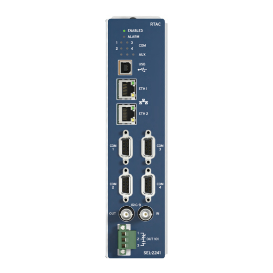
Front-Panel
The following figure shows the RTAC status LEDs that
aid system troubleshooting and the connectors for com-
munications and wiring.
Figure 1 SEL-2241 RTAC Front Panel, Copper Ethernet
Schweitzer Engineering Laboratories, Inc.
Mechanical Installation
Each SEL-2242 chassis/backplane has ten slots, labeled
A through J. Only Slot A supports the SEL-2241 RTAC
module.
To install the RTAC, tip the top of the module away from
the chassis, align the notch on the bottom of the module
with Slot A of the chassis, and place the module on the
bottom lip of the chassis as Figure 2 illustrates. The
module is aligned properly when it rests entirely on the
lip of the chassis.
Figure 2 Proper Module Placement
Next, carefully rotate the module into the chassis, mak-
ing sure that the alignment pin fits into the corresponding
slot at the top of the chassis (refer to Figure 3). Finally,
press the module firmly into the chassis and tighten the
chassis retaining screw.
SEL-2241 Data Sheet
Advertisement
Table of Contents

Related Manuals for Sel SEL-2241


Summary of Contents for Sel SEL-2241
- Page 1 ® Each SEL Axion system requires an RTAC module to serve as the system CPU. The SEL-2241 RTAC has all of the communications and custom logic capabilities of the standalone RTAC modules, but is mounted in and receives power from the Axion backplane.
-
Page 2: Communications Ports
Figure 3 Final Module Alignment Connections The SEL-2241 has four nonisolated serial ports. You can select all RTAC serial ports through software to be either Communications Ports EIA-232 or EIA-485/EIA-422. You can configure any serial protocol on the RTAC to use any of these serial NOTE: Never connect two RTACs via USB to one PC. -
Page 3: Led Indicators
When the contacts the module. bounce during the arc, they often weld closed. SEL has Step 5. Tip the top of the module away from the chassis designed, tested, and specified the outputs for this appli- and lift it from the bottom lip. - Page 4 SEL-2241 Disassembly Step 4. Install the new battery with the positive (+) side facing up. To disassemble the SEL-2241 RTAC, perform the fol- Step 5. Follow the SEL-2241 Reassembly instructions. lowing steps. Step 6. Set the device date and time.
-
Page 5: Specifications
Maximum Altitude: 2000 m Accuracy: 500 ns Time-Code Output (IRIG-B) Dimensions Refer to Section 2: Installation in the SEL-2240 Instruction Manual for On (1) State: > 2.4 V relay dimensions. Off (0) State: < 0.8 V Weight (Fully Populated Node) 50 ... - Page 6 Severity Level: 35 V/m Designation: voltage) IEC 61000-4-3:2008 Contact Protection: 270 Vac, 40 J Severity Level: 10 V/m IEC 60255-22-3:2007 Continuous Carry: 3 A @ 120 Vac Severity Level: 10 V/m 1.5 A @ 240 Vac SEL-2241 Data Sheet Schweitzer Engineering Laboratories, Inc.
- Page 7 Frequency: 0 Hz to 150 Hz Severity: Level 4, segment 4: 30 Vrms open-circuit, 15–150 kHz Emissions Radiated and Conducted IEC 60255-25:2000 Emissions: FCC 15-107:2014 FCC 15-109:2014 Severity Level: Class A Canada ICES-001 (A) / NMB-001 (A) Schweitzer Engineering Laboratories, Inc. SEL-2241 Data Sheet...
- Page 8 2350 NE Hopkins Court • Pullman, WA 99163-5603 U.S.A. trademark of their respective holders. No SEL trademarks may be used without written Tel: +1.509.332.1890 • Fax: +1.509.332.7990 permission. SEL products appearing in this document may be covered by U.S. and Foreign selinc.com • info@selinc.com patents.
Need help?
Do you have a question about the SEL-2241 and is the answer not in the manual?
Questions and answers