Beckhoff EL2904 Operating Instructions Manual
Twinsafe terminal with 4 digital fail-safe outputs
Hide thumbs
Also See for EL2904:
- Operating instructions manual (38 pages) ,
- Operating instructions manual (54 pages) ,
- Operating instructions manual (58 pages)

Related Manuals for Beckhoff EL2904


Summary of Contents for Beckhoff EL2904
- Page 1 Operating instructions | EN EL2904 TwinSAFE Terminal with 4 digital fail-safe outputs 2021-03-17 | Version: 2.3.0...
-
Page 3: Table Of Contents
The I/O construction kit is extended safely .............. 13 2.2.2 Safety concept ......................... 13 2.2.3 EL1904, EL2904 - Bus Terminals with 4 fail-safe inputs or outputs ........ 14 2.2.4 EL6900 - TwinSAFE logic terminal .................. 14 2.2.5 The fail-safe principle (Fail Stop) .................. 14 3 Product description.......................... 15... - Page 4 Table of contents 4.4.3 Inserting an EL2904...................... 35 4.4.4 Address settings on TwinSAFE terminals with 1023 possible addresses ....... 37 4.4.5 Entering a TwinSAFE address and parameters in the System Manager ...... 38 Diagnostics ............................ 40 4.5.1 Diagnostic LEDs ...................... 40 4.5.2...
-
Page 5: Foreword
Product features Only the product features specified in the current user documentation are valid. Further information given on the product pages of the Beckhoff homepage, in emails or in other publications is not authoritative. Disclaimer The documentation has been prepared with care. The products described are subject to cyclical revision. For that reason the documentation is not in every case checked for consistency with performance data, standards or other characteristics. -
Page 6: Safety Instructions
Offenders will be held liable for the payment of damages. All rights reserved in the event of the grant of a patent, utility model or design. Delivery conditions In addition, the general delivery conditions of the company Beckhoff Automation GmbH & Co. KG apply. Safety instructions 1.2.1... -
Page 7: Description Of Instructions
Failure to follow this safety instruction can lead to injuries to persons. NOTE Damage to the environment/equipment or data loss Failure to follow this instruction can lead to environmental damage, equipment damage or data loss. Tip or pointer This symbol indicates information that contributes to better understanding. EL2904 Version: 2.3.0... -
Page 8: Documentation Issue Status
Foreword Documentation issue status Version: 2.3.0 EL2904... - Page 9 • Document origin added 1.4.0 • Note regarding cable length and signal routing extended • Table listing causes for diagnostic messages amended 1.3.0 • Block diagram for EL2904 added 1.2.1 • Reference to EN 60068-2-29 removed 1.2.0 • ATEX notes amended •...
-
Page 10: System Description
System description The Beckhoff Bus Terminal system The Beckhoff Bus Terminal system is used for decentralized connection of sensors and actuators to a control system. The Beckhoff Bus Terminal system components are mainly used in industrial automation and building management applications. In its minimum configuration, a bus station consists of a Bus Coupler or a Bus Terminal Controller and Bus Terminals connected to it. -
Page 11: Bus Coupler
Fig. 2: Bus Coupler (EtherCAT) Connection technology Bus Coupler Wiring spring-loaded system Connection cross-section 0.08 mm² ... 2.5 mm², stranded wire, solid wire Fieldbus connection depending on fieldbus Power contacts 3 spring contacts Current load 10 A Rated voltage 24 V EL2904 Version: 2.3.0... -
Page 12: Bus Terminals
The power feed terminals play no part in the control of the terminals, and can be inserted at any locations within the terminal strip. Version: 2.3.0 EL2904... -
Page 13: Twinsafe
2.2.1 The I/O construction kit is extended safely With the TwinSAFE Terminals, Beckhoff offers the option of simply expanding the proven Bus Terminal system, and to transfer the complete cabling for the safety circuit into the already existing fieldbus cable. -
Page 14: El1904, El2904 - Bus Terminals With 4 Fail-Safe Inputs Or Outputs
EL1904, EL2904 - Bus Terminals with 4 fail-safe inputs or outputs The EL1904 and EL2904 Bus Terminals enable connection of common safety sensors and actuators. They are operated with the EL6900 TwinSAFE logic terminal. The TwinSAFE logic terminal is the link unit between the TwinSAFE input and output terminals. -
Page 15: Product Description
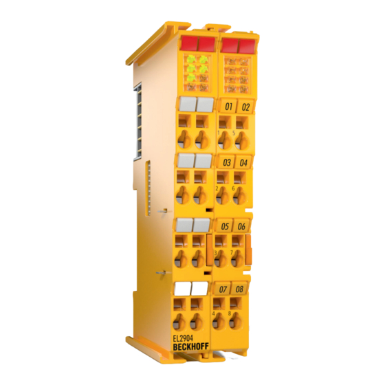
Product description EL2904 – TwinSAFE terminal with 4 digital fail-safe outputs The EL2904 is a safe output terminal with digital outputs for connecting actuators (contactors, relays, etc.) with a maximum current 0.5 A (24 V ). The Bus Terminal has 4 fail-safe outputs. -
Page 16: Intended Use
The buyer has to ensure the traceability of the device via the serial number. WARNING Commissioning test Before the EL1904/EL2904 can be used for the safety task, the user must carry out a commissioning test so that sensor and actuator wiring errors can be ruled out. CAUTION Use ferrules with plastic collars When using fine-wire cables for signal connections, use ferrules with plastic collars. - Page 17 EN 60529, so that the requirement for pollution degree 3 according to EN 60664-1 can be reduced to level 2. • The TwinSAFE components must be supplied by a SELV/PELV power supply unit with a maximum volt- age of U ≤ 36 V EL2904 Version: 2.3.0...
-
Page 18: Technical Data
Utilization category according to EN 60947-5-1 DC-13 Intended load Pilot Duty Actuators When selecting actuators please ensure that the EL2904 test pulses do not lead to actuator switching. Cable length between actuator and terminal unshielded max. 100 m shielded max. 100 m Wire cross-section min. -
Page 19: Safety Parameters
Element classification Type B 1. Special proof tests are not required during the entire service life of the EL2904 EtherCAT terminal. 2. Classification according to IEC 61508-2:2010 (chapter 7.4.4.1.2 and 7.4.4.1.3) The EL2904 EtherCAT Terminal can be used for safety-related applications within the meaning of IEC 61508:2010 up to SIL3 and EN ISO 13849-1:2015 up to PL e (Cat4). -
Page 20: Dimensions
Product description Dimensions Fig. 5: Dimensions of the EL2904 Width: 24 mm (side-by-side installation) Height: 100 mm Depth: 68 mm Version: 2.3.0 EL2904... -
Page 21: Block Diagram Of The El2904
Fig. 6: Block diagram of the EL2904 The block diagram shows the basic configuration of a channel in the EL2904. The part with a red border is present four times in the terminal. The high-side and low-side switches only exist once for all channels. This means that each channel has a total of four stop paths. -
Page 22: Operation
Please ensure that the digital TwinSAFE components are only transported and stored under the specified environmental conditions (see technical data). 4.2.3 Electrical installation 4.2.3.1 Connections within a Bus Terminal block The electric connections between the Bus Coupler and the Bus Terminals are automatically realized by joining the components: Version: 2.3.0 EL2904... -
Page 23: Fig. 7 Pe Power Contact
For insulation testing, disconnect the PE supply line at the Bus Coupler or the Potential Supply Terminal! In order to decouple further feed points for testing, these Power Feed Terminals can be released and pulled at least 10 mm from the group of terminals. EL2904 Version: 2.3.0... -
Page 24: Fig. 8 Connection Of A Cable To A Terminal Point
See the following table for the suitable wire size width. Wire size width (single core wires) 0.08 ... 2.5 mm Wire size width (fine-wire conductors) 0.08 ... 2.5 mm Wire size width (conductors with a wire end sleeve) 0.14 ... 1.5 mm Wire stripping length 8 ... 9 mm Version: 2.3.0 EL2904... -
Page 25: Fig. 9 El2904 Pin Assignment
5’ Output 2+ 6’ Output 2- 7’ Output 4+ 8’ Output 4- Test pulses When selecting actuators please ensure that the EL2904 test pulses do not lead to actuator switch- ing or diagnostic message from the EL2904. EL2904 Version: 2.3.0... -
Page 26: Fig. 10 Permitted Cable Length
When connecting a single actuator via its own continuous cabling (or via a sheathed cable), the maximum permitted cable length is 100 m. The use of contact points, connectors or additional actuators in the cabling reduces the maximum propagation. Cable routing Fig. 11: Cable routing Version: 2.3.0 EL2904... -
Page 27: Mechanical Installation
5 to 7 times per second. Test pulses for the outputs The following diagram shows a typical test pulse curve for the four outputs of an EL2904. The pa- rameters Current measurement active and Testing of outputs active are enabled. -
Page 28: Fig. 13 Installation Position And Minimum Distances
Fig. 13: Installation position and minimum distances In order to ensure optimum convection cooling, the distances to neighboring devices and to control cabinet walls must not be smaller than those shown in the diagram. Version: 2.3.0 EL2904... -
Page 29: Fig. 14 Example Configuration For Temperature Measurement
The key parameter is always the maximum permitted internally measured temperature of 95°C, above which the TwinSAFE terminals switch to safe state and report an error. The internal tempera- ture can be read from the TwinSAFE components via CoE (see chapter Diagnose). EL2904 Version: 2.3.0... -
Page 30: Fig. 15 Installation On The Mounting Rail
When installing the components, make sure that the locking mechanism doesn't come into conflict with the fixing bolts of the mounting rail. For fastening mounting rails with a height of 7.5 mm under the terminals and couplers, use flat fastening components such as countersunk head screws or blind rivets. Version: 2.3.0 EL2904... -
Page 31: Fig. 16 Removal Of Mounting Rails
2. Grasp the released terminal with thumb and index finger simultaneous at the upper and lower grooved housing surfaces and pull the terminal away from the mounting rail. EL2904 Version: 2.3.0... -
Page 32: Twinsafe Reaction Times
The typical response time is based on the following formula: ReactionTime Sensor Input Comm Logic Comm Output Actuator with ReactionTime Worst case response time The worst-case response time is the maximum time required for switching off the actuator in the event of an error. Version: 2.3.0 EL2904... -
Page 33: Tested El2904 Devices
4.2.6 Tested EL2904 devices The following list contains devices that were tested together with the EL2904 TwinSAFE terminal. The results only apply for the current device hardware version at the time of testing. The tests were carried out in a laboratory environment. Modifications of these products cannot be considered here. If you are unsure please test the hardware together with the TwinSAFE terminal. -
Page 34: Operation In Potentially Explosive Atmospheres (Atex)
80°C at the wire branching points, then cables must be selected whose temperature data correspond to the actual measured temperature values! Observe the permissible ambient temperature range of 0 to 55 °C when using Beckhoff fieldbus compo- nents in potentially explosive atmospheres! -
Page 35: Date Code And Serial Number
Inserting a Bus Terminal See TwinCAT automation software documentation. 4.4.3 Inserting an EL2904 An EL2904 is inserted in the same way as any other Beckhoff Bus Terminal. In the list open Safety Terminals (ELx9xx) and select the EL2904. EL2904 Version: 2.3.0... -
Page 36: Fig. 19 Inserting An El2904
Operation Fig. 19: Inserting an EL2904 Version: 2.3.0 EL2904... -
Page 37: Address Settings On Twinsafe Terminals With 1023 Possible Addresses
TwinSAFE terminal. TwinSAFE addresses between 1 and 1023 are available. DIP switch Address 1023 WARNING TwinSAFE address Each TwinSAFE address may only be used once within a network / a configuration! The address 0 is not a valid TwinSAFE address! EL2904 Version: 2.3.0... -
Page 38: Entering A Twinsafe Address And Parameters In The System Manager
The FSoE address set at the DIP switch must also be entered under the FSoE tab (FSoE_Address entry). Fig. 21: Entering the FSoE address The EL2904 parameters are set under the respective TwinSAFE connection in the Connection and Parameter tabs. Fig. 22: Setting the connection of the TwinSAFE connection Version: 2.3.0... -
Page 39: Fig. 23 Setting The Parameters Of The Twinsafe Connection
A calculation example for the performance level can be found in the TwinSAFE application manual. There are no known application for which it would make sense to set Testing of outputs active to FALSE, while Current measurement active is set to TRUE. EL2904 Version: 2.3.0... -
Page 40: Diagnostics
Diag 3 (red) and Diag 4 (red) If the Diag 3 LED is lit, the Diag 4 LED indicates internal terminal errors. These errors lead to shutdown of the terminal. The terminal must be checked by Beckhoff Automation GmbH & Co. KG. -
Page 41: Diagnostic Objects
Operation Flashing Code In the case of such an error, the Diag 4 LED on the EL2904 displays flashing codes that describe the error in more detail. A flashing code consists of four sequences, which are interrupted in each case by a short break. After the four sequences there is a long break, following which the flashing code is displayed again. - Page 42 (4...7) are set. This is independent of the parameter settings. Differing diagnostic messages possible Due to the variable order or execution of the test series, diagnostic messages differing from those given in the table above are possible. Version: 2.3.0 EL2904...
-
Page 43: Possible Causes Of Diagnostic Messages
Check the installation position of the terminal and modify it according to the specifications in section Mechanical instal- An internal measuring point shows an elevated tem- lation, if required perature due to inadequate convection. EMC faults Take suitable EMC measures Internal defect Replace terminal EL2904 Version: 2.3.0... -
Page 44: Maintenance
YY: Year of manufacture Year: 2011 SW: Software version Software version: 05 HW: Hardware version Hardware version: 00 In addition the TwinSAFE terminals bear a unique serial number. 00000000 17110500 Fig. 25: Unique serial number of a TwinSAFE terminal Version: 2.3.0 EL2904... -
Page 45: Decommissioning
Disposal In order to dispose of the device, it must be removed. In accordance with the WEEE Directive 2012/19/EU, Beckhoff takes back old devices and accessories in Germany for proper disposal. Transport costs will be borne by the sender. Return the old devices with the note "for disposal" to: Beckhoff Automation GmbH &... -
Page 46: Appendix
Please contact your Beckhoff branch office or representative for local support and service on Beckhoff products! The addresses of Beckhoff's branch offices and representatives round the world can be found on her internet pages: https://www.beckhoff.com You will also find further documentation for Beckhoff components there. -
Page 47: Certificates
Appendix Certificates EL2904 Version: 2.3.0... - Page 48 Appendix Version: 2.3.0 EL2904...
- Page 49 Slot and key system and screwless (spring-loaded) connection system........Fig. 2 Bus Coupler (EtherCAT)......................Fig. 3 TwinSAFE Terminals (EtherCAT)....................Fig. 4 EL2904 – TwinSAFE terminal with 4 digital fail-safe outputs ............Fig. 5 Dimensions of the EL2904......................Fig. 6 Block diagram of the EL2904....................... Fig. 7 PE power contact.........................
- Page 51 More Information: www.beckhoff.com/el2904 Beckhoff Automation GmbH & Co. KG Hülshorstweg 20 33415 Verl Germany Phone: +49 5246 9630 info@beckhoff.com www.beckhoff.com...
Need help?
Do you have a question about the EL2904 and is the answer not in the manual?
Questions and answers