
Related Manuals for Beckhoff EL6900


Summary of Contents for Beckhoff EL6900
- Page 1 Operating Instructions for EL6900 TwinSAFE Logic Terminal Version: 2.2.0 Date: 2017-05-10...
-
Page 3: Table Of Contents
2.2.4 EL6900 - TwinSAFE logic terminal .................. 13 2.2.5 The fail-safe principle (Fail Stop) .................. 13 3 Product description.......................... 14 EL6900 - TwinSAFE logic terminal .................... 14 Intended use .......................... 14 Technical data .......................... 16 Safety parameters ........................ 17 Dimensions ........................... 18 4 Operation.............................. 19 Environmental conditions...................... - Page 4 Append a function block.................... 36 4.4.10 EL6900 user and version administration................ 41 4.4.11 Export and import of a TwinSAFE project ................ 46 4.4.12 EL6900 info data ...................... 47 4.4.13 Loading the project into the EL6900 ................ 47 4.4.14 Communication between TwinCAT controllers .............. 49 Diagnostics ........................... 53 4.5.1 Diagnostic LEDs....................... 53...
-
Page 5: Foreword
Product features Only the product features specified in the current user documentation are valid. Further information given on the product pages of the Beckhoff homepage, in emails or in other publications is not authoritative. Disclaimer The documentation has been prepared with care. The products described are subject to cyclical revision. For that reason the documentation is not in every case checked for consistency with performance data, standards or other characteristics. -
Page 6: Safety Instructions
Offenders will be held liable for the payment of damages. All rights reserved in the event of the grant of a patent, utility model or design. Delivery conditions In addition, the general delivery conditions of the company Beckhoff Automation GmbH & Co. KG apply. Safety instructions 1.2.1... -
Page 7: Description Of Safety Symbols
Damage to the environment or devices Failure to follow the instructions associated with this symbol can lead to damage to the en- vironment or equipment. Attention Tip or pointer This symbol indicates information that contributes to better understanding. Note EL6900 Version: 2.2.0... -
Page 8: Documentation Issue Status
• Installation position and minimum distances extended • Notes regarding overvoltage protection amended • Diagnostics for CoE object 0xFA00 described 1.1.0 • Minor amendments for EtherCAT • Copyright and disclaimer modified • Support and service addresses updated 1.0.0 • First released version Version: 2.2.0 EL6900... -
Page 9: System Description
System description The Beckhoff Bus Terminal system The Beckhoff Bus Terminal system is used for decentralized connection of sensors and actuators to a control system. The Beckhoff Bus Terminal system components are mainly used in industrial automation and building management applications. In its minimum configuration, a bus station consists of a Bus Coupler or a Bus Terminal Controller and Bus Terminals connected to it. -
Page 10: Bus Coupler
Fig. 2: Bus Coupler (EtherCAT) Connection technology Bus Coupler Wiring spring-loaded system Connection cross-section 0.08 mm² ... 2.5 mm², stranded wire, solid wire Fieldbus connection depending on fieldbus Power contacts 3 spring contacts Current load 10 A Rated voltage 24 V Version: 2.2.0 EL6900... -
Page 11: Bus Terminals
The power feed terminals play no part in the control of the terminals, and can be inserted at any locations within the terminal strip. EL6900 Version: 2.2.0... -
Page 12: Twinsafe
The new ELx9xx series Bus Terminals only include three basic functionalities: digital inputs EL19xx, digital outputs EL29xx and a logic unit EL6900. For a large number of applications, all sensors and actuators can be wired on these Bus Terminals. The required logical link of the inputs and the outputs is handled by the EL6900. -
Page 13: El1904, El2904 - Bus Terminals With 4 Fail-Safe Inputs Or Outputs
The EL1904 and EL2904 Bus Terminals enable connection of common safety sensors and actuators. They are operated with the EL6900 TwinSAFE logic terminal. The TwinSAFE logic terminal is the link unit between the TwinSAFE input and output terminals. It enables the configuration of a simple, flexible and cost-effective decentralized safety control system. -
Page 14: Product Description
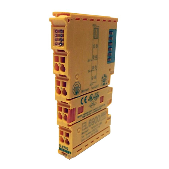
EL6900 - TwinSAFE logic terminal The TwinSAFE logic terminal is the link unit between the TwinSAFE input and output terminals. The EL6900 meets the requirements of IEC 61508:2010 SIL 3, DIN EN ISO 13849-1:2006 (Cat 4, PL e), NRTL, UL508, UL1998 and UL991. - Page 15 • The EL1904 is an EtherCAT Terminal with 4 digital fail-safe inputs. • The EL2904 is an EtherCAT Terminal with 4 digital fail-safe outputs. • The EL6900 is an EtherCAT Terminal with integrated TwinSAFE logic. These TwinSAFE components are suitable for operation on the •...
-
Page 16: Technical Data
Dynamic according to the TwinSAFE configuration in the TwinCAT System Manager Output process image Dynamic according to the TwinSAFE configuration in the TwinCAT System Manager EL6900 supply voltage (PELV) 24 V (–15%/+20%) Current consumption via E-bus approx. 188 mA Power dissipation of the terminal... -
Page 17: Safety Parameters
Element classification Type B 1. Special proof tests are not required during the entire service life of the EL6900 EtherCAT terminal. 2. Classification according to IEC 61508-2:2010 (see chapters 7.4.4.1.2 and 7.4.4.1.3) The EL6900 EtherCAT Terminal can be used for safety-related applications within the meaning of IEC 61508:2010 up to SIL3 and EN ISO 13849-1 up to PL e (Cat4). -
Page 18: Dimensions
Product description Dimensions Fig. 5: Dimensions of the EL6900 Width: 12 mm (side-by-side installation) Height: 100 mm Depth: 68 mm Version: 2.2.0 EL6900... -
Page 19: Operation
Bring the bus system into a safe, de-energized state before starting installation, disassem- bly or wiring of the devices! DANGER 4.2.3.1 Control cabinet / terminal box The TwinSAFE terminals must be installed in a control cabinet or terminal box with IP54 protection class according to IEC 60529 as a minimum. EL6900 Version: 2.2.0... -
Page 20: Fig. 6 Installation Position And Minimum Distances
Fig. 6: Installation position and minimum distances In order to ensure optimum convection cooling, the distances to neighboring devices and to control cabinet walls must not be smaller than those shown in the diagram. Version: 2.2.0 EL6900... -
Page 21: Fig. 7 Example Configuration For Temperature Measurement
The example configuration for the temperature measurement consists of an EK1100 EtherCAT coupler with connected terminals that match the typical distribution of digital and analog signal types at a machine. On the EL6900 a safety project is active, which reads safe inputs and enables all 4 safe outputs during the measurement. -
Page 22: Fig. 8 Installation On The Mounting Rail
For fastening mounting rails with a height of 7.5 mm under the terminals and couplers, use flat fastening compo- nents such as countersunk head screws or blind rivets. Version: 2.2.0 EL6900... -
Page 23: Electrical Installation
(e.g. analog Bus Terminals or digital 4- Note channel Bus Terminals) do not or not fully loop through the power contacts. Power Feed Terminals (EL91xx, EL92xx) interrupt the power contacts and thus represent the start of a new supply rail. EL6900 Version: 2.2.0... -
Page 24: Fig. 10 Pe Power Contact
The PE power contact must not be used for other potentials! DANGER 4.2.4.2 Overvoltage protection If protection against overvoltage is necessary in your plant, provide a surge filter for the voltage supply to the Bus Terminal blocks and the TwinSAFE terminals. Version: 2.2.0 EL6900... -
Page 25: Fig. 11 Connection Of A Cable To A Terminal Point
2. The wire can now be inserted into the round terminal opening without any force. 3. The terminal closes automatically when the pressure is released, holding the wire safely and perma- nently. Wire cross section 0,08 ... 2.5 mm Strip length 8 ... 9 mm EL6900 Version: 2.2.0... -
Page 26: Fig. 12 El6900/El6910 Pin Assignment
Operation 4.2.4.4 EL6900/EL6910 pin assignment Fig. 12: EL6900/EL6910 pin assignment Terminal point Output Signal not used, no function not used, no function not used, no function not used, no function not used, no function not used, no function not used, no function not used, no function Version: 2.2.0... -
Page 27: Twinsafe Reaction Times
Reaction time of the logic terminal. This is the cycle time of the logic terminal and typically ranges from 500 µs to 10 ms for the EL6900, depending on the size of the safety project. The actual cycle time can be read from the terminal. -
Page 28: Tested El1904 Devices
The tests were carried out in a laboratory environment. Modifications of these products cannot be considered here. If you are unsure please test the hardware together with the TwinSAFE terminal. Version: 2.2.0 EL6900... -
Page 29: Operation In Potentially Explosive Atmospheres (Atex)
80°C at the wire branching points, then cables must be selected whose temperature data correspond to the actual measured temperature values! Observe the permissible ambient temperature range of 0 to 55 °C when using Beckhoff fieldbus components in potentially explosive atmospheres! -
Page 30: Identification
Operation 4.3.2 Identification Beckhoff fieldbus components that are certified for use in potentially explosive atmospheres bear one of the following markings: II 3 G Ex nA II T4 KEMA 10ATEX0075 X Ta: 0 - 55°C II 3 G Ex nA nC IIC T4 KEMA 10ATEX0075 X Ta: 0 - 55°C... -
Page 31: Inserting A Bus Coupler
See TwinCAT automation software documentation. 4.4.4 Inserting an EL6900 An EL6900 is inserted in the same way as any other Beckhoff Bus Terminal. In the list open Safety Terminals (ELx9xx) and select the EL6900. Fig. 15: Inserting an EL6900 Size of the process image The process image of the EL6900 is adjusted dynamically based on the TwinSAFE configu- ration created in the TwinCAT automation software. -
Page 32: Address Settings On Twinsafe Terminals With 1023 Possible Addresses
The address 0 is not a valid TwinSAFE address! WARNING 4.4.6 Registering the TwinSAFE addresses in the TwinCAT automation software The TwinSAFE address set at the DIP switch must also be entered under the TwinSAFE Logic tab (TwinSAFE address entry). Version: 2.2.0 EL6900... -
Page 33: Creating A Twinsafe Group
A TwinSAFE group is a group of TwinSAFE terminals (inputs and outputs) that are logically linked via an EL6900. Any communication faults in the TwinSAFE connections of this group lead to the whole group being switched off. Other TwinSAFE groups are not affected. -
Page 34: Fig. 18 Creating A Twinsafe Group
Operation Fig. 18: Creating a TwinSAFE group Version: 2.2.0 EL6900... -
Page 35: Twinsafe Group Signals
At least one TwinSAFE connection of TwinSAFE group has an error FB-In FALSE All TwinSAFE connections of the TwinSAFE group have no errors Standard-Out OUT ERR TwinSAFE-Out FALSE Always FALSE, since the EL6900 has no local outputs FB-In Standard-Out EL6900 Version: 2.2.0... -
Page 36: Append A Function Block
4.4.9 Append a function block The EL6900 TwinSAFE logic terminal features function blocks like Emergency Stop, Machine Monitoring, AND, OR, Decoupler, Operation Mode, etc. A function block is added by right-clicking on the associated TwinSAFE function block list in the tree structure and selecting Append Function Block in the dialog box with the left mouse button (see diagram). -
Page 37: Fig. 22 Appended Emergency Stop Block
Operation Fig. 22: Appended Emergency Stop block EL6900 Version: 2.2.0... -
Page 38: Fig. 23 Function Block Input Settings
Discrepancy Time can be set for monitoring the two inputs for simultaneous switching. Make Contact: Contact type setting Break Contact: Contact type setting The inputs are now activated. Fig. 24: Activated inputs The inputs can now be linked. Version: 2.2.0 EL6900... -
Page 39: Fig. 25 Link Inputs
Operation Fig. 25: Link inputs Select the variable type: Fig. 26: Select the variable type Clicking on the New button opens the following dialog: EL6900 Version: 2.2.0... -
Page 40: Fig. 27 Available Channels
The desired channel is selected and marked with the mouse. The selection is confirmed via the OK button. Fig. 28: Selection of the desired channel The name of the variables should now be entered in the Link Alias field. Version: 2.2.0 EL6900... -
Page 41: El6900 User And Version Administration
EL6900 user and version administration The EL6900 has a user administration function. The user Administrator can't be deleted, but its default password can and should be changed into a customer specific one. This is to be done via the button Change Password. -
Page 42: Fig. 31 El6900 User Administration
Operation Fig. 31: EL6900 user administration Via the button Upload the list of created users is read from the EL6900. Fig. 32: User Administration - Upload To create or delete users, the administrator password is needed. By a left mouse click onto Add User… the dialog Login will be opened. -
Page 43: Fig. 33 User Administration - Login
6 characters long at minimum. The new user has the same rights like the administrator except the right to create or delete users. Via the button OK the data is assumed and displayed within the User Administration. EL6900 Version: 2.2.0... -
Page 44: Fig. 35 User Administration - User List
OK. The button Cancel finishes the procedure without changes. To change the password of a user, the designed user has to be selected and via the button Change Password… the dialog Change Password will open. Version: 2.2.0 EL6900... -
Page 45: Fig. 37 User Administration - Login To Change Password
Enter the new password twice. The new password has to be 6 characters long at minimum. Via the button OK the dialog will be left. Clicking on the button Version History will bring up the version history for the EL6900 (which cannot be deleted) that indicates who activated what version of a project on the EL6900, and when. -
Page 46: Export And Import Of A Twinsafe Project
XML file into another TwinCAT installation using the Import button. During the import TwinCAT attempts to restore the connections within the logic to the safe input and output terminals via the FSoE address. An error message is displayed if this is not possible. Version: 2.2.0 EL6900... -
Page 47: El6900 Info Data
Info data can be displayed in the cyclic process image via the checkboxes Map Project CRC and Map Serial Number. These info data show the current safety project CRC and the serial number of the EL6900 and can be used in a visualization, for example. -
Page 48: Fig. 42 Loading The Project Into The El6900
EL6900 project design limits TwinSAFE connections max. 128 (with 1 or 2 bytes safe user data per connection) max. 50 connections per TwinSAFE group Only 16 connections of an EL6900 can be slave connections. Supported hardware for EL6900 EL1904 (all) TwinSAFE connections... -
Page 49: Communication Between Twincat Controllers
Operation TwinSAFE connection Only one TwinSAFE connection between two TwinSAFE terminals is possible. Between two EL6900 logic terminals a connection can be set up that may contain up to 14 bytes Note safe user data. 4.4.14 Communication between TwinCAT controllers The MASTER_MESSAGE and SLAVE_MESSAGE data types are used for communication between two or more TwinCAT controllers via network variables. - Page 50 Fig. 45: Creation of a variable for the master message Fig. 46: Creation of a variable for the slave message These newly-created variables are now linked with the network variables already created. This is carried out for both the master and the slave message. Version: 2.2.0 EL6900...
- Page 51 Fig. 48: Settings for the TwinSAFE connection If several connections are to be established, a unique ID must be set for each Publisher variable. EL6900 Version: 2.2.0...
- Page 52 This ID must also be set on the partner device, i.e. the Subscriber. The network variables can now be used in the project. The inputs are shown TwinSAFE Input, the outputs under TwinSAFE Output. Fig. 50: Attach TwinSAFE variable for inputs Version: 2.2.0 EL6900...
-
Page 53: Diagnostics
Fig. 51: Attach TwinSAFE variable for outputs Diagnostics 4.5.1 Diagnostic LEDs The LEDs Diag 1 to Diag 4 display diagnostic information for the EL6900. Fig. 52: EL6900 diagnostic LEDs 4.5.1.1 Diag 1 LED (green) The Diag 1 LED is currently always on when a project is loaded into the terminal. -
Page 54: Diagnostic Object
(e.g. using TwinCAT) of the CoE objects will permanently set the TwinSAFE com- CAUTION ponents to the Fail-Stop state. Index FA80 : Internal temperature values The CoE objects FA80 indicate the current internal temperature values of the EL6900. Index Name Meaning Flags Default... - Page 55 Due to the variable order or execution of the test series, diagnostic messages differing from those given in the table above are possible. Note Index F100 : Device Status This CoE object is also mapped to the EL6900 process image under DEVICE Inputs. Index Name Meaning Data type Flags...
-
Page 56: Cycle Time Of The Safety Project
0001hex. This value should be reset to 0 once the cycle time has been determined. 4.5.4 Status LEDs The LEDs State 1 to State 4 indicate the current status of the EL6900. Fig. 53: EL6900 status LEDs State 1 State 2 State 3... -
Page 57: Service Life
• Housing components (polycarbonate, polyamide (PA6.6)) are suitable for plastic recycling. • Metal parts can be sent for metal recycling. • Electronic parts such as disk drives and circuit boards must be disposed of in accordance with national electronics scrap regulations. EL6900 Version: 2.2.0... -
Page 58: Appendix
Beckhoff's branch offices and representatives Please contact your Beckhoff branch office or representative for local support and service on Beckhoff products! The addresses of Beckhoff's branch offices and representatives round the world can be found on her internet pages: http://www.beckhoff.com You will also find further documentation for Beckhoff components there. -
Page 59: Certificates
Appendix Certificates EL6900 Version: 2.2.0... - Page 60 Appendix Version: 2.2.0 EL6900...
- Page 61 Fig. 41 EL6900 info data.......................... Fig. 42 Loading the project into the EL6900 .................... Fig. 43 Link with the TwinSAFE logic terminal EL6900 ................Fig. 44 Make known the connection created to the TwinSAFE logic terminal ......... EL6900 Version: 2.2.0...
- Page 62 Setting a unique ID ........................Fig. 50 Attach TwinSAFE variable for inputs ................... Fig. 51 Attach TwinSAFE variable for outputs ..................Fig. 52 EL6900 diagnostic LEDs ......................Fig. 53 EL6900 status LEDs ........................Fig. 54 Unique serial number of a TwinSAFE terminal................Version: 2.2.0...
Need help?
Do you have a question about the EL6900 and is the answer not in the manual?
Questions and answers