Advertisement
Quick Links
—
ABB EXCITATION SYSTEMS
®
UNITROL
1010 and UNITROL
Quick installation guide
Safety instructions
Read the safety instructions in the User Manual .
WARNING!
•
Obey the safety instructions to prevent physical injury or death, or
damage to the equipment.
•
Read and make sure that you understand the operating and safety
instructions before you operate the unit.
•
If you are not a qualified electrician, do not do electrical installation or
maintenance work.
•
Use personal protective equipment, such as, safety shoes and gloves.
Obey these safety precautions before you do work on the system:
1.
Clearly identify the work location and equipment.
2.
Disconnect all possible voltage sources. Make sure that reconnection is not
possible. Lock out and tag out.
•
Open the main disconnecting device of the AVR.
•
Disconnect any external power sources from the control circuits before
you do work on the control cables.
•
If you have a permanent magnet generator connected to the AVR,
disconnect it from the AVR with a safety switch or by other means.
•
After you disconnect the AVR, always wait for 5 minutes to let the
intermediate circuit capacitors discharge before you continue.
•
Do not do work on the AVR when the amber warning LED flashes.
3.
Protect any other energized parts in the work location against contact.
4.
Take special precautions when you are near bare conductors.
5.
Measure that the installation is de-energized.
•
Use a multimeter with an impedance of at least 1 Mohm.
•
Make sure that the voltage between the AVR input power terminals
(PWR L1, PWR L2 and PWR L3) and the grounding terminal (PE) is near
0 V.
•
Make sure that the voltage between the AVR output terminals (IE+, IE-
and ExCap) and the grounding terminal (PE) is close to 0 V.
6.
Install temporary grounding as required by the local regulations.
7.
Ask for a permit to work from the person in control of the electrical
installation work.
Residual danger areas
WARNING! Do not do work on the AVR when the amber warning LED
flashes.
When the AVR operates,
•
The voltage in the power section can be up to 300 V AC and the short-circuit
current is very high.
•
The voltage in the control cabinet is more than 50 V.
When the AVR is disconnected from power supplies, the large capacitors in the
AVR hold a charge for some time. Wait for at least 5 minutes for the capacitors
to discharge before you do work on the AVR. An amber warning LED flashes if
the internal voltage is more than 30 V DC.
Warning labels are attached to all of the cubicle doors to warn personnel against
opening the doors during operation.
If the device is built into a larger system, additional warning labels are attached
to the inside of the cubicle doors and to the covers of the power converter
modules.
Consider the residual danger areas when you do work on the excitation system:
•
Danger from live equipment inside the excitation system, if the protective
covers are removed.
•
Hazardous voltages from the rotor field winding and the secondary side of
the excitation transformer.
•
Danger from charged capacitors if a cabinet door is open immediately after
the system stops.
•
Danger from main and auxiliary voltages when cubicle doors are open.
Introduction
This document is a quick installation guide for the UNITROL 1010 and
UNITROL 1020 automatic voltage regulator. Make sure that you read and
understand this document before you install or use the product. This document
is meant only as a brief guide to the product. For detailed information on the
product, refer to the User Manual .
Device description
UNITROL 1010 and UNITROL 1020 are automatic voltage regulators (AVR) for
synchronous machines of up to 80 MVA. The AVRs can be used for the excitation
of indirectly excited synchronous machines and motors. The AVRs can also
operate as a reactive power regulators, power factor regulators or field current
regulators.
Product package
Contents of the product package:
•
UNITROL 1000 series AVR
•
Special red USB cable that is used to power and to connect with the AVR.
Keep this USB cable in a safe place.
®
1020
•
Red jumper blocks (3 pcs.)
•
Quick installation guide and test certificate
Make sure that all of the listed items are in the product package and that there is
no damage to the items.
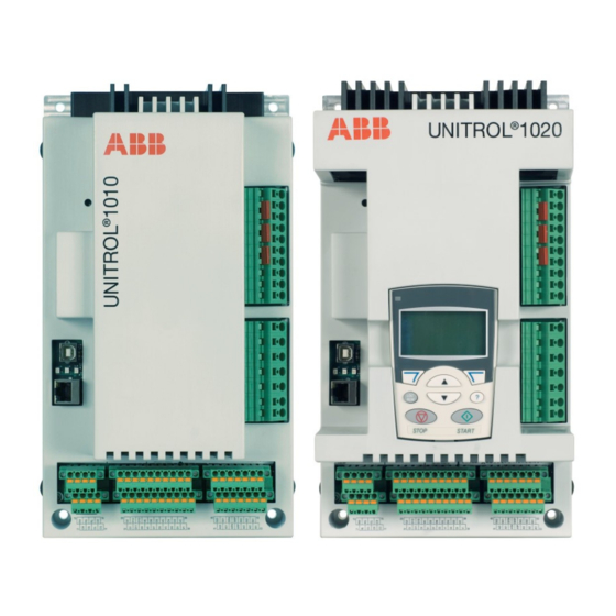
Hardware overview
Primary parts of the AVR. Refer to the User Manual for more information.
2
4
6
7
8
9
10
2
No. Description
1
Heat sink
2
Mounting holes
3
Unit type designation
4
Warning LED
5
Front cover
6
USB port
7
Status LEDs
8
Ethernet port
Warning and status indicators
Color
Description
Amber
Warning LED
Flashes: Do not do work on the AVR! The internal voltage is more than 30 V DC.
Green
Operating status
ON: Device controllers are active
Flashes: Device software is active
Yellow
Excitation status
ON: Excitation is active
Flashes: A limiter is active
Red
Alarm status
ON: An alarm or a trip is active
Flashes:
• Startup failure
• Parameter download failure
• Excitation output is blocked
Mechanical installation
For detailed information on mechanical installation, refer to the User Manual .
Install the AVR in an indoor area that is dry and dust-free, and that does not
contain volatile gases, acid fumes or similar hazards.
Examine the installation area and refer to technical data to make sure that:
•
The maximum ambient temperature is in the permitted range.
•
The vibration is limited and within the permitted class.
•
The ingress protection and pollution degree are suitable.
•
The EMC environment is suitable.
Installation requirements:
•
Install the AVR vertically to make sure that cooling operates correctly.
•
Free space requirements:
•
50 mm above the AVR
•
20 mm below the AVR
•
10 mm on the left and right sides of the AVR
•
Make sure that there is sufficient cooling air flow around the AVR.
•
Make sure that other devices do not blow hot air on to the AVR.
•
The AVR is designed to be installed with suitable hardware to an installation
plate.
•
Make sure that the frame of the AVR is electrically grounded (PE) to the
installation plate with a grounding wire (≥4 mm
Use toothed washers to get a good electrical ground contact.
Installation procedure:
1.
Refer to Dimensions for the mounting hole dimensions.
2.
Make the appropriate holes in the installation plate.
3.
Attach the AVR to the installation plate with suitable hardware, for example,
M6 screws to a torque of 10 Nm. The mounting holes have a diameter of
6.5 mm.
4.
Make sure that there is a good electrical ground connection between the
installation plate and the AVR. The installation plate must be electrically
grounded (PE).
Electrical installation
For detailed information on electrical installation, refer to the User Manual .
SM
E
1
2
3
5
13
15
REM
100.0%
S
AUTO NoLoad
0.00
% UM
0.00
A Ie
SETPNT
12:45
MENU
14
?
11
12
2
No. Description
9
RS-485 (X1300) terminal
10
CAN (X1302) terminal
11
Digital I/Os
12
Analog I/Os
13
Power terminals
• Protective earth (PE)
• Input power U
PWR
• Auxiliary power U
AUX
• Excitation output
14
Measurement terminals
, U
, I
U
M
NET
M
15
Control panel (UNITROL 1020 only)
2
) through a mounting hole.
1
2
11
3
8
12
4
10
13
5
14
9
15
6
7
16
7
No. Description
No. Description
1
Digital I/Os
9
Power electronics control (PWM)
Max. cable length 30 m
2
Analog I/Os
10
Communication MCU
Max. cable length 30 m
3
Network voltage measurement U
11
Control Power Supply input AUX L1–L3
NET
4
Machine voltage measurement U
12
Ethernet connection
M
Max. cable length 100 m
5
Machine current measurement I
13
USB connection
M2
Max. cable length 3 m
6
External capacitor ExCap (-)
14
RS-485 connection
Max. cable length 500 m
7
Excitation output I
& U
15
CAN connection
e
e
Max. cable length 3 m
8
Measurement and control unit (DSP)
16
Excitation Power Supply input
PWR L1–L3
CAUTION! Separate control (I/O) cables from the excitation (power and
measurement) cables to avoid electromagnetic interference.
Cable dimension requirements:
Connection type
Cross-section area requirement
Excitation cables
2
0.2 to 4 mm
Terminals 1 to 17
Control cables (I/O)
2
0.2 to 2.5 mm
Terminals 20 to 77
Grounding
Connect the AVR to the protective earth at terminal 17 with a 4 mm
wire.
Make an additional grounding connection through the mounting holes to the
installation plate (if it is connected to the protective earth) or with a 4 mm
cable to the protective earth.
Make sure that the grounding connections are as short as possible.
Additional signal ground terminals are provided for the control cables.
Inrush current limitation
The large internal DC capacitor of the AVR can cause a high inrush current
especially with a strong voltage source.
WARNING! To prevent damage to the AVR, make sure that the inrush
current is not more than 200 A for 10 ms.
To prevent damage to the AVR from a high inrush current:
Method
Description
Shunt supply
The excitation power is taken from the generator output over a shunt
transformer. Use an excitation supply transformer with a maximum
power of 10 kVA.
PMG supply
The excitation power is taken from a permanent magnet generator
(PMG). The maximum permitted output power of the PMG is 10 kVA.
Auxiliary windings
The excitation power is taken from an additional stator winding of
the generator.
Auxiliary supply
The excitation power is taken from an auxiliary power source. Use an
excitation supply transformer with a maximum power of 10 kVA.
DC battery
The excitation power is taken from a battery. Limit the inrush current
with a resistor.
To calculate the inrush current, you can use a capacitor voltage of 0 V at startup.
The external resistor for a 200 V AC input is typically 1.5 Ω.
Power and measurement terminals
Terminals
Type
Ref.
Label
Power
17
PE
terminals
1
16
PWR L1
1
15
AUX L1 (+)
1
14
PWR L2
1
13
AUX L2 (-)
1
12
PWR L3
1
11
AUX L3
10
IE+
9
IE-
8
ExCap (-)
Measurement
7
ML1
terminals
6
ML2
5
ML3
4
NW1
3
NW3
2
MC2+
1
MC2-
1) To reduce wiring, you can connect each phase of the excitation power inputs
(PWR) and auxiliary power supply inputs (AUX) with the included jumpers.
Commissioning
For detailed instructions on commissioning, refer to the User Manual .
Commissioning procedure overview:
1.
Make sure that all of the connections are correct and safe.
2.
Download the configuration file to the AVR. Make sure that the parameters
are correct.
3.
Examine the digital and analog I/Os in standstill.
4.
Do tests with the machine:
a) Standstill
•
Measure resistance of exciter stator winding.
b) No load condition
•
Increase the speed of the machine to nominal.
•
Start excitation in Manual mode and increase the manual setpoint until
machine voltage is 50%.
•
Use CMT 1000 to verify the AVR measurements and compare them with
other equipment used, such as protection devices.
•
Increase the setpoint until the machine voltage is 100% and tune the
AVR with the AVR tuning assistant.
•
Do step response tests to examine performance in Manual mode and
Auto mode.
c) Machine connected to grid
•
Select AUTO (voltage regulator).
•
Increase the AUTO setpoint to verify the polarity of the of I
measurement. Q must increase.
d) Do step response tests to examine performance in Auto mode and direct
VAR regulator modes.
5.
Finalizing commissioning
a) Save the parameters on the AVR and verify the status with CMT 1000.
b) Save backup files for project documentation.
WARNING! To prevent unstable regulation and damage to the machine,
do tests for all used regulator modes and limiters.
WARNING! If you use synchronization, refer to the procedure in the user
manual. Take special care with synchronization to prevent physical
injury or death, or damage to the equipment.
AWG 24 to AWG 10
AWG 24 to AWG 12
2
grounding
2
Signal description
Protective earth
Input power L1
Auxiliary supply L1
Input power L2
Auxiliary supply L2
Input power L3
Auxiliary supply L3
Exciter current +
Exciter current -
External capacitor -
Machine voltage L1
Machine voltage L2
Machine voltage L3
Network voltage L1
Network voltage L3
Machine current +
Machine current -
M
Advertisement

Related Manuals for ABB UNITROL 1010


Summary of Contents for ABB UNITROL 1010
- Page 1 Finalizing commissioning a) Save the parameters on the AVR and verify the status with CMT 1000. This document is a quick installation guide for the UNITROL 1010 and UNITROL 1020 automatic voltage regulator. Make sure that you read and b) Save backup files for project documentation.
- Page 2 0.5 to 99% 143.5 147.5 11.9 11.0 If you do not have an ABB account, refer to How to register to the myABB business portal. Digital inputs and outputs Device connections Numbers of digital I/Os After you log in, the myABB dashboard opens.