Toro Reelmaster 6500-D Service Manual
Hide thumbs
Also See for Reelmaster 6500-D:
- Service manual (366 pages) ,
- Quick service reference (258 pages) ,
- Operator's manual (48 pages)
Table of Contents
Advertisement
Quick Links
Preface
The purpose of this publication is to provide the service
technician with information for troubleshooting, testing,
and repair of major systems and components on the
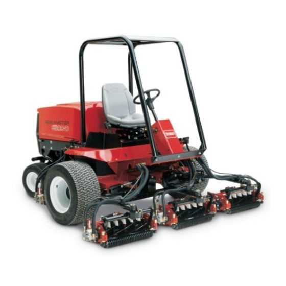
Reelmaster 6500-D/6700-D Models 03806, 03807 &
03808.
REFER TO THE TRACTION UNIT AND CUTTING
UNIT OPERATOR'S MANUALS FOR OPERATING,
MAINTENANCE AND ADJUSTMENT INSTRUC-
TIONS. For reference, insert a copy of the Operator's
Manual and Parts Catalog for your machine into Chap-
ter 2 of this service manual. Additional copies of the Op-
erator's Manual and Parts Catalog are available on the
internet at www.Toro.com.
The Toro Company reserves the right to change product
specifications or this publication without notice.
E The Toro Company - 2002, 2003, 2004, 2007, 2008
Reelmaster
NOTE:
For Machines With Serial Numbers Below 250000000: Use this book along with the Kubota Workshop Manu-
al, 05 Series Diesel Engine (Toro Part No. 01090SL) (Tier 1 Emission Engine Models).
R
6500-D/6700-D
This safety symbol means DANGER, WARNING,
or CAUTION, PERSONAL SAFETY INSTRUC-
TION. When you see this symbol, carefully read
the instructions that follow. Failure to obey the
instructions may result in personal injury.
NOTE: A NOTE will give general information about the
correct operation, maintenance, service, testing or re-
pair of the machine.
IMPORTANT: The IMPORTANT notice will give im-
portant instructions which must be followed to pre-
vent damage to systems or components on the
machine.
PART NO. 01084SL (Rev. F)
Service Manual
Advertisement
Table of Contents
Troubleshooting

Related Manuals for Toro Reelmaster 6500-D


Summary of Contents for Toro Reelmaster 6500-D
- Page 1 For Machines With Serial Numbers Below 250000000: Use this book along with the Kubota Workshop Manu- al, 05 Series Diesel Engine (Toro Part No. 01090SL) (Tier 1 Emission Engine Models). The purpose of this publication is to provide the service...
- Page 2 This page is intentionally blank. Reelmaster 6500-D/6700-D...
- Page 3 Wire Harness and Electrical Connector Drawings ....... 8 -- 17 Rev. F Reelmaster 6500-D/6700-D...
- Page 4 This page is intentionally blank. Reelmaster 6500-D/6700-D...
- Page 5 Maintenance and Service ..... Safety Instructions The REELMASTER 6500-D and 6700-D were tested and certified by TORO for compliance with the WARNING B71.4-1990 specifications of the American National...
- Page 6 D. Stop engine and remove key from switch. other hazard. E. Do not park on slopes unless wheels are chocked F. Reduce speed when making sharp turns and turn- or blocked. ing on a hillside. Safety Page 1 - 2 Rev. E Reelmaster 6500-D/6700-D...
- Page 7 Toro replacement parts and accessories. Replacement parts and accessories made 6. Before disconnecting or performing any work on the...
- Page 8 This page is intentionally blank. Safety Page 1 - 4 Reelmaster 6500-D/6700-D...
-
Page 9: Table Of Contents
Maintenance procedures and recommended service in- tervals for the Reelmaster 6500--D and 6700--D are cov- ered in the Operator’s Manual. Refer to that publication when performing regular equipment maintenance. Rev. E Reelmaster 6500-D/6700-D Page 2 - 1 Product Records and Maintenance... -
Page 10: Equivalents And Conversions
Equivalents and Conversions 0.09375 Rev. E Product Records and Maintenance Page 2 - 2 Reelmaster 6500-D/6700-D... -
Page 11: Torque Specifications
For critical applications, as determined reduced by 25% for lubricated fasteners to achieve by Toro, either the recommended torque or a torque that the similar stress as a dry fastener. Torque values may is unique to the application is clearly identified and spe- also have to be reduced when the fastener is threaded cified in this Service Manual. -
Page 12: Standard Torque For Dry, Zinc Plated, And Steel Fasteners (Inch Series)
+ 10% of the nominal torque value. Thin The specific torque value should be determined based height nuts include jam nuts. Rev. A Product Records and Maintenance Page 2 - 4 Reelmaster 6500-D/6700-D... -
Page 13: Standard Torque For Dry, Zinc Plated, And Steel Fasteners (Metric Series)
SAE J1199. The tolerance is approximately + 10% of the installing fasteners into threaded aluminum or brass. nominal torque value. The specific torque value should be determined based Rev. A Reelmaster 6500-D/6700-D Page 2 - 5 Product Records and Maintenance... - Page 14 -lb X 11.2985 = N- -cm N- -cm X 0.08851 = in- -lb ft- -lb X 1.3558 = N- -m N- -m X 0.7376 = ft- -lb Rev. A Product Records and Maintenance Page 2 - 6 Reelmaster 6500-D/6700-D...
- Page 15 ....Replace Fuel Prefilter ..... . . Reelmaster 6500-D/6700-D Page 3 - 1 Kubota Diesel Engine...
-
Page 16: Introduction
However, the cost of the maintenance, troubleshooting, testing, and repair of the test equipment and the specialized nature of some re- diesel engine used in the Reelmaster 6500-D and pairs may dictate that the work be done at an engine re- 6700-D. -
Page 17: Specifications
7.5 U.S. qts (7.0 l) with Filter Starter 12 VDC, 1.2 kW Alternator/Regulator 12 VDC 40 AMP Coolant Capacity 10 U.S. qt (9.4 l) with 1.0 U.S. qt (0.9 l) Reservoir Dry Weight 251.3 lbs (114 kg) Reelmaster 6500-D/6700-D Page 3 - 3 Kubota Diesel Engine... -
Page 18: General Information
FULL mark on the dipstick. Do not overfill. 1. Hood Latch Capacity is 7.5 qt. (7 L) with filter 5. Install oil fill cap and close hood. Figure 2 1. Dipstick Figure 3 1. Filler Cap Kubota Diesel Engine Page 3 - 4 Reelmaster 6500-D/6700-D... -
Page 19: Fill Fuel Tank
3. Fill fuel tank to about one inch below the top of the tank (not the filler neck) with No. 2 diesel fuel. Do not overfill. Fuel tank capacity is 15 U.S. Gallons (57 l). 4. Install cap. Reelmaster 6500-D/6700-D Page 3 - 5 Kubota Diesel Engine... -
Page 20: Check Cooling System
Reinstall vent plug using PTFE thread sealant. 6. Install radiator cap and expansion tank cap. 7. Close hood and secure latch. Kubota Diesel Engine Page 3 - 6 Rev. D Reelmaster 6500-D/6700-D... -
Page 21: Adjustments
40 to 55 in-lb (4.5 to 6.2 N-m). The maximum force required to operate the throttle lever should be 20 lb (9 kg). 7. Close hood and secure latch. Reelmaster 6500-D/6700-D Page 3 - 7 Kubota Diesel Engine... -
Page 22: Adjust Alternator Belt
4. Support Bracket 5. Gently pry alternator away from engine. 2. Bolt 5. Alternator 3. Bolt 6. When proper tension is achieved, tighten alternator bolts. 7. Close hood and secure latch. Kubota Diesel Engine Page 3 - 8 Reelmaster 6500-D/6700-D... -
Page 23: Service And Repairs
However, if the engine does not start, air may be trapped between injection pump and injectors (see Bleed Air from Fuel Injectors). 7. Close hood and secure latch. Reelmaster 6500-D/6700-D Page 3 - 9 Kubota Diesel Engine... -
Page 24: Bleed Air From Fuel Injectors
5. Add 10W-30 CD, CE, CF, CF-4, or CG-4 oil to crank- case. Capacity is 7.5 qt. (7 L) with filter. 6. Close hood and secure latch. Figure 13 1. Oil filter Kubota Diesel Engine Page 3 - 10 Reelmaster 6500-D/6700-D... -
Page 25: Clean Radiator And Oil Cooler
5. Close hood and secure latch. Figure 15 1. Oil Cooler 2. Radiator 6. Pivot oil cooler back into position and tighten knobs. Install rear screen and secure latches. Reelmaster 6500-D/6700-D Page 3 - 11 Kubota Diesel Engine... -
Page 26: Fuel Filter/Water Separator
2. Filter Element 7. O-ring 3. O-ring 8. Plug 4. Base 9. Pipe Plug 3. Clean area where filter element mates with base and 5. Plug 10. Drain Valve filter head. Kubota Diesel Engine Page 3 - 12 Reelmaster 6500-D/6700-D... -
Page 27: Replace Fuel Prefilter
7. Bleed air from fuel system (see Bleed Fuel System in this section of this manual). 8. Start engine and check for fuel leaks. 9. Close hood and secure latch. Reelmaster 6500-D/6700-D Page 3 - 13 Kubota Diesel Engine... -
Page 28: Fuel System
4. Round Head Screw 11. Fuel Elbow Connector 18. Flat Washer 5. Lock Washer 12. Grommet 19. Grommet 6. Sending Unit 13. Tank Cap 20. Frame 7. Gasket 14. Fuel Tank Kubota Diesel Engine Page 3 - 14 Reelmaster 6500-D/6700-D... -
Page 29: Check Fuel Lines And Connections
5. Remove fuel tank from the frame using Figure 19 as tions. a guide. 4. Install left fender and tool box to the frame. 5. Make sure drain fitting is closed. Fill fuel tank (see Fill Fuel Tank). Reelmaster 6500-D/6700-D Page 3 - 15 Kubota Diesel Engine... -
Page 30: Air Filter
8. Reinstall cover and secure latch. Reset indicator if is sealed properly by applying pressure to outer rim of showing red. filter when installing. Do not press on flexible center of filter. 9. Close hood and secure latch. Kubota Diesel Engine Page 3 - 16 Reelmaster 6500-D/6700-D... - Page 31 This page is intentionally left blank. Reelmaster 6500-D/6700-D Page 3 - 17 Kubota Diesel Engine...
-
Page 32: Radiator
9. Radiator Support 21. Knob 33. Lower Radiator Hose 10. Screw 22. O-ring 34. Screw 11. Reservoir Bracket 23. Hose Assembly 35. Flat Washer 12. Locknut 24. Hex Nut 36. Carriage Bolt Kubota Diesel Engine Page 3 - 18 Reelmaster 6500-D/6700-D... -
Page 33: Removal
10.Pull the bottom of the radiator away from the radiator support and slide the radiator out to the left side of the machine. 11. Plug any openings to prevent contamination. Reelmaster 6500-D/6700-D Page 3 - 19 Kubota Diesel Engine... - Page 34 45. Fuel Filter/Air Cleaner Support 22. Filter/Separator Bracket 46. Screw 70. Flat Washer 23. Screw 47. Flat Washer 71. Engine Assembly 24. Wire Harness 48. Lock Nut 72. Engine Bracket (front LH) Kubota Diesel Engine Page 3 - 20 Reelmaster 6500-D/6700-D...
- Page 35 B. Battery, frame, and wire harness ground to the engine block and the ETR solenoid (Fig. 29). 10.Disconnect and plug hydraulic lines and remove hy- draulic oil filter assembly and bracket. Reelmaster 6500-D/6700-D Page 3 - 21 Kubota Diesel Engine...
- Page 36 (Fig. 26). C. The temperature sender (Fig. 28). The oil low 8. Connect hydraulic lines at hydraulic pump assembly. pressure switch, starter, and alternator (Fig 27). 9. Connect all fuel hoses. Kubota Diesel Engine Page 3 - 22 Reelmaster 6500-D/6700-D...
- Page 37 16.Bleed air from fuel system (see Bleed Fuel System in this section of this manual). 17.Start engine and check for fuel leaks. 18.Close hood and secure latch. Reelmaster 6500-D/6700-D Page 3 - 23 Kubota Diesel Engine...
- Page 38 This page is intentionally left blank. Kubota Diesel Engine Page 3 - 24 Reelmaster 6500-D/6700-D...
- Page 39 ......Installing Hydraulic System Components ..Reelmaster 6500-D/6700-D Page 4 - 1 Rev. F...
-
Page 40: Specifications
Spin-on cartridge type with 50 PSI (3.4 bar) internal bypass Hydraulic Oil See Check Hydraulic System Fluid in General Information section Reservoir Capacity 8.5 gal. U.S. (32.2 L) System Capacity 10 gal. U.S. (37.8 L) Hydraulic System Page 4 - 2 Rev. B Reelmaster 6500-D/6700-D... - Page 41 0.75 + 0.25 8 (1/2 in.) 0.75 + 0.25 Finger Tight After Proper Tightening 10 (5/8 in.) 1.00 + 0.25 12 (3/4 in.) 0.75 + 0.25 16 (1 in.) 0.75 + 0.25 Figure 2 Reelmaster 6500-D/6700-D Page 4 - 3 Hydraulic System...
- Page 42 1.00 + 0.25 6 (3/8 in.) 1.50 + 0.25 8 (1/2 in.) 1.50 + 0.25 10 (5/8 in.) 1.50 + 0.25 12 (3/4 in.) 1.50 + 0.25 16 (1 in.) 1.50 + 0.25 Hydraulic System Page 4 - 4 Reelmaster 6500-D/6700-D...
-
Page 43: Pushing Or Towing Traction Unit
(32 L) hydraulic fluid. Check level of hydraulic fluid daily. See Operator’s Manual for fluid level check- ing procedure and hydraulic oil recommendations. Figure 8 1. Hydraulic Reservoir Cap Rev. F Reelmaster 6500-D/6700-D Page 4 - 5 Hydraulic System... -
Page 44: Hydraulic Schematics
Hydraulic Schematics Rev. F Hydraulic System Page 4 - 6 Reelmaster 6500-D/6700-D... - Page 45 Rev. F Reelmaster 6500-D/6700-D Page 4 - 7 Hydraulic System...
- Page 46 Rev. F Hydraulic System Page 4 - 8 Reelmaster 6500-D/6700-D...
- Page 47 Rev. F Reelmaster 6500-D/6700-D Page 4 - 9 Hydraulic System...
- Page 48 Rev. F Hydraulic System Page 4 - 10 Reelmaster 6500-D/6700-D...
- Page 49 Rev. F Reelmaster 6500-D/6700-D Page 4 - 11 Hydraulic System...
- Page 50 Rev. F Hydraulic System Page 4 - 12 Reelmaster 6500-D/6700-D...
- Page 51 12.1 Rev. F Reelmaster 6500-D/6700-D Page 4 - Hydraulic System...
- Page 52 12.2 Rev. F Hydraulic System Page 4 - Reelmaster 6500-D/6700-D...
- Page 53 12.3 Rev. F Reelmaster 6500-D/6700-D Page 4 - Hydraulic System...
- Page 54 12.4 Rev. F Hydraulic System Page 4 - Reelmaster 6500-D/6700-D...
- Page 55 Rev. F Reelmaster 6500-D/6700-D Page 4 - Hydraulic System...
-
Page 56: Hydraulic Flow Diagrams
Hydraulic Flow Diagrams Hydraulic System Page 4 - 14 Reelmaster 6500-D/6700-D... -
Page 57: Traction Circuit
250 PSI (17.2 bar) by a relief valve (R5). Operating pressure on the high pressure side of the closed drive circuit is determined by the amount of load Reelmaster 6500-D/6700-D Page 4 - 15 Rev. C Hydraulic System... - Page 58 Hydraulic System Page 4 - 16 Rev. B Reelmaster 6500-D/6700-D...
-
Page 59: Lower Cutting Units
(G3). valve regulates cylinder #1, the second controls cylin- ders #2 and 3, the third controls cylinders #4 and 5, the fourth controls cylinder #6 and the fifth controls cylinder Reelmaster 6500-D/6700-D Page 4 - 17 Rev. F Hydraulic System... - Page 60 Hydraulic System Page 4 - 18 Rev. B Reelmaster 6500-D/6700-D...
-
Page 61: Raise Cutting Units
An electrically activated flow di- vider (FD1) is also de-energized, preventing flow be- tween the #4 and 5 lift cylinders. Reelmaster 6500-D/6700-D Page 4 - 19 Rev. C Hydraulic System... - Page 62 Hydraulic System Page 4 - 20 Rev. B Reelmaster 6500-D/6700-D...
-
Page 63: Mow And Backlap
(MD1) or (MD2) is set to the “Backlap” position, Port (G1). the valve reverses the direction of hydraulic flow through the reel motors, and the reels rotate correctly for back- lapping. Reelmaster 6500-D/6700-D Page 4 - 21 Rev. C Hydraulic System... - Page 64 Hydraulic System Page 4 - 22 Reelmaster 6500-D/6700-D...
-
Page 65: Right And Left Turns
(LH) port to the rod end of the steering cylin- through the OUT port, travels to the lift manifold, and re- der. The rotary meter ensures that the oil flow to the cyl- turns to the hydraulic reservoir. Reelmaster 6500-D/6700-D Page 4 - 23 Hydraulic System... -
Page 66: Special Tools
Special Tools NOTE: Order special tools from your Toro Distributor. Some tools may also be available from a local supplier. Hydraulic Pressure Test Kit - TOR47009 Use to take various pressure readings for diagnostic tests. Quick disconnect fittings provided attach directly to mating fittings on machine test ports without tools. - Page 67 0 - 1000 PSI. This gauge has a protector valve which cuts out when pressure is about to exceed the normal range for the gauge. The cutout pressure is adjustable. Reelmaster 6500-D/6700-D Page 4 - 25 Hydraulic System...
-
Page 68: Troubleshooting
TEST NO. 1. Inspect charge relief valve R5. Repair or replace if defective. Servo control valve faulty. Inspect control valve for: Missing center orifice. Plugged control orifices. Galled or stuck control spool. Repair or replace control valve if necessary. Hydraulic System Page 4 - 26 Reelmaster 6500-D/6700-D... - Page 69 Transmission relief valve faulty. TEST NO. 2. Inspect relief valves R6 and replace if necessary. NOTE: Relief valves can be exchanged in forward and reverse pump circuits for testing. Pump worn or damaged. Replace pump. Reelmaster 6500-D/6700-D Page 4 - 27 Hydraulic System...
- Page 70 Inspect control valve for: Plugged control orifices. Damaged mounting gasket. Misadjusted or damaged neutral return spring. Broken control connector pin. Galled or stuck control spool. Neutral switch misadjusted. Repair or replace control valve if necessary. Hydraulic System Page 4 - 28 Reelmaster 6500-D/6700-D...
- Page 71 TEST NO. 1. Inspect charge relief valve R5. Repair or replace if defective. Scored valve plate or piston shoes on wheel motor. Disassemble motor and inspect valve plate and piston shoes. Replace as required. Reelmaster 6500-D/6700-D Page 4 - 29 Hydraulic System...
- Page 72 Test solenoid coil. Replace if faulty. See Chapter 5 - Electrical System. Do cartridge valve service procedure for valve MSV1 (MSV2). Interchange MSV1 and MSV2 and check operation. Replace faulty valve. Rev. E Hydraulic System Page 4 - 30 Reelmaster 6500-D/6700-D...
- Page 73 Replace faulty valve. Relief valve R1 (R2) by-passing oil. TEST NO. 3. Adjust relief valve R1 (R2) if necessary. Do cartridge valve service procedure for valve R1 (R2). Replace faulty valve. Rev. E Reelmaster 6500-D/6700-D Page 4 - 31 Hydraulic System...
- Page 74 Decrease load. Electrical problem. See Chapter 5 - Electrical System. Reel motor internal leakage (by-passing oil) or TEST NO. 6 & 7. Repair or replace reel motor. malfunctioning cross-over relief valve in motor. Hydraulic System Page 4 - 32 Reelmaster 6500-D/6700-D...
- Page 75 Electrical System. Do cartridge valve service procedure for valve in affected circuit. Interchange suspect valve with any of the remaining valves (SV3 thru SV7) and check operation. Replace faulty valve. Rev. E Reelmaster 6500-D/6700-D Page 4 - 33 Hydraulic System...
- Page 76 Check lift cylinder(s) and repair or replace if faulty. Cutting Units Lower Too Fast or Too Slow Cause Correction Flow control valve(s) not adjusted properly. Adjust flow control valve(s) to desired lowering speed. Hydraulic System Page 4 - 34 Reelmaster 6500-D/6700-D...
- Page 77 Do cartridge valve service procedure for valve SV2. Replace faulty valve. Relief valve R3 by-passing oil. TEST NO. 4. Replace faulty valve. Flow control valve(s) closed. Adjust flow control valve(s) to desired lowering speed. Rev. E Reelmaster 6500-D/6700-D Page 4 - 35 Hydraulic System...
-
Page 78: Testing
Stop engine; 9. Check control linkages for improper adjustment, lower or support attachments. binding, or broken parts. 10.All hydraulic tests should be made with the hydraulic oil at normal operating temperature. Hydraulic System Page 4 - 36 Reelmaster 6500-D/6700-D... -
Page 79: Test No. 1: Traction Circuit Charge Pressure
When the pump is worn or damaged the charge pump is not able to keep up with the internal leakage. Reelmaster 6500-D/6700-D Page 4 - 37 Hydraulic System... -
Page 80: Test No. 2: Traction Circuit Pressure
Clean or replace valves as necessary. These cartridge type valves are factory set, and are not adjust- able. If relief valves are in good condition, traction pump or wheel motors should be suspected of wear and ineffi- ciency. Hydraulic System Page 4 - 38 Reelmaster 6500-D/6700-D... -
Page 81: Test No. 3: Cutting Unit Drive Circuit Pressure
1500 to 1800 PSI. and the rear sonal injury from rotating reel blades. circuit should operate at 1000 to 1200 PSI. for 6500-D and at maximum circuit pressure for 6700-D. Reelmaster 6500-D/6700-D Page 4 - 39 Rev. B Hydraulic System... -
Page 82: Test No. 4: Gear Pump Section P3 Flow And Relief Valve Pressure
METER READING: 1500 +/- 50 PSI. 8. If pressure is maintained below 1450 PSI or pressure goes beyond 1550 PSI, replace the relief valve. 9. Stop engine. Remove tester and reinstall hoses. Hydraulic System Page 4 - 40 Reelmaster 6500-D/6700-D... -
Page 83: Test No. 5: Gear Pump Section P1 & P2 Flow
NOT engage the cutting units. 5. While watching pressure gauges, slowly close the tester flow control valve until 2000 PSI is obtained on gauge. METER READING: 7 GPM or more at 2000 PSI. Reelmaster 6500-D/6700-D Page 4 - 41 Hydraulic System... -
Page 84: Test No. 6: Reel Drive Motor Cross-Over Relief Pressure
Keep away from reels during tests to prevent personal injury from rotating blades. Do not 1. Make sure hydraulic oil is at normal operating temper- stand in front of the machine. ature before doing test. Hydraulic System Page 4 - 42 Reelmaster 6500-D/6700-D... - Page 85 6. With cutting units in lowered position and engine OFF, insert a block of wood between cutting unit reel blades and front cross tube of cutting unit to prevent reel from turning (Fig. 19). Reelmaster 6500-D/6700-D Page 4 - 43 Hydraulic System...
-
Page 86: Test No. 7: Reel Drive Motor Efficiency
Hydraulic System Page 4 - 44 Reelmaster 6500-D/6700-D... - Page 87 11. If flow is less than .7 GPM, disconnect tester from not stand in front of the machine. motor and hose. Reconnect hose to the reel motor. Re- move plug from machine. Reconnect case drain hose to the reel motor. Reelmaster 6500-D/6700-D Page 4 - 45 Hydraulic System...
-
Page 88: Adjustments
3. To DECREASE pressure setting, turn the adjust- ment socket inside the valve 1/8 of a turn counterclock- wise. 4. Install and tighten cap to valve. Retest pressure set- ting (see Testing). Hydraulic System Page 4 - 46 Rev. C Reelmaster 6500-D/6700-D... -
Page 89: Adjust Traction Drive For Neutral
6. Stop the engine and release the right brake. Remove jack stands and lower the machine to the shop floor. Test drive the machine to make sure it does not creep. Reelmaster 6500-D/6700-D Page 4 - 47 Hydraulic System... -
Page 90: Adjust Cutting Unit Drop Rates (Serial Numbers Below 280000000)
MANIFOLD Figure 25 1. Center front (#1) 4. 6700- -D LH rear (#6) 2. Outside front (#4 & #5) 5. 6700- -D RH rear (#7) 3. Rear (#2 & #3) Rev. F Hydraulic System Page 4 - 48 Reelmaster 6500-D/6700-D... -
Page 91: Service And Repairs
5. Note the position of hydraulic fittings (especially el- bow fittings) on hydraulic components before removal. Mark parts if necessary to make sure they will be aligned properly when reinstalling hydraulic hoses and tubes. Reelmaster 6500-D/6700-D Page 4 - 49 Hydraulic System... -
Page 92: Check Hydraulic Lines And Hoses
5. Inspect and clean hydraulic reservoir (see Hydraulic Reservoir Inspection). 16.Assume normal operation and follow recommended maintenance intervals. 6. Reconnect all hydraulic hoses, lines, and compo- nents that were disconnected while draining system. Rev. F Hydraulic System Page 4 - 50 Reelmaster 6500-D/6700-D... -
Page 93: Charge Hydraulic System
Start engine and run it at low idle of 1150 rpm. The charge pump should pick up oil and fill the hydraulic system. If there is no indication of fill in 30 seconds, stop the engine and determine the cause. Rev. F Reelmaster 6500-D/6700-D Page 4 - 51 Hydraulic System... -
Page 94: Change Hydraulic Fluid
Change Hydraulic Fluid Change hydraulic fluid after every 800 operating hours, in normal conditions. If fluid becomes contaminated, contact your local TORO distributor because the system must be flushed. Contaminated fluid looks milky or black when compared to clean oil. -
Page 95: Replace Hydraulic Oil Filter
GREEN zone. When the indicator is in the RED zone, the filter element should be changed. IMPORTANT: Use only the Toro replacement filter recommended for this product (see parts catalog or service reference decal on unit). Use of any other fil- ter may void the warranty on some components. -
Page 96: Piston Pump (Traction Pump)
57. Charge Pump Relief Valve 17. Relief Valve 38. Control Valve Orifice 58. Spring 18. Screw 39. Cradle Assembly 59. Shims 19. Screw 40. Coupler 60. O-ring 20. Screw 21. Screw 41. Retaining Ring 61. Plug Hydraulic System Page 4 - 54 Reelmaster 6500-D/6700-D... -
Page 97: Disassembly
(Hole in table, for protruding shaft, is required.) Lift and remove the housing and shaft from rotating kit assem- bly, and camplate. 11. Remove camplate (14) from rotating kit assembly. Remove piston follower (8) from camplate. Figure 29 Reelmaster 6500-D/6700-D Page 4 - 55 Hydraulic System... -
Page 98: Assembly
Holding servo piston bolt with hex bly. key wrench. Tighten nut to 150 to 160 in-lbs. (17 to 17. Remove screw (52) to remove cradle bushing from 18 Nm). cradle. Hydraulic System Page 4 - 56 Reelmaster 6500-D/6700-D... - Page 99 28. Install new O-rings (56) on all plugs (53) and install plugs into housing. Tighten 3/4 in. plugs to 21 to 24 ft-lbs. (28 to 32 Nm). Tighten 1-1/4 in. plugs to 40 to 45 ft-lbs. (54 to 61 Nm). Reelmaster 6500-D/6700-D Page 4 - 57 Hydraulic System...
-
Page 100: Servo Control
Clean all parts and lubricate in prep for reassembly. (23) in position with feedback link slot and align splined hole of bell crank with input shaft cavity. Install input shaft (8) into control housing and bell crank (23). Hydraulic System Page 4 - 58 Reelmaster 6500-D/6700-D... -
Page 101: Neutral Lockout Switch Assembly
“B” and “A”. Install and tighten the hex socket head set screw in one of the upper quadrants of the hex of the switch adapter (Fig. 34). Tighten set screw to 28 to 34 in-lbs. (3.2 to 3.8 Nm). Reelmaster 6500-D/6700-D Page 4 - 59 Hydraulic System... -
Page 102: Gear Pump
7. Plug 17. Gear 27. Backup Washer 8. Front Plate Assembly 18. Idler Gear 28. O-ring 9. Copper Washer 19. Key 29. O-ring 10. Screw 20. Front Adapter Plate 30. Backplate Assembly Hydraulic System Page 4 - 60 Reelmaster 6500-D/6700-D... -
Page 103: Disassembly
7. If edge of gear teeth are sharp, break edge with the rear adapter plate. emery cloth. 13. Remove the wear plates (4) from front plate (8), front adapter plate (20), and rear adapter plate (21). Reelmaster 6500-D/6700-D Page 4 - 61 Hydraulic System... -
Page 104: Assembly
6. Apply a thin coat of petroleum jelly to both milled gear pockets of front body (2). Slip body onto front plate with 22. Install key on keyed shaft. half moon port cavities in body facing away from front plate. Hydraulic System Page 4 - 62 Reelmaster 6500-D/6700-D... - Page 105 This page is intentionally blank. Reelmaster 6500-D/6700-D Page 4 - 63 Hydraulic System...
-
Page 106: Wheel Motor
3. Remove valve plate (15) and O-ring (10) from back- backplate (10) and replace if necessary. plate. It is not necessary to remove roll pins in backplate. 4. Remove motor from vise and remove rotating assem- bly (16) from motor housing. Hydraulic System Page 4 - 64 Reelmaster 6500-D/6700-D... - Page 107 (2), and retaining ring (1). 5. Install camplate insert (17) with the lettering side of in- sert to the front of the housing. Use petroleum jelly to hold in place during assembly. Reelmaster 6500-D/6700-D Page 4 - 65 Hydraulic System...
-
Page 108: 4Wd Rear Axle Motor
3. Use a mallet and tap the backplate (8) to loosen and remove from housing. 4. Remove valve plate (13) and O-ring (9) from back- plate. It is not necessary to remove roll pins in backplate. Rev. E Hydraulic System Page 4 - 66 Reelmaster 6500-D/6700-D... - Page 109 (1). 5. Install camplate insert (15) with the lettering side of in- sert to the front of the housing. Use petroleum jelly to hold in place during assembly. Rev. E Reelmaster 6500-D/6700-D Page 4 - 67 Hydraulic System...
-
Page 110: Reel Motor (Barnes)
2. Tighten motor mounting nuts. 3. Remove caps or plugs from fittings and hoses. Con- nect hydraulic lines lines to the motor. Hydraulic System Page 4 - 68 Rev. E Reelmaster 6500-D/6700-D... -
Page 111: Adjusting Valve (Cross-Over Relief Valve) Service
9. Before removing gear set, apply marking dye to mat- ing teeth to retain “timing”. Motor efficiency may be af- fected if the teeth are not installed in the same position during reassembly. Reelmaster 6500-D/6700-D Page 4 - 69 Hydraulic System... -
Page 112: Assembly
11. Front Flange 17. Back- -up Ring 5. Pressure Seal 12. Dowel Pin 18. Relief Cartridge 6. Back- -up Ring 13. Rear Bearing Block 19. Retaining Ring 7. O- -ring Rev. E Hydraulic System Page 4 - 70 Reelmaster 6500-D/6700-D... - Page 113 15.Remove motor from vise. 1. Lubricate new o--rings, pressure seals, back--up gaskets and seal grooves with a thin coat of petroleum jelly. Lubricate all other internal parts freely with clean hydraulic oil. Rev. E Reelmaster 6500-D/6700-D Page 4 - 71 Hydraulic System...
-
Page 114: Hydraulic Control Manifolds
Service and Repairs section of this chap- ter. 1. Disconnect all electrical connectors from solenoid valves and switches. 2. Disconnect all hydraulic tubes and hoses. 3. Remove hydraulic manifold from the frame (Fig. 43). Hydraulic System Page 4 - 72 Reelmaster 6500-D/6700-D... -
Page 115: Lift Manifold Removal And Installation
4. Install lift manifold in reverse order. Note: Read the General Precautions for Removing and Installing Hydraulic System Components at the be- ginning of the Service and Repairs section of this chap- ter. Reelmaster 6500-D/6700-D Page 4 - 73 Hydraulic System... - Page 116 P1 is the gear pump connec- tion port (See Hydraulic Schematics to identify the func- tion of the hydraulic lines and cartridge valves at each port location). Rev. E Hydraulic System Page 4 - 74 Reelmaster 6500-D/6700-D...
- Page 117 When installing plugs into the control manifold, torque plugs to the values identified in Figure Rev. F Reelmaster 6500-D/6700-D Page 4 - 75 Hydraulic System...
- Page 118 Example: P1 and P2 are the gear pump connection ports (See Hydraulic Schematics to identify the function of the hydraulic lines and cartridge valves at each port location). Rev. F Hydraulic System Page 4 - 76 Reelmaster 6500-D/6700-D...
- Page 119 When installing plug into the control manifold, torque plug 25 ft- -lb (33 N- -m). 76.1 Rev. F Reelmaster 6500-D/6700-D Page 4 - Hydraulic System...
- Page 120 When installing plug into the control manifold, torque plug 25 ft- -lb (33 N- -m). 76.2 Rev. F Hydraulic System Page 4 - Reelmaster 6500-D/6700-D...
-
Page 121: Valves
5 or 6 times. Particles as fine as talcum powder D. Loosen two (2) set screws that secure handle can affect the operation of high pressure hydraulic base to flow control valve and remove base. valves. Remove solenoid. Rev. E Reelmaster 6500-D/6700-D Page 4 - 77 Hydraulic System... - Page 122 1/4 turn. ”1” on the locating plate. D. Center one detent plate hole over a locating plate indentation. Drop a ball into each hole, then drop a spring into each hole. Rev. E Hydraulic System Page 4 - 78 Reelmaster 6500-D/6700-D...
-
Page 123: Mow/Backlap Spools
A. Remove backlap switch from mow manifold be- fore removing mow/backlap spool. Remove dowel pin and ball from manifold port after switch is re- moved. Remove and discard o--ring from switch. Rev. E Reelmaster 6500-D/6700-D Page 4 - 79 Hydraulic System... -
Page 124: Lift Cylinders
(Fig. 51). C. Install in reverse order. Figure 51 1. Retaining Ring 4. Retaining Ring 2. Thrust Washer 5. Cylinder Cap End Pin 3. Cylinder Rod End Pin 6. Lift Arm Hydraulic System Page 4 - 80 Reelmaster 6500-D/6700-D... - Page 125 Figure 52 1. Lock Nut 5. Retaining Ring 2. Upper Link Plate 6. Cylinder Cap End Pin 3. Upper Link 7. Lift Arm 4. Roller 8. Lower Link Plate Reelmaster 6500-D/6700-D Page 4 - 81 Hydraulic System...
-
Page 126: Lift Cylinder Service
1. Barrel with Clevis 5. O-ring 10. Dust Seal 2. Nut 6. Rod Seal 11. Collar 3. Uni-ring 7. O-ring 12. Shaft with Clevis 4. Piston 8. Back-up Ring 13. Grease Fitting 9. Head Hydraulic System Page 4 - 82 Reelmaster 6500-D/6700-D... - Page 127 Remove lock nut and piston from the shaft and into head. shaft. Slide head off the shaft. 5. Remove Uni-ring and O-ring from the piston. Re- move O-ring, back-up ring, rod seal, and dust seal from the head. Reelmaster 6500-D/6700-D Page 4 - 83 Hydraulic System...
-
Page 128: Steering Cylinder (2Wd)
1. Barrel with Clevis 5. Nut 9. O-ring 2. Piston Rod 6. Retaining Ring 10. Rod Seal 3. Piston 7. Dust Seal 11. O-ring 4. Gland 8. Uni- -ring 12. Backup Ring Rev. E Hydraulic System Page 4 - 84 Reelmaster 6500-D/6700-D... - Page 129 6. Securely mount piston, piston rod, and head into vise 4. Slide piston rod assembly into cylinder tube. and remove nut. 5. Install gland and retaining ring. Rev. E Reelmaster 6500-D/6700-D Page 4 - 85 Hydraulic System...
-
Page 130: Steering Cylinder (4Wd)
Steering Cylinder (4WD) Figure 55 1. Barrel with Clevis 5. O-ring 9. Piston Rod Assembly 2. PTFE Seal 6. U-cup 10. O-ring 3. O-ring 7. Gland 11. Locknut 4. Piston 8. Wiper Rev. D Hydraulic System Page 4 - 86 Reelmaster 6500-D/6700-D... - Page 131 3. Put a coating of oil on all cylinder parts to ease as- IMPORTANT: Do not clamp vise jaws against the sembly. shaft surface. Protect shaft surface before mount- 4. Slide piston rod assembly into cylinder tube and ing in a vice. install gland. Reelmaster 6500-D/6700-D Page 4 - 87 Hydraulic System...
-
Page 132: Power Steering
9. Hydraulic tube 15. Hydraulic tube 4. Dust cover 10. Hydraulic tube 16. Hydraulic tube 5. Steering column 11. Steering valve 17. Flange head screw (3 used) 6. Clamp 12. O- -ring Rev. E Hydraulic System Page 4 - 88 Reelmaster 6500-D/6700-D... -
Page 133: Steering Valve
1. Carefully feed the steering valve and column into the steering tower through the bottom. 2. Install three (3) flange head screws and the clamp securing steering valve to steering tower. Rev. E Reelmaster 6500-D/6700-D Page 4 - 89 Hydraulic System... -
Page 134: Steering Valve Service
The centering springs are under tension. Re- (Fig. 60). move the retaining ring carefully. 4. Remove the thrust bearing and bearing races. 9. Remove the retaining ring and springs. 5. Remove the quad seal. Hydraulic System Page 4 - 90 Reelmaster 6500-D/6700-D... - Page 135 D. Fit the quad seal into its seat through the input end of the housing. Be sure the seal is not twisted. E. Remove the sleeve and bearing race. 2. Lubricate and install the dust seal (Fig. 62). Reelmaster 6500-D/6700-D Page 4 - 91 Hydraulic System...
- Page 136 (16 - 18 Nm). 20.Remove the steering control unit from the vise. 21.Install the check ball and plug. Use a new o-ring and tighten the plug to 150 in-lb (17 Nm). Rev. E Hydraulic System Page 4 - 92 Reelmaster 6500-D/6700-D...
-
Page 137: Solenoid Valve Sv10 And Sv11 Service (Rm 6700-D Only)
Contamination can become lodged in small valve orifices or seal areas causing malfunction. B. If sealing surfaces appear pitted or damaged, the hydraulic system may be overheating or there may be water in the system. Reelmaster 6500-D/6700-D Page 4 - 93 Hydraulic System... -
Page 138: Hydraulic Reservoir
24. Hydraulic Tube 38. O-ring 11. O-ring 39. Straight Hydraulic Fitting 25. Grommet 12. Hydraulic Tube 26. Flat Washer 40. O-ring 13. O-ring 27. Capscrew 41. Hydraulic Tube 14. Tee Hydraulic Fitting 28. Support Hydraulic System Page 4 - 94 Reelmaster 6500-D/6700-D... - Page 139 4. Remove oil tank. 5. Fill reservoir with hydraulic fluid (see Change Hy- Inspection draulic Fluid). 1. Clean hydraulic reservoir and suction strainer with solvent. 2. Inspect hydraulic reservoir for leaks, cracks, or other damage. Reelmaster 6500-D/6700-D Page 4 - 95 Hydraulic System...
-
Page 140: Hydraulic Oil Cooler
3. Plug both ends of oil cooler. Clean exterior of cooler. Make sure fins are clear of dirt and debris. 4. The oil cooler should be free of corrosion, cracked tubes, and excessive pitting of tubes. Hydraulic System Page 4 - 96 Reelmaster 6500-D/6700-D... - Page 141 ..... . . Installing Optional Lighting ....Reelmaster 6500-D/6700-D Electrical System (Rev. C) Page 5 - 1...
-
Page 142: Special Tools
The meter can test electrical components and circuits for current, resistance, or voltage drop. NOTE: Toro recommends the use of a DIGITAL multi- meter when testing electrical circuits. The high imped- ance (internal resistance) of a digital meter will ensure that excess current is not allowed through the meter. - Page 143 This device can record machine data while it is in operation to help your Toro Distributor diagnose intermittent problems. Contact you local authorized Toro distributor for infor- mation on obtaining this service or device. Figure 5 Reelmaster 6500-D/6700-D Electrical System (Rev.
-
Page 144: Troubleshooting
Leak - Diagnostic ACE (with the correct overlay). Detector - TOROPC and a personal computer (Optional) (authorized Toro distributor only). Audible - Data Log System. diagnostic alarm Figure 6 Secondary Controller (#2) - RM6700-D Only... -
Page 145: Understanding The Diagnostic Lamps
S Alerts operator to several potential problems with - Diagnostic ACE (with the correct overlay). audible “beeps” and/or by cutting unit shut down. - TOROPC and a personal computer Diagnostics: (authorized Toro distributor only). Understanding the Diagnostic Lamps Red Diagnostic Lamp (located on steering tower) Functions: S ON - When glow plug circuit is energized. -
Page 146: Using The Acet Diagnostic Display
3. Check Input Functions (Interlock Switches) Note: For checking optional TurfDefender leak de- tector, see Leak Detector Operation and Checking Leak Detector Operation in this section of this manu- Electrical System (Rev. C) Reelmaster 6500-D/6700-D Page 5 - 6... - Page 147 Ma- lem. If this occurs, contact your Toro Distributor for chine will not operate without loop-back connector assistance. installed on harness. Store Diagnostic ACE in dry, secure location in shop, not on machine.
-
Page 148: Turfdefendertleak Detector
Reelmaster electronic controller has shut off the cutting unit’s. Electrical System (Rev. C) Reelmaster 6500-D/6700-D Page 5 - 8... - Page 149 Float position (1 or 2 LED’s on left side) and “Oil level held Diagnostic ACE. A leakdown test is required to OK” LED (right side) -- should be displayed (Fig. 14). identify small air leaks. Consult your Authorized Toro Distributor for assistance. 2. Press toggle button until green “Outputs displayed”...
- Page 150 3. Air leak in system. Check to make sure cap is secure- nect loopback connectors to harness connectors. ly on tank. Contact your local authorized Toro Distributor Machine will not operate without loopback connec- for further assistance with air leak problem.
- Page 151 “Self Diagnostic” LED lit steadily c. “DATA LINE” LED lit steadily d. “Alarm ON” LED lit temporarily Problem Diagnosed: The appropriate LED will blink to identify the problem Figure 15 Reelmaster 6500-D/6700-D Electrical System (Rev. C) Page 5 - 11...
-
Page 152: Leak Detector Troubleshooting Guide
Solenoid valve unplugged Reconnect Hydraulic tank cap is loose Tighten Reelmaster Electronic Controller has wrong program- Contact an Authorized Toro Distributor ming installed False-Alarms (continuous beeps but no leak) are Occurring Hydraulic tank cap is loose Tighten Operator is making severe left turns... -
Page 153: Starting Problems
The problem is not electrical (see Chapter 3 - Kubota Diesel Engine). Start cranks, but should not when the traction is The traction neutral switch is out of adjustment. depressed. The traction neutral switch or circuit wiring is faulty. Reelmaster 6500-D/6700-D Electrical System (Rev. C) Page 5 - 13... -
Page 154: General Run And Transport Problems
The fusible link to the battery is faulty. Alternator belt slipping. Faulty alternator or battery. Alternator warning lamp is faulty or burned out. Alternator warning lamp wiring loose, corroded, or damaged. Electrical System (Rev. C) Reelmaster 6500-D/6700-D Page 5 - 14... -
Page 155: Cutting Unit Operation Problems
Outer front cutting units #4 and 5 will not lower. Flow divider FD1 solenoid (if equipped) or circuit wiring is faulty. A hydraulic problem exists (see Troubleshooting section of Chapter 4 - Hydraulic System). Reelmaster 6500-D/6700-D Electrical System (Rev. C) Page 5 - 15... - Page 156 Chapter 4 - Hydraulic System). The rear cutting units do not backlap, but all cutting The rear backlap switch or circuit wiring is faulty. units run in the forward direction. Electrical System (Rev. C) Reelmaster 6500-D/6700-D Page 5 - 16...
-
Page 157: Electrical System Quick Checks
Turn on the cir- cuit to be tested and read the voltage. Remember - when performing voltage drop tests the circuit must be com- plete and activated to locate the resistance! Reelmaster 6500-D/6700-D Electrical System (Rev. C) Page 5 - 17... -
Page 158: Glow Plug System Test
3 seconds and record the results. Typ- Note: The Battery condition and state of charge must ical Starter System Draw for the Reelmaster 6500-D checked before testing the starter system. and 6700-D is 225 Amps at 65_F. -
Page 159: Component Testing
POSITION CIRCUIT NONE B + I + A, X + Y START B + I + S Figure 16 1. Key 3. Lock washer 2. Hex nut 4. Ignition switch Reelmaster 6500-D/6700-D Electrical System (Rev. C) Page 5 - 19... -
Page 160: Glow And Start Relays
30 and 87 should read as an open circuit. B. For the start relay, resistance between terminals 30 and 87A should be 1 ohm or less. 4. Disconnect voltage and leads from all terminals. Electrical System (Rev. C) Reelmaster 6500-D/6700-D Page 5 - 20... -
Page 161: Fuses
Controller connector terminal B on RM 6700- D. Fuse 3B (When Optional Lighting is Installed) B. Has two red wires. A. Supplies power to light relay terminal 1. B. Has two red wires. Reelmaster 6500-D/6700-D Electrical System (Rev. C) Page 5 - 21... -
Page 162: Hydraulic Valve Solenoids
Lift/lower rear cutting unit #7 (6700-D only) Yellow/White Lower any cutting units (if equipped) SV8 (if equipped) White/Black Lift/lower front outer cutting units #4 & 5 Orange/Red 6. Reconnect electrical connector to the solenoid. Electrical System (Rev. C) Reelmaster 6500-D/6700-D Page 5 - 22... -
Page 163: High Temperature Warning And Shutdown Switch
C. Connect green/white wire to sender. Apply skin- over grease to sender terminal. 7. Fill engine cooling system (see Check Cooling Sys- tem in Chapter 3 - Kubota Diesel Engine). Reelmaster 6500-D/6700-D Electrical System (Rev. C) Page 5 - 23... -
Page 164: Warning Light Cluster
1. Turn ignition switch to ON; the light should come on. 2. Turn ignition switch to OFF: the light should go off. Electrical System (Rev. C) Reelmaster 6500-D/6700-D Page 5 - 24... -
Page 165: Run (Etr) Solenoid (Solenoid With 3 Wire Connector)
The solenoid should stay engaged. 6. Remove positive (+) voltage from the pin of the red/ blue wire. The solenoid should release. 7. Reconnect the wires to the solenoid. Reelmaster 6500-D/6700-D Electrical System (Rev. C) Page 5 - 25... -
Page 166: Run (Etr) Solenoid (Solenoid With 2 Wire Connector)
5. Remove positive (+) voltage from the pull coil termi- nal. The solenoid should stay engaged. 6. Remove positive (+) voltage from the hold coil termi- nal. The solenoid should release. 7. Reconnect the wires to the solenoid. Electrical System (Rev. C) Reelmaster 6500-D/6700-D Page 5 - 26... -
Page 167: Fuel Gauge Sender
5. Fuel tank 5. Replace sender as necessary. Reinstall sender into 3. Fuel sender fuel tank. Connect wires. 7.62 inch 100_ (19.4 cm) Figure 32 1. Full position 2. Empty position Reelmaster 6500-D/6700-D Electrical System (Rev. C) Page 5 - 27... -
Page 168: Fuel Gauge
(full). 3. Turn off the voltage source. Disconnect voltage source, gauge, and variable resistance. Figure 34 1. Empty position 3. Glass face edge 2. Full position Electrical System (Rev. C) Reelmaster 6500-D/6700-D Page 5 - 28... -
Page 169: Temperature Sender
C. Connect blue/white wire to sender. Apply skin- over grease to sender terminal. 5. Fill engine cooling system (see Check Cooling Sys- tem in Chapter 3 - Kubota Diesel Engine). Reelmaster 6500-D/6700-D Electrical System (Rev. C) Page 5 - 29... -
Page 170: Temperature Gauge
(105_C). 3. Turn off the voltage source. Disconnect voltage source, gauge, and variable resistance. Figure 38 1. Middle position 3. Edge of glass cover 2. High temp position Electrical System (Rev. C) Reelmaster 6500-D/6700-D Rev. E Page 5 - 30... -
Page 171: Hourmeter
4. Disconnect voltage source from the hour meter. BACK Figure 39 Electronic Controller(s) The Toro electronic controller(s) sense the condition of various switches, such as the seat sensor, cutting unit down switches, traction neutral switch, etc., and directs power output to allow certain machine functions, such as engine run, cutting units engage, etc. -
Page 172: Engine Low Oil Pressure Switch
LED on the diagnostic tool should blink On and Off. Figure 42 IMPORTANT: When replacing the sensor, see Speedometer Sensor Replacement in this section of 1. Speedometer sensor this manual. Electrical System (Rev. C) Reelmaster 6500-D/6700-D Page 5 - 32... -
Page 173: Speedometer
(CU #1 - 5) switch 2. Reel enable/disable (RM 6700-D CU #7) terminals. switch (RM 6700-D CU #6) These switches can be tested using the “Input Checks” feature of the ACE Diagnostic tool. Reelmaster 6500-D/6700-D Electrical System (Rev. C) Page 5 - 33... -
Page 174: Reel Backlap Switches
Allow the traction pedal to return to neutral. There should be continuity across the terminals. See Chapter 4 - Hydraulic System in this manual for replacement and adjustment procedures. Electrical System (Rev. C) Reelmaster 6500-D/6700-D Rev. E Page 5 - 34... -
Page 175: Seat Sensor
Figure 48 1. Joy stick 3. Lift control mechanism 2. Micro switch Reelmaster 6500-D/6700-D Electrical System (Rev. C) Rev. E Page 5 - 35... -
Page 176: Cutting Unit Down Sensors
(Located on frame rails) tem in this manual). 1. #6 reel solenoid (S10) 2. #7 reel solenoid (S11) Solenoid coil resistance: 3. Rear valve block 3.5 Ohms (+ 10%) at 77_F (25_C) Electrical System (Rev. C) Reelmaster 6500-D/6700-D Page 5 - 36... -
Page 177: Service And Repairs
B. Coat battery posts and cable connectors with tained. The top of the battery must be kept clean. lf the Grafo 112X (skin-over) grease (Toro Part No. machine is stored in a location where temperatures are 505-165) or petroleum jelly to prevent corrosion. -
Page 178: Battery Service
(37.7_C minus 26.7_C equals 11.0_C) service area to allow better access for service. 20_F multiply by 0.004/10_F equals 0.008 multiply by 0.004/5.5_C equals 0.008) (11_C ADD (conversion above) 0.008 Correction to 80_F (26.7_C) 1.253 Electrical System (Rev. C) Reelmaster 6500-D/6700-D Page 5 - 38... - Page 179 8. Connect negative (ground) cable connector to the negative battery post. Tighten cap screw and lock nut with two wrenches. Reelmaster 6500-D/6700-D Electrical System (Rev. C) Page 5 - 39...
- Page 180 5. Occasionally check the temperature of the battery readings. electrolyte. If the temperature exceeds 125_F (51.6_C) or the electrolyte is violently gassing or spewing, the charging rate must be lowered or temporarily stopped. Electrical System (Rev. C) Reelmaster 6500-D/6700-D Page 5 - 40...
-
Page 181: Speedometer Sensor Replacement
Sensor Port Piston Piston Orientation Grooves CORRECT INCORRECT POSITION POSITION Lock Nut Speed Sensor SENSOR INSTALLATION Motor to 93 Centerline Piston Orientation SENSOR SIDE VIEW Grooves Figure 52 Reelmaster 6500-D/6700-D Electrical System (Rev. C) Rev. F Page 5 - 41... -
Page 182: Installing Optional Lighting
4. Splice power (+) wires from lights to red wire at J23. trol console. 5. Secure ground wires from lights to engine ground. Relay = Toro #70-1480 (Hella #87411 B) 6. Install a 10 amp. fuse in fuse block at location shown 2. Install the light switch. - Page 183 ....Pinion Gear to Ring Gear Engagement ..Reelmaster 6500-D/6700-D Page 6 - 1 Axles, Planetaries and Brakes (Rev. C)
-
Page 184: Specifications
Planetary gear drive lubricant SAE 85W140 gear lube Capacity (each wheel including brakes) 16 oz. (473 cc) Rear axle lubricant (4WD) SAE 85W140 gear lube Capacity 80 oz. (2.4 L) Axles, Planetaries and Brakes (Rev. C) Page 6 - 2 Reelmaster 6500-D/6700-D... -
Page 185: Maintenance
Install the plug. 6. Repeat the procedure on the opposite planetary/ brake assembly. Figure 2 1. Drain Plug Location 2. Check Plug Location Reelmaster 6500-D/6700-D Page 6 - 3 Axles, Planetaries and Brakes (Rev. C) -
Page 186: Changing Rear Axle Lubricant
7. When lubricant level is correct, install all check plugs and fill/vent plug. Figure 4 1. Axle support check plug 2. Fill/vent plug Figure 5 1. Gear case check plug Axles, Planetaries and Brakes (Rev. C) Page 6 - 4 Reelmaster 6500-D/6700-D... -
Page 187: Adjustments
Figure 6 NOTE: Each brake cable should be loose and require 1. Brake Cables 1/8 inch movement from floor plate opening to start movement of cable at clevis end. Reelmaster 6500-D/6700-D Page 6 - 5 Axles, Planetaries and Brakes (Rev. C) -
Page 188: Rear Wheel Toe-In Adjustment
6. Repeat steps 2 - 5 if necessary. 7. Tighten ball joint hex nut and install a new cotter pin. Axles, Planetaries and Brakes (Rev. C) Page 6 - 6 Reelmaster 6500-D/6700-D... -
Page 189: Repairs
4. Remove sun gear and input shaft assembly (19, 20 Note: Steps 8 - 12 are necessary only if inspecting or and 23). replacing bearings and/or seals. Reelmaster 6500-D/6700-D Page 6 - 7 Axles, Planetaries and Brakes (Rev. C) Rev. E... - Page 190 15. Cover Plate 23. Input Shaft 7. Bearing Cup 16. Input Spacer 24. Dowel Pin 8. Bearing Cone 17. Thrust Washer 25. Capscrew 9. Thrust Washer Axles, Planetaries and Brakes (Rev. C) Page 6 - 8 Reelmaster 6500-D/6700-D Rev. E...
-
Page 191: Brake Service
Capacity is approximately 16 oz. per wheel 8. Complete brake inspection and repair as shown on (both planetary drive and brake housing). next page. Reelmaster 6500-D/6700-D Page 6 - 9 Axles, Planetaries and Brakes (Rev. C) Rev. E... - Page 192 4. Remove springs (12). 11. Use a new gasket (10) when installing brake assem- bly. 5. Remove actuator assembly (11, 6, 5, 4, 3). 6. Remove balls (13). Axles, Planetaries and Brakes (Rev. C) Page 6 - 10 Reelmaster 6500-D/6700-D...
-
Page 193: Rear Axle Service (2Wd)
57. Jam Nut 18. O-ring 38. Drive Stud 58. Hydraulic Cylinder 19. Hydraulic Tube 39. Hydraulic Hose 59. Retaining Ring 20. Cotter Pin 40. O-ring 60. Hydraulic Hose Reelmaster 6500-D/6700-D Page 6 - 11 Axles, Planetaries and Brakes (Rev. C) - Page 194 11. Connect steering cylinder and/or tie rod end to the spindle arm. Tighten the castle nut(s) to 25 to 33 ft-lbs. (34 to 45 Nm). and install new cotter pins. Axles, Planetaries and Brakes (Rev. C) Page 6 - 12 Reelmaster 6500-D/6700-D...
- Page 195 IMPORTANT: The lip seal must be pressed in so it is flush with the end of the hub. The lip of the seal must be toward the bearing. Reelmaster 6500-D/6700-D Page 6 - 13 Axles, Planetaries and Brakes (Rev. C)
-
Page 196: Rear Axle Service (4Wd)
37. 90_ Hydraulic Fitting 58. Tie Rod 18. Ball Joint 38. Hydraulic Hose 59. Plug 19. Gasket 39. Screw 60. O-ring 20. Cover Plate 40. Retaining Ring 61. Spacer Axles, Planetaries and Brakes (Rev. C) Page 6 - 14 Reelmaster 6500-D/6700-D... - Page 197 Inspect the pin and bushings for wear or damage. Replace components as necessary. Figure 16 1. Steering stop bolt 2. Bevel gear case (LH) Reelmaster 6500-D/6700-D Page 6 - 15 Axles, Planetaries and Brakes (Rev. C) Rev. E...
-
Page 198: Bevel Gear Case And Axle Case
(Fig. 19). 57 to 67 ft- -lb (77 to 91 N- -m) Figure 19 1. Axle case 3. Mounting screw 2. Axle case support 4. Support shim Axles, Planetaries and Brakes (Rev. C) Page 6 - 16 Reelmaster 6500-D/6700-D... - Page 199 Figure 21 1. Knuckle pin 2. Axle case support 2. Inspect all gears, shafts, bearings, cases, and cov- ers for damage and wear. Replace components as nec- essary. Reelmaster 6500-D/6700-D Page 6 - 17 Axles, Planetaries and Brakes (Rev. C)
- Page 200 Figure 23 1. Axle case cover 5. Upper bevel gear 2. Lower bevel gear 6. Collar 3. Bevel gear shaft 7. Upper bearing 4. Lower bearing 8. Knuckle pin Axles, Planetaries and Brakes (Rev. C) Page 6 - 18 Reelmaster 6500-D/6700-D...
- Page 201 (0.1 mm), 0.008 in. (0.2 mm), and 0.020 in. (0.5 mm) thickness. Figure 26 1. Axle cover assembly 4. Dial indicator 2. Lower bevel gear 5. Axle bearing shims 3. Axle gear Reelmaster 6500-D/6700-D Page 6 - 19 Axles, Planetaries and Brakes (Rev. C)
-
Page 202: Differential Shafts
Figure 28 Bevel Gear Case/Axle Case Assembly in this section of 1. Retaining ring 4. Bearing this manual). 2. Bevel gear 5. Bearing shims 3. Differential shaft 6. O-ring Axles, Planetaries and Brakes (Rev. C) Page 6 - 20 Reelmaster 6500-D/6700-D... -
Page 203: Axle Shafts
(23 to 27 Nm). 1. Bearing 4. Spacer 2. Bevel gear 5. Retaining ring 3. Shims Figure 31 1. Axle shaft seal 3. Bearing 2. Axle cover 4. Axle shaft Reelmaster 6500-D/6700-D Page 6 - 21 Axles, Planetaries and Brakes (Rev. C) -
Page 204: Input Shaft/Pinion Gear
Remove and discard tight. the oil seal and O-ring. 7. Inspect all gears, shafts, bearings, spacers, and cases for damage and wear. Replace components as necessary. Axles, Planetaries and Brakes (Rev. C) Page 6 - 22 Reelmaster 6500-D/6700-D... - Page 205 2. Screwdriver 4. Input shaft/pinion gear clutch faces the motor housing. 15.Use a new gasket and install the cover plate. Use a new O-ring and install the drive motor. Reelmaster 6500-D/6700-D Page 6 - 23 Axles, Planetaries and Brakes (Rev. C)
-
Page 206: Differential Gear
2. Spring pin Figure 38 1. Differential pinion shaft 5. Side gear shims 2. Pinion gear 6. Ring gear 3. Pinion washer 7. Differential case 4. Side gear Axles, Planetaries and Brakes (Rev. C) Page 6 - 24 Reelmaster 6500-D/6700-D... - Page 207 0.551 to 0.552 in. (13.10 to 14.02 mm) 3. Inspect all gears, shafts, bearings, cases, and cov- ers for damage and wear. Replace components as nec- essary. Figure 40 1. Pinion shaft 2. Pinion gear Reelmaster 6500-D/6700-D Page 6 - 25 Axles, Planetaries and Brakes (Rev. C)
- Page 208 11. After backlash and tooth contact have been ad- justed, align the hole in the differential pinion shaft with the hole in the differential case and install a new spring pin. Axles, Planetaries and Brakes (Rev. C) Page 6 - 26 Reelmaster 6500-D/6700-D Rev. E...
-
Page 209: Pinion Gear To Ring Gear Engagement
2. Bearing case shims shims readjust backlash to the correct specification before 3. Differential gear case checking the contact pattern. Reelmaster 6500-D/6700-D Page 6 - 27 Axles, Planetaries and Brakes (Rev. C) Rev. E... - Page 210 B. Install thicker or additional differential bearing shim(s) to move ring gear forward. Figure 47 C. Repeat until proper tooth contact and pinion gear to ring gear backlash are correct. Axles, Planetaries and Brakes (Rev. C) Page 6 - 28 Reelmaster 6500-D/6700-D Rev. E...
- Page 211 ....DAILY ADJUSTMENTS ..... . . Reelmaster 6500-D/6700-D Page 7 - 1 Cutting Units...
-
Page 212: Specifications
Note: Use bedknife Part No. 93-9774 for height-of- use the same heavy duty ball bearings with two conven- cuts below 1/2”. tional single lip seals and a Toro labyrinth seal to provide four sealing surfaces to protect the bearings. REEL DIAMETER: 7 in. (178 mm). -
Page 213: Special Tools
Special Tools Order special tools from your Toro distributor. Some tools may have been supplied with your machine or available as TORO parts. Some tools may also be avail- able from a local supplier. Gauge Bar Assembly Use gauge bar to verify height of cut and bedknife atti- tude. - Page 214 Bedknife Screw Tool - TOR510880 This screwdriver-type bit is made to fit Toro bedknife at- taching screws. Use this bit with a torque wrench to se- cure the bedknife to the bedbar. Make sure bedbar threads are clean and use new screws. Tighten screws to a torque of 250 - 300 in.lb.
-
Page 215: Troubleshooting
It is important to remember that the lower the height of cut, the more critical these factors are. Factors That Can Affect Quality of Cut Note: For additional information see Toro Commercial Products Aftercut Appearance Troubleshooting Aid. Part No. 00076SL. - Page 216 Check lift arms and cutting unit pivot linkages for wear, damage or binding. 13. Roller condition. All rollers should rotate freely. Replace bearings if they are worn, damaged, or have excessive radial play. Cutting Units Page 7 - 6 Reelmaster 6500-D/6700-D...
-
Page 217: Set-Up And Adjustments
Set-up and Adjustments IMPORTANT: Toro strongly recommends the use of a leveling plate when setting-up or adjusting any reel type RIGHT cutting unit. The leveling plate will help to ensure accu- rate and consistent adjustments. Note: Right and left ends of cutting unit is determined by standing in the operator’s position (Fig. -
Page 218: Bedknife To Reel Adjustment
(see Backlapping or Bedknife Re-grinding in this section of this manual, or refer to Toro manual for Sharp- ening Reel and Rotary Mowers, Form No. 80--300PT). A. Loosen the pivot hub lock nuts to allow move- ment of the pivot hub casting (Fig. -
Page 219: Adjusting And Leveling Rollers
“A” Therefore, minimum recommended attitude is 1 degree. For setting consistent cutting unit attitude, Toro strongly recommends using a two-screw gauge bar, Toro part no. First Screw Second Screw 98-1852 (Fig.13). The first screw is set for height-of-cut, and the second screw is set for cutting unit attitude. - Page 220 1. Rotate cutting unit backward to gain access to reel and bedknife. 2. Place an angle indicator, Toro Part No. 99--3503, on the bedknife and record the bedknife angle (Fig. 14). 3. Using a two-screw gauge bar, Toro Part No.
-
Page 221: Leveling Front Roller
-up or adjusting any reel type cutting unit. The leveling plate will help to ensure accurate and consistent adjustments. Con- tact your local Toro Distributor for ordering a level- ing plate. 1. Position cutting unit on a flat surface. -
Page 222: Final Height Of Cut Adjustment
1. Position cutting unit on a flat level surface. 2. Loosen flange head capscrew (Fig. 19) securing shield to left side plate, move shield to desired angle and tighten screw. Figure 19 1. Grass Shield 2. Capscrew Rev. E Cutting Units Page 7 - 12 Reelmaster 6500-D/6700-D... -
Page 223: Rear Shield Adjustment
If by removing mounting bolts and repositioning frame in any of the front three cutting units lift off the ground when the bottom set of holes in the main frame. Reelmaster 6500-D/6700-D Page 7 - 13 Cutting Units... -
Page 224: Daily Adjustments
“13”. Each posi- tion will increase speed approximately 100 rpm. After changing selector, wait 30 seconds for the system to sta- bilize at the new speed. Rev. E Cutting Units Page 7 - 14 Reelmaster 6500-D/6700-D... - Page 225 Adjust cutting unit reel to bedknife as needed. Note: If the backlap knobs are not returned to the for- ward flow position after backlapping, the cutting units will not raise or function properly. Rev. E Reelmaster 6500-D/6700-D Page 7 - 15 Cutting Units...
-
Page 226: Bedbar Removal And Installation
10. Flat Washer 23. Special Screw 36. Decal - Danger 11. Grease Fitting 24. Roll Pin 37. Rivet 12. Plastic Bushing 25. Screw 38. Side Flap 13. Adjustment Screw Pivot 26. Screw 39. Bushing Cutting Units Page 7 - 16 Reelmaster 6500-D/6700-D... - Page 227 Figure 26 6. Install bedknife adjusting knob assembly. Tighten locknut to compress spring to dimension shown (Fig. 26). 7. Adjust bedknife to reel (see Bedknife to Reel Adjust- ment). Reelmaster 6500-D/6700-D Page 7 - 17 Cutting Units...
-
Page 228: Bedknife Replacement And Regrinding
Lowcut (Extended) -- 11 -- 64 Lowcut Bedknife *New Toro bedknives have a rounded front face and do 1.845” (46.9 mm) not require a specific front angle. Front angle specifica- tions are listed for regrinding the bedknife front face at customer’s option. -
Page 229: Preparing Reel For Regrinding
Land Width Range .050I - .090I (1.3 - 2.3 mm) shape. Service Limit Reel Taper .060I (1.5 mm) BLADE RELIEF ANGLE REEL DIAMETER BLADE LAND WIDTH REEL DIAMETER TAPER = D Figure 30 Reelmaster 6500-D/6700-D Page 7 - 19 Cutting Units... -
Page 230: Reel And Reel Bearings
21. Set Screw - Square Hd. 6. Reel Assembly 14. Screw 22. Bearing Housing - LH 7. Bearing Housing - LH 15. Grease Fitting 23. Pressure Relief Fitting 8. O-ring 16. Locknut Rev. E Cutting Units Page 7 - 20 Reelmaster 6500-D/6700-D... - Page 231 220000001 & Up screw to a torque of 25 - 35 in-lb (29 - 40 KgCm). Figure 35 1. Set Screw 2. Bearing Adjustment Nut Figure 32 1. Bedknife Adjusting Knob Rev. E Reelmaster 6500-D/6700-D Page 7 - 21 Cutting Units...
- Page 232 Install bearings on reel shaft by pressing equally on inner and outer bearing race. Bearings should bottom on reel shaft shoulder. D. Apply a film of grease to outside diameter of seals and bearings. Rev. E Cutting Units Page 7 - 22 Reelmaster 6500-D/6700-D...
-
Page 233: Roller And Frame Service
21. Nut 33. Oil Seal 10. Front Roller 22. Thrust Washer 34. Roller Washer 11. Frame Spacer 23. Compression Spring 35. Retaining Ring 12. Support Rod 24. Spring Rod 36. Grease Fitting Reelmaster 6500-D/6700-D Page 7 - 23 Cutting Units... -
Page 234: Roller Bearing And Seal Replacement
Wipe off excess 2. Install bearings: grease. A. Use tool TOR4066, handle TOR4073 to install bearing into one end of roller. Cutting Units Page 7 - 24 Reelmaster 6500-D/6700-D... -
Page 235: Cutting Unit Installation
11. Insert the lynch pin into the cross hole on the pivot knuckle shaft (Fig. 40). Figure 40 1. Carrier Frame 4. Lynch Pin 2. Pivot Knuckle 5. Steering Pin 3. Lift Arm Steering Plate Reelmaster 6500-D/6700-D Page 7 - 25 Cutting Units... - Page 236 13. Hook spring wire around bottom of steering pin (Fig. 40). 14. Mount the motor to the drive end of the cutting unit and secure with two capscrews provided (Fig. 41). Figure 41 1. Motor 2. O-ring Cutting Units Page 7 - 26 Reelmaster 6500-D/6700-D...
-
Page 237: Lubrication
D. Bedknife adjuster 3. Wipe each grease fitting with a clean rag. 4. Apply grease until pressure is felt against handle. 5. Wipe excess grease away. Rev. E Reelmaster 6500-D/6700-D Page 7 - 27 Cutting Units... - Page 238 This page is intentionally left blank. Cutting Units Page 7 - 28 Reelmaster 6500-D/6700-D...
- Page 239 Chapter 7.1 Groomer Table of Contents TROUBLESHOOTING ......Factors Affecting Grooming ....Groomer Reel Mechanical Problems .
-
Page 240: Troubleshooting
Troubleshooting Factors Affecting Grooming There are a number of factors that can affect the perfor- IMPORTANT: Improper or overaggressive use of mance of grooming. These factors vary for different golf the groomer (e.g. too deep or too frequent groom- courses and from fairway to fairway. It is important to in- ing) may cause unnecessary stress on the turf lead- spect the turf frequently and vary the grooming practice ing to severe turf damage. -
Page 241: Groomer Reel Mechanical Problems
Groomer Reel Mechanical Problems Problem Possible Causes Correction No rotation of the groomer reel. Seized groomer reel or idler bear- Identify and replace faulty bear- ing(s) in groomer side plate(s). ing(s). Broken or damaged idler spring. Replace spring. The groomer belt is worn, broken or If the belt slips, it probably is worn damaged. -
Page 242: Adjustments
Adjustments CAUTION Never work on the groomer with the engine running. Always stop the engine and remove the key from the ignition switch before working on the groomer. Groomer Height/Depth Adjustment Note: Grooming is performed above the soil level. When adjusting groomer height/depth, groomer blades should never penetrate the soil. -
Page 243: Service And Repairs
Service and Repairs Groomer Belt Replacement The groomer drive belt should be inspected/replaced annually or after 750 hours of operation. 1. Park machine on a clean and level surface, lower cutting units completely to the ground, stop engine, en- gage parking brake and remove key from the ignition switch. -
Page 244: Groomer Reel
Groomer Reel 15 to 19 ft- -lb (20.3 to 25.7 N- -m) RIGHT FRONT Loctite #242 Figure 4 1. Groomer reel assembly 12. Flange head screw (3 used) 23. Flange nut 2. Square key 13. Groomer belt cover 24. Seal guard 3. - Page 245 5. Slide pulley spacer (item 19) from shaft. 10.Install groomer drive belt and belt cover to side of cut- ting unit (see Groomer Belt Replacement in this sec- 6. Remove two (2) cap screws (item 26) that secure tion). height of cut assembly (non--drive side) to the cutting unit side plates (Fig.
-
Page 246: Groomer Reel Service
Groomer Reel Service Inspect groomer reel blades frequently for damage and wear. Straighten bent blades with a pliers. Either replace worn blades or reverse the blades to put the sharpest blade edge forward (Fig. 7). Blades that are rounded to the midpoint of the blade tip must be reversed or re- placed for best groomer performance. -
Page 247: Idler Assembly
Idler Assembly The drive side plate assembly groomer kit incorporates the idler system for tensioning the groomer drive belt. A torsion spring is used to maintain proper belt tension. Removal (Fig. 10) 1. Remove groomer belt cover and drive belt from groomer drive side of cutting unit (see Groomer Reel Removal in this section). -
Page 248: Groomer Drive
Groomer Drive 15 to 19 ft- -lb (20.3 to 25.7 N- -m) Loctite #242 Figure 12 1. Flange nut 12. Driven pulley 22. Square key 2. Groomer belt cover 13. Retaining ring 23. Drive housing 3. Groomer drive belt 14. Groomer plate 24. - Page 249 7. Remove two (2) flange head screws (item 20) that 8. Make sure that pulley spacer (item 15) and washer secure drive housing to cutting unit side plate. (item 31) are positioned on groomer shaft. Place square key (item 28) in groomer shaft slot and slide driven 8.
-
Page 250: Groomer Height Of Cut Assembly
Groomer Height of Cut Assembly Figure 15 1. Groomer reel assembly 7. Grease fitting 13. Adjustment bracket 2. Grease seal 8. Bearing housing 14. Retaining ring 3. Bearing 9. Grease seal 15. Plug 4. Height of Cut screw 10. Adjustment bracket 16. - Page 251 Disassembly (Fig. 15) 1. Remove groomer height of cut assembly from cut- ting unit (see Groomer Reel Removal in this section). 2. Disassemble groomer height of cut assembly using Figure 15 as a guide. Assembly (Fig. 15) 1. If bearing housing were disassembled, install bear- ings and grease seals noting proper orientation of com- ponents as shown in Figure 16.
- Page 252 Groomer (Rev. C) Page 7.1 - - 14 Reelmaster 6500--D/6700--D...
- Page 253 Chapter 7.2 DPA Cutting Units Table of Contents SPECIFICATIONS ......Bedbar Adjuster Service .
-
Page 254: Specifications
Reel Bearings: Two (2) double row, self--aligning ball All rollers use the same heavy duty ball bearings with bearings support the reel shaft with inboard seal for Toro’s patented labyrinth seal design. protection. Reel bearing adjustment is maintained by an Counterbalance Weight: A cast iron weight mounted adjuster nut in the left side plate of the cutting unit. -
Page 255: General Information
General Information Cutting Unit Operator’s Manual The Cutting Unit Operator’s Manual provides informa- tion regarding the operation, general maintenance and maintenance intervals for the DPA cutting units on your Reelmaster machine. Additionally, if optional kits have been installed on the cutting units (e.g. groomer, rear roller brush), the installation instructions for the kit in- cludes set--up and operation information. -
Page 256: Special Tools
Figure 2 Bedknife Screw Tool Toro Part Number: TOR510880 This screwdriver--type bit is made to fit Toro bedknife at- taching screws. Use this bit with a torque wrench to se- cure the bedknife to the bedbar. IMPORTANT: To prevent damage to the bedbar, DO NOT use an air or manual impact wrench with this tool. - Page 257 Figure 5 Cutting Unit Kickstand Toro Part Number: 110- -4088- -03 The cutting unit kickstand is used to prop up the rear of the cutting unit during service. Use of this tool prevents the bedbar adjusting screws from resting on the work surface.
- Page 258 This tool should be used with the Toro Guide to Evaluation Reel Mower Performance and Using the TurfEvaluator (Toro part no. 97931SL).
- Page 259 This page is intentionally blank. Reelmaster 6500--D/6700--D Page 7.2 - - 7 Rev. E DPA Cutting Units...
-
Page 260: Factors That Can Affect Cutting Performance
Note: For additional information regarding cutting unit cutting unit. It is important to remember that the lower troubleshooting, see Aftercut Appearance Trouble- the height--of--cut, the more critical these factors are. shooting Aid (Toro part no. 00076SL). Factor Possible Problem/Correction Tire pressure Check tire pressure of all traction unit tires. - Page 261 Factor Possible Problem/Correction Reel and bedknife sharpness A reel and/or bedknife that has rounded cutting edges or “rifling” (grooved or wavy appearance) cannot be corrected by tightening the bedknife to reel contact. Grind cutting reel to remove taper and/or rifling. Grind bedknife to sharpen and/or remove rifling.
- Page 262 Factor Possible Problem/Correction Roller condition and roller type Make sure rollers rotate freely. Repair roller bearings as necessary. See Roller Service in the Service and Repairs section of this chapter. Refer to Cutting Unit Operator’s Manual for roller options. Turf compensation spring adjustment Refer to Traction Unit Operator’s Manual for adjustment procedure.
-
Page 263: Set Up And Adjustments
Set Up and Adjustments Characteristics If a cutting unit is determined to be out of adjustment, CAUTION complete the following procedures in the specified order to adjust the cutting unit properly. 1. Adjust the bedknife parallel to the reel. Never install or work on the cutting units or lift arms with the engine running. -
Page 264: Reel Bearing Adjustment
Reel Bearing Adjustment To insure cut quality and long life of the cutting reel bear- 4. With the cutting unit and reel in a horizontal position, ings, periodically check reel bearing adjustment. use a 1 3/8” socket and torque wrench to overtighten the bearing adjuster nut to 25 in- -lb (2.8 N- -m). -
Page 265: Leveling Rear Roller
Leveling Rear Roller The precision machined components of the cutting unit frame keep the rear roller and cutting reel in alignment (parallel). If the side plates are disassembled or as the cutting reel wears, a limited amount of side plate adjust- ment is possible to make sure that the cutting unit is properly aligned. - Page 266 This page is intentionally blank. Page 7.2 - - 14 Rev. E Reelmaster 6500--D/6700--D DPA Cutting Units...
-
Page 267: Service And Repairs
Service and Repairs Hydraulic Reel Motor IMPORTANT: When performing maintenance pro- cedures on the cutting units, carefully position the cutting unit reel motors to prevent damage to the motors or hydraulic hoses. Removal 1. Park machine on a clean and level surface, lower cutting units completely to the ground, stop engine, en- FRONT gage parking brake and remove key from the ignition... -
Page 268: Backlapping
2. Backlap Levers Note: Additional instructions and procedures on backlapping are available in the Toro Service Training Book, Sharpening Reel and Rotary Mowers (part no. 80300SL). Note: When backlapping, the front units all operate to- gether, and the rear units operate together. - Page 269 9. To make an adjustment to the cutting units while Top Face backlapping, turn reels OFF by moving the Lower Mow/ Remove Raise lever rearward; move the Enable/Disable switch Relief Angle Burr to Disable and turn the engine OFF. After adjustments have been completed, repeat steps 5--8.
-
Page 270: Bedbar Assembly
Bedbar Assembly 27 to 33 ft- -lb (37 to 44 N- -m) RIGHT FRONT Antiseize Lubricant Figure 19 1. Bedbar 8. Wave washer (2 used) 14. Rubber bushing (2 used) 2. Bedknife 9. Retaining ring (2 used) 15. Flange bushing (2 used) 3. - Page 271 6. Position a plastic washer (item 16) between bedbar CAUTION and each cutting unit side plate (Fig. 20). 7. Install the bedbar pivot bolt assemblies. Make sure that plastic washers are not caught on the threads of the Contact with the reel, bedknife or other cutting pivot bolts.
-
Page 272: Bedbar Adjuster Service
Bedbar Adjuster Service Antiseize Lubricant Loctite #242 14 to 16 ft- -lb (19 to 21 N- -m) RIGHT FRONT Figure 21 1. Bedbar assembly 5. Flange bushing 9. Retaining ring 2. Compression spring 6. Cap screw 10. Bedbar adjuster screw 3. -
Page 273: Bedknife Replacement And Grinding
Also, clean and dress grinding stone often during the grinding process. Remove Top Face Bedknife Burr 1. Use Toro Service Training Book, Sharpening Relief Angle Reel and Rotary Mowers (part no. 80300SL) and Height grinder manufacturer’s instructions for bedknife grind- Front ing information. -
Page 274: Reel Assembly Removal And Installation
Reel Assembly Removal and Installation 27 to 33 ft- -lb (37 to 44 N- -m) Grease OD surface RIGHT See text for Grease bore tightening FRONT and threads procedure Antiseize Loctite #242 Lubricant 12 to 15 in- -lb 27 to 33 ft- -lb (1.4 to 1.7 N- -m) (37 to 44 N- -m) Figure 25... -
Page 275: Reel Assembly Removal
Reel Assembly Removal (Fig. 25) 1. Position machine on a clean and level surface, lower cutting units, stop engine, engage parking brake and re- move key from the ignition switch. 2. Remove the cutting unit from the machine and place on a flat work area. - Page 276 3. Carefully slide the cutting reel with bearings and 12.Loosen the bearing adjuster nut. Then torque bear- grease seals into the RH side plate. Make sure that ing adjuster nut from 15 to 17 in- -lb (1.7 to 1.9 N- -m). bearing is fully seated into side plate.
- Page 277 This page is intentionally blank. Reelmaster 6500--D/6700--D Page 7.2 - - 25 Rev. E DPA Cutting Units...
-
Page 278: Reel Assembly Service
Reel Assembly Service Loctite #242 Loctite #242 85 to 95 ft- -lb (115 to 128 N- -m) (Right Hand Threads) RIGHT FRONT 85 to 95 ft- -lb (115 to 128 N- -m) (Left Hand Threads) Figure 27 1. Cutting reel 5. - Page 279 Inspection of Cutting Reel (Fig. 27) Assembly of Cutting Reel (Fig. 27) 1. Inspect reel bearings to insure that they spin freely 1. If seals and/or bearings were removed from reel and have minimal axial play. The bearing balls must be shaft, discard removed components and replace.
-
Page 280: Preparing Reel For Grinding
0.050 to 0.070 in (1.3 to 1.8 mm) 1. Follow reel grinder manufacturer’s instructions to Service Limit - grind cutting reel to Toro specifications (see Reel Grind- 0.010 in (.25 mm) Reel Diameter Taper ing Specifications chart to the right). Additional reel grinding information can be found in Toro Service Train- ing Book, Sharpening Reel and Rotary Mowers (part no. - Page 281 This page is intentionally blank. Reelmaster 6500--D/6700--D Page 7.2 - - 29 Rev. E DPA Cutting Units...
-
Page 282: Front Roller
Front Roller Removal (Fig. 29) Loctite #242 1. Position machine on a clean and level surface, lower cutting units, stop engine, engage parking brake and re- Antiseize move key from the ignition switch. Lubricant 2. Remove the cutting unit from the machine and place on a level working surface. -
Page 283: Rear Roller
Rear Roller Removal (Fig. 30) 1. Position machine on a clean and level surface, lower cutting units, stop engine, engage parking brake and re- move key from the ignition switch. 2. Remove the cutting unit from the machine and place on a level working surface. -
Page 284: Roller Service (Greasable Bearings With Retaining Ring)
Roller Service (Greasable Bearings with Retaining Ring) Figure 31 1. Roller tube (front Wiehle shown) 5. Ball bearing 8. Retaining ring 2. Roller shaft 6. Inner seal 9. Outer oil seal 3. Inner oil seal 7. Outer seal 10. Roller washer 4. - Page 285 Removal (Figs. 31 and 32) 1. Remove retaining ring from both ends of roller. 2. Support roller assembly and press one end of roller shaft to remove seals and bearing from opposite end of roller. Press on other end of roller shaft to remove re- maining seals and bearing from roller.
-
Page 286: Roller Service (Greasable Bearings With Bearing Nut)
Roller Service (Greasable Bearings with Bearing Nut) Disassembly (Fig. 33) 50 to 60 ft- -lb 1. Remove bearing lock nut from each end of roller (68 to 81 N- -m) shaft. 2. Loosely secure roller assembly in bench vise and lightly tap one end of roller shaft until outer seals and bearing are removed from opposite end of roller tube. - Page 287 3. From the roller tube end with only the inner seal IMPORTANT: When roller assembly is installed to installed, carefully install the roller shaft into the roller cutting deck, make sure that grease groove in each tube. Make sure that seals are not damaged as shaft is roller mount aligns with the grease hole in each end installed.
-
Page 288: Rear Roller Brush (Optional)
Rear Roller Brush (Optional) 20 to 25 in- -lb (2.3 to 2.8 N- -m) 17 to 21 ft- -lb (23 to 28 N- -m) Antiseize Lubricant RIGHT RIGHT FRONT FRONT 27 to 33 ft- -lb (37 to 44 N- -m) Grease Loctite #242 Grommet ID... - Page 289 Disassembly (Fig. 39) 1. Position machine on a clean and level surface, lower cutting units, stop engine, engage parking brake and re- move key from the ignition switch. 2. To remove roller brush from brush shaft: A. Remove the non--drive brush bearing housing 20 to 25 in- -lb (item 30) from cutting unit.
- Page 290 3. If drive bearing housing was disassembled, install new components noting proper orientation as shown in Figures 42 and 43. A. Install bearing on shaft by pressing equally on the inner and outer bearing races. Install the bearing so that the bearing seal is closest to the shoulder on the shaft.
- Page 291 5. Check that roller brush has light contact with rear roll- er (Fig. 46). If contact is incorrect, brush operation will be adversely affected. Also make sure that brush shaft is parallel with rear roller. 6. Lubricate grease fittings on brush housings until grease purges past inboard seals.
- Page 292 This page is intentionally blank. Page 7.2 - - 40 Rev. E Reelmaster 6500--D/6700--D DPA Cutting Units...
- Page 293 Chapter 7.3 DPA Groomer Table of Contents GROOMING PERFORMANCE ....TROUBLESHOOTING ......Groomer Reel Mechanical Problems .
-
Page 294: Grooming Performance
Grooming Performance There are a number of factors that can affect the perfor- mance of grooming. These factors vary for different golf courses and from fairway to fairway. It is important to in- spect the turf frequently and vary the grooming practice with turf needs. -
Page 295: Troubleshooting
Troubleshooting Groomer Reel Mechanical Problems Problem Possible Causes Correction No rotation of the groomer reel. The groomer drive belt needs to be Adjust groomer drive belt. adjusted. Seized groomer reel or idler bear- Identify and replace faulty bear- ing(s) in groomer side plate(s). ing(s). -
Page 296: Groomer Height/Depth Adjustment
Adjustments NOTE: The Groomer Installation Instructions provide information regarding the installation, set--up and op- CAUTION eration of the optional groomer on your Reelmaster ma- chine. Refer to those instructions for additional Never work on the groomer with the engine information when servicing the groomer. running. -
Page 297: Service And Repairs
Service and Repairs NOTE: The Groomer Installation Instructions provide information regarding the installation, set--up and op- CAUTION eration of the optional groomer on your Reelmaster ma- chine. Refer to these instructions for additional Never work on the groomer with the engine information when servicing the groomer. -
Page 298: Groomer Plate Assembly
Groomer Plate Assembly Loctite #242 Antiseize Lubricant Loctite #242 RIGHT Antiseize Lubricant FRONT 17 to 21 ft- -lb Loctite #242 (23 to 28 N- -m) 27 to 32 ft- -lb (37 to 43 N- -m) Figure 4 1. Groomer reel 9. - Page 299 B. Remove flange head screw (item 11) that retains B. Press bearings into groomer plate so that bear- drive pulley. Pull drive pulley from drive shaft. Locate ings contact shoulder in groomer plate bore. and retrieve square key (item 4) from drive shaft. C.
- Page 300 2. Install groomer plate assembly to groomer non-- I. Check pulley alignment by laying a straight edge drive side of cutting unit: along the outer face of the drive pulley (Fig. 7). Drive and driven pulleys should be in line within 0.030” A.
- Page 301 This page is intentionally blank. Rev. E Reelmaster 6500--D/6700--D Page 7.3 - - 9 DPA Groomer...
-
Page 302: Groomer Reel
Groomer Reel Loctite #242 Antiseize Lubricant Loctite #242 RIGHT FRONT Antiseize 17 to 21 ft- -lb Loctite #242 Lubricant (23 to 28 N- -m) 27 to 32 ft- -lb (37 to 43 N- -m) Figure 8 1. Groomer reel 9. Idler pulley assembly 17. - Page 303 Installation (Fig. 8) 1. Position cutting unit on a level surface. If cutting unit is attached to traction unit, make sure to stop engine, en- gage parking brake and remove key from the ignition switch. 2. Apply a light coating of grease to seal lips in groomer plate assemblies.
-
Page 304: Groomer Reel Service
Groomer Reel Service Inspect groomer reel blades frequently for damage and 5. If groomer reel is equipped with broomer kit (Fig. 13), wear. Straighten bent blades with a pliers. Either replace position broomer brushes to reel blades and secure with worn blades or reverse the blades to put the sharpest straps. - Page 305 6. Place excluder seals on groomer shaft. 7. Install o--ring on non--drive end of groomer shaft. 8. Install groomer reel back on cutting unit (see Groom- er Reel Installation in this section). Figure 13 1. Groomer shaft 2. Broomer strap Rev.
-
Page 306: Groomer Pivot Hub
Groomer Pivot Hub Apply Grease to Seal Lip Figure 14 1. Groomer drive shaft 5. Pivot hub 8. Retaining ring 2. Ball bearing 6. Retaining ring 9. Idler plate 3. Grease seal 7. Extension spring 10. O- -ring (7” cutting unit only) 4. - Page 307 Disassembly (Fig. 14) Fill cavity 50 to 75% full 1. Remove pivot hub assembly (with idler plate) from with grease cutting unit (see Groomer Plate Assembly Removal in this section). 2. Remove retaining ring (item 4) that secures idler plate to pivot hub. Slide idler plate from pivot hub. 3.
-
Page 308: Height Adjuster Assembly
Height Adjuster Assembly Antiseize Lubricant 30 to 40 in- -lb (3.4 to 4.5 N- -m) Antiseize Lubricant 17 to 21 ft- -lb (23 to 28 N- -m) Antiseize Lubricant Figure 16 1. Groomer plate (LH drive shown) 6. Flange head screw 11. - Page 309 Chapter 8 Electrical Diagrams Table of Contents ELECTRICAL SCHEMATICS WIRE HARNESS AND ELECTRICAL CONNECTOR Reelmaster 6500-D Model 03806 & 03807 DRAWINGS Serial No. 210000001 - 210999999 Reelmaster 6500-D/6700-D Wire Harnesses . . . Electrical Schematic ......
- Page 310 This page is intentionally blank. Electrical Diagrams Reelmaster 6500-D/6700-D Page 8 - 2...
-
Page 311: Reelmaster 6500-D Model 03806 & 03807
BATTERY GLOW PLUGS SOLENOID BLACK/WHITE PULL (B) HOLD (A) ORANGE/RED BLACK Reelmaster 6500-D Model 03806 & 03807 LEAK DETECTOR Serial Numbers 210000001 -- 210999999 Electrical Schematic OUTPUT (B) FIELD (R) All relays and solenoids are shown as de-energized. WRNG LIGHTS (L) All ground wires are black. -
Page 312: Reelmaster 6500-D Model 03806 & 03807
Reelmaster 6500-D Model 03806 & 03807 Serial Numbers 220000001 & Up Electrical Schematic All relays and solenoids are shown as de-energized. All ground wires are black. Reelmaster 6500-D/6700-D Electrical Diagrams Page 8 - 4 Rev. E... -
Page 313: Reelmaster 6700-D Model 03808
HIGH TEMP SHUTDOWN SWITCH Reelmaster 6700-D Model 03808 Serial Numbers 210000001 -- 210999999 Electrical Schematic All relays and solenoids are shown as de-energized. All ground wires are black. Reelmaster 6500-D/6700-D Electrical Diagrams Page 8 - 5 Rev. E... -
Page 314: Reelmaster 6700-D Model 03808
HIGH TEMP SHUTDOWN SWITCH Reelmaster 6700-D Model 03808 Serial Numbers 220000001 & Up Electrical Schematic All relays and solenoids are shown as de-energized. All ground wires are black. Reelmaster 6500-D/6700-D Electrical Diagrams Page 8 - 6 Rev. E... -
Page 315: Reelmaster 6500-D/6700-D Ignition Switch Circuit (20 Amp Fuse)
HIGH TEMP SHUTDOWN SWITCH Reelmaster 6500- -D/6700- -D Ignition Switch Circuit (20 Amp Fuse) Reelmaster 6500-D/6700-D Electrical Diagrams Page 8 - 7 Rev. E... -
Page 316: Reelmaster 6500-D/6700-D Controller #1 Power Circuit (10 Amp Fuses)
HIGH TEMP SHUTDOWN SWITCH Reelmaster 6500- -D/6700- -D Controller #1 Power Circuit (10 Amp Fuses) Reelmaster 6500-D/6700-D Electrical Diagrams Page 8 - 8 Rev. E... -
Page 317: Reelmaster 6500-D/6700-D Controller #1 Logic Circuit (5 Amp Fuse)
HIGH TEMP SHUTDOWN SWITCH Reelmaster 6500-D/6700-D Controller #1 Logic Circuit (5 Amp Fuse) Reelmaster 6500-D/6700-D Electrical Diagrams Page 8 - 9 Rev. E... -
Page 318: Reelmaster 6700-D Controller #2 Power Circuit (15 Amp Fuse)
HIGH TEMP SHUTDOWN SWITCH Reelmaster 6700-D Controller #2 Power Circuit (15 Amp Fuse) Page 1 of 2 Reelmaster 6500-D/6700-D Electrical Diagrams Page 8 - 10 Rev. E... - Page 319 Reelmaster 6700- -D Controller #2 Power Circuit (15 Amp Fuse) Page 2 of 2 Reelmaster 6500-D/6700-D Electrical Diagrams Page 8 - 11 Rev. C...
-
Page 320: Reelmaster 6500-D/6700-D Accessory Power And Controller #2 Logic Circuit (7.5 Amp Fuse)
HIGH TEMP SHUTDOWN SWITCH Reelmaster 6500- -D/6700- -D Accessory Power and Controller #2 Logic Circuit (7.5 Amp Fuse) Page 1 of 2 Reelmaster 6500-D/6700-D Electrical Diagrams Page 8 - 12 Rev. E... - Page 321 Reelmaster 6500- -D/6700- -D Accessory Power and Controller #2 Logic Circuit (7.5 Amp Fuse) Page 2 of 2 Reelmaster 6500-D/6700-D Electrical Diagrams Page 8 - 13 Rev. C...
-
Page 322: Reelmaster 6500-D/6700-D Starter, Glow Plugs, And Alternator Circuits (Fusible Links)
HIGH TEMP SHUTDOWN SWITCH Reelmaster 6500- -D/6700- -D Starter, Glow Plugs, and Alternator Circuits (Fusible Links) Reelmaster 6500-D/6700-D Electrical Diagrams Page 8 - 14 Rev. E... -
Page 323: Reelmaster 6500-D/6700-D Optional Lighting Circuit (10 Amp Fuse)
HIGH TEMP SHUTDOWN SWITCH Reelmaster 6500- -D/6700- -D Optional Lighting Circuit (10 Amp Fuse) Reelmaster 6500-D/6700-D Electrical Diagrams Page 8 - 15 Rev. E... -
Page 324: Reelmaster 6500-D/6700-D Optional Turfdefender Leak Detector
BLACK/WHITE YELLOW TURF DEFENDER BLACK/ORANGE COMMUNICATION ELECTRIC PORT AND GREEN/WHITE SOLENOID LOOPBACK VALVE CONNECTOR BLACK TURF DEFENDER LOOPBACK I.D. DECAL TURF DEFENDER LEAK DETECTOR Reelmaster 6500-D/6700-D Optional TurfDefender Leak Detector Reelmaster 6500-D/6700-D Electrical Diagrams Page 8 - 16 Rev. E... -
Page 325: Reelmaster 6500-D/6700-D Wire Harnesses
Neutral Switch P7 & P8 Harness Console Harness Main Harness P32 P31 Engine Harness Reelmaster 6500-D/6700-D Wire Harnesses Reelmaster 6500-D/6700-D Electrical Diagrams Page 8 - 17... -
Page 326: Reelmaster 6500-D/6700-D Electrical Connector Drawing
A Orange/Brown Orange Red/Blue Fusible Link Pink/Black Orange Orange/Red Black Black Orange/Red Black Black Black Black Black Green/Black Open Gray Black Violet Black Orange Black Red/Blue Open Black Reelmaster 6500-D/6700-D Electrical Connector Drawing Reelmaster 6500-D/6700-D Electrical Diagrams Page 8 - 18... - Page 327 Wire Color Wire Color Wire Color Wire Color Wire Color Wire Color Wire Color Blue/Green Black Violet/Red Violet/Red Blue Blue/White Green/White Orange Black Orange Orange Green Black Reelmaster 6500-D/6700-D Electrical Connector Drawing (Cont.) Reelmaster 6500-D/6700-D Electrical Diagrams Page 8 - 19...
-
Page 328: Reelmaster 6700-D Secondary (#2) Electronic Controller Harness And Electrical Connector Drawing
Green White Black Violet Black Black Yellow/Black Yellow/White Black Black Red/White Black/White #7 Lift Arm #6 Lift Arm Open Sensor Sensor Reelmaster 6700-D Secondary (#2) Electronic Controller Harness and Electrical Connector Drawing Reelmaster 6500-D/6700-D Electrical Diagrams Page 8 - 20...