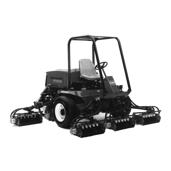
Toro REELMASTER 6700-D Operator's Manual
Traction unit
Hide thumbs
Also See for REELMASTER 6700-D:
- Operator's manual (56 pages) ,
- Service manual (366 pages) ,
- Quick service reference (258 pages)

Related Manuals for Toro REELMASTER 6700-D


Summary of Contents for Toro REELMASTER 6700-D
-
Page 1: Identification & Ordering
FORM NO. 3318-403 GB Rev A OPERATOR’S 0001 MODEL NO. 03802—5 & UP MANUAL MODEL NO. 03802TE—7 0001 & UP ® ® REELMASTER 6700-D TRACTION UNIT © The TORO Company 1995... -
Page 2: Table Of Contents
To order replacement parts from an authorized TORO Distributor, supply the following information: 1. Model and serial numbers. 2. Part number, description, and quantity of parts desired. -
Page 3: Safety Instructions
Safety Training • Store fuel in containers specifically designed for this purpose. Read the instructions carefully. Be familiar with • Refuel outdoors only and do not smoke while the controls and the proper use of the equipment. refueling. • Add fuel before starting the engine. Never Never allow children or people unfamiliar with remove the cap of the fuel tank or add petrol these instructions to use the lawn mower. - Page 4 • before clearing blockages; • never mow across the face of the slope, unless the lawn mower is designed for this • before checking, cleaning or working on the purpose. lawnmower; • after striking a foreign object. Inspect the 6. Use care when pulling loads or using heavy lawnmower for damage and make repairs equipment.
- Page 5 Sound & Vibration Levels Sound Levels This unit has an equivalent continuous A-weighted sound pressure at the operator ear of: 82.5 dB(A), based on measurements of identical machines per 84/538/EEC. Vibration Levels This unit has a vibration level of 2.5 m/s at the posterior, based on measurements of identical machines per ISO 2631 procedures.
-
Page 6: Symbol Glossary
Symbol Glossary Caustic liquids, Poisonous Electrical shock, High pressure High pressure High pressure Crushing of Crushing of chemical burns to fumes or toxic electrocution fluid, injection spray, erosion of spray, erosion of fingers or hand, toes or foot, force fingers or hand gases, asphyxiation into body flesh... - Page 7 Eye protection Head protection Hearing Caution, toxic First aid Flush with water Engine Transmission must be worn must be worn protection must risk be worn Hydraulic Brake system Coolant (water) Intake air Exhaust gas Pressure Fire, open light system & smoking prohibited Level Liquid level...
- Page 8 Engine coolant Engine coolant f Engine Engine intake/ Engine intake/ Engine intake/ Engine start Engine stop pressure ilter lubricating oil combustion air combustion air air filter pressure pressure n/min Engine failure/ Engine rotational Choke Primer (start aid) Electrical preheat Transmission oil Transmission oil Transmission oil malfunction speed/frequency...
-
Page 9: Specifications
Diagnostics; The Automatic Control Electronics, ACET system allows precise timing and control of Toro 4-MaticR 4-Wheel Drive System only: Rear machine functions for maximum reliability. Toro stan- drive axle coupled to hydrostatic transmission via an dard diagnostic display connects to an electronic con-... -
Page 10: Before Operating
Before Operating CAUTION Before servicing or making adjustments to the machine, stop the engine and remove the key from the switch. CHECK THE ENGINE OIL (Fig. 2 & 3) Crankcase capacity is 5 l with filter. Park the machine on a level surface. Release the hood latch and open the hood. -
Page 11: Fill The Fuel Tank
If coolant is low, remove the degasser tank cap and add a 50/50 mixture of water and Peugeot-recommended anti- freeze (Toro Part No. 93-7213). DO NOT USE WATER ONLY OR ALCOHOL/METHANOL BASE COOLANTS. Install the degasser tank cap. Close the hood and secure the latch. - Page 12 Note: A red dye additive for the hydraulic system fluid is available in 20 ml bottles. One bottle is sufficient for 15–23 l. of hydraulic fluid. Order Part No. 44-2500 from your Authorized Toro Distributor Position the machine on a level surface, lower the cutting units and stop the engine.
-
Page 13: Check The Planetary Gear Drive Oil
CHECK THE PLANETARY GEAR DRIVE OIL (Fig. 7) Check the oil if external leakage is noted. Use high-quality SAE 85W-140 wt. gear lubrication as replacement. System capacity is 47.3 cl. With the machine on a level surface, position the wheel so the check/drain plug is at either three or nine o'clock posi- tion. -
Page 14: Check The Torque Of The Wheel Nuts
CHECK THE TORQUE OF WHEEL NUTS OR BOLTS CAUTION Torque the front wheel nuts to 61–74 kPa and the rear wheel nuts to 115–135 kPa after 1–4 hours of operation and again after 10 hours of operation and every 200 hours thereafter. -
Page 15: Know Your Controls
Controls Traction Pedal (Fig. 9)—Controls forward and reverse opera- tion. Depress the top of the pedal to move forward and bottom to move backward. Ground speed depends on how far the pedal is depressed. For no-load, maximum ground speed, fully depress the pedal while the throttle is in FAST. - Page 16 Water-in-the-fuel Light (Fig. 10)—Warns of water in the fuel system. Low Water Level Light (Fig. 10)—Warns that the coolant water level is low. Height-of-Cut Selector Knob (Fig. 11)—Turning the knob to the appropriate setting informs the electronic controller at what height-of-cut the machine is being operated so desired clip may be obtained.
-
Page 17: Operating Instructions
Figure 14 Seat adjusting lever Seat adjusting knob Operating Instructions CAUTION Before servicing or making adjustments to the machine, stop the engine and remove the key from the switch. STARTING AND STOPPING Sit on the seat; keep your foot off the traction pedal. Assure the parking brake is engaged, the traction pedal is in NEUTRAL, the throttle is in the SLOW position and the ENABLE/ DISABLE switch is in the DISABLE position. -
Page 18: Priming Fuel System
To stop, move all controls to NEUTRAL and set the park- ing brake. Return the throttle to the idle position, turn the key to OFF and remove it from the switch. PRIMING THE FUEL SYSTEM (Fig. 15 & 16 IMPORTANT: The fuel system may need to be primed when a new engine is started for the first time, if it runs out of fuel or if maintenance is performed on the fuel sys- tem. -
Page 19: Selecting Clip Rate (Reel Speed)
The approximate ranges of traction speed which will result in the desired clip are as follows for several of the possible heights of cut: SAMPLES OF TRACTION SPEED RANGES FOR VARIOUS HEIGHTS OF CUT Minimum Traction Maximum Traction No. of Blades Height of Cut per C.U. -
Page 20: Clip Rate Selection Chart
grass removed and slightly less clip visibility, move the height-of-cut selector one position lower than specified. Full Speed—There may be times when it is desirable for the reels to run at full speed regardless of the machine’s traction speed. Examples of this are vertical cutting or heavy scalping. In such cases, the height-of-cut selector knob may be set to position "A"... -
Page 21: Reel Control Light
Toro Distributor. PUSHING OR TOWING THE MACHINE In an emergency, the Reelmaster 6700-D can be moved by actu- ating the by-pass valve in the variable displacement hydraulic pump and pushing or towing the machine. -
Page 22: Diagnostic Light
DIAGNOSTIC LIGHT (Fig. 19) The RM 6700-D is equipped with two diagnostic lights which indicate whether or not the electronic controllers are function- ing correctly. The diagnostic light for the main (#1 controller is located on the steering tower panel. When the #1 electronic controller is functioning correctly and the key switch is moved to the ON position, the (#1) controller diagnostic light will be illuminated for approximately 6 seconds. -
Page 23: Checking Interlock Switches
CHECKING THE INTERLOCK SWITCHES The purpose of the interlock switches is to prevent the engine from cranking or starting unless the traction pedal is in NEU- TRAL, the Enable/Disable switch is in DISABLE and the Lower Mow/Raise control is in the neutral position. In addition, the engine will stop when the traction pedal is depressed with the operator off the seat. -
Page 24: Hydraulic Solenoid Valve Functions
ECU problem. If this decal #2 must be used on connection #2. occurs, contact your Toro Distributor for assistance. Turn the key switch to the ON position, but do IMPORTANT: The Diagnostic ACE display must not not start the machine. -
Page 25: Height-Of-Cut Selection Potentiometer
2 or 3 settings different from the desired setting.) This calibration must be done by your Toro distributor. OPERATING CHARACTERISTICS Familiarization—Before mowing grass, practice oper- ating the machine in an open area. Start and stop the engine. - Page 26 WARNING: When operating the machine, always use the seat belt and roll-over protection system together. Warning System—If a warning light comes on during opera- tion, stop the machine immediately and correct the problem before continuing. Serious damage could occur if the machine is operated with a malfunction.
-
Page 27: Maintenance
Radiator& screen for debris 19. Touch-up damaged paint Unusual engine noises Unusual operating noises 10. Hydraulic system oil level Reelmaster 6700-D, 4-Wheel Drive Quick Reference Aid Check/Service (daily) Check/Service (See 1. Oil level, engine Operator’s Manual) 2. Oil level, hydraulic tank 9. - Page 28 Minimum Recommended Maintenance Intervals Maintenance Procedure Maintenance Interval & Service Lube all grease fittings Every Every Every Every 50 Every 100 Inspect the air filter, dust 400 hours 200 hours 800 hours hours hours cup and baffle Check battery level and con nections Change the engine oil filter Inspect cooling system hoses...
- Page 29 GREASING BEARINGS AND BUSHINGS (Fig. 22–30) The machine has grease fittings that must be lubricated regularly with No. 2 General Purpose Lithium Base Grease. If the machine is operated under normal condi- tions, lubricate all bearings and bushings after every 50 hours of operation or immediately after every washing.
- Page 30 Figure 29 Figure 28 Figure 30...
- Page 31 CAUTION Before servicing or making adjustments to the machine, stop the engine and remove the key from the switch. GENERAL AIR CLEANER MAINTE- NANCE Check the air cleaner body for damage which could possi- bly cause an air leak. Replace a damaged air cleaner body. Figure 31 Service the air cleaner filters whenever the air cleaner indi- Air cleaner indicator...
- Page 32 Compressed Air Method A. Blow compressed air from the inside to the outside of the dry filter element. Do not exceed 689 kPa to prevent damage to the element. B. Keep the air hose nozzle at least 5 cm from the filter and move the nozzle up and down while rotating the filter element.
- Page 33 the fuel system becomes contaminated or if the machine is to be stored for an extended period. Use clean fuel to flush out the tank. Fuel Lines and Connections Check lines and connections every 400 hours or yearly, whichever comes first. Inspect for deterioration, damage, or loose connections.
- Page 34 ENGINE COOLING SYSTEM (Fig. 39–40) Removing Debris—Remove debris from the rear screen, oil cooler and radiator daily. Clean more frequently in dirty conditions. IMPORTANT: Never spray water onto a hot engine as damage to the engine may occur. A. Turn the engine off, release the hood latch and raise the hood.
- Page 35 Change hydraulic fluid after every 800 operating hours, in nor- mal conditions. If the fluid becomes contaminated, contact your local TORO distributor because the system must be flushed. Contaminated fluid looks milky or black when compared to clean the oil.
- Page 36 hydraulic fluid. Assure the filter mounting area is clean. Screw the filter on until gasket contacts mounting plate. Then tighten the filter one-half turn. Start the engine and let it run for about two minutes to purge air from the system. Stop the engine and check for leaks.
- Page 37 ADJUSTING THE CUTTING UNIT LIFT RATE (Fig. 45) The cutting unit lift circuit is equipped with an adjustable valve to ensure the front cutting units raise and lower evenly. Adjust the cutting units as follows: Locate the valve under the seat. Loosen the setscrew on the valve.
- Page 38 Place the drain pan under the brake hub on other side of the wheel. Remove the plug from the bottom of the hub and allow the oil to drain. When all oil has drained, re-install the plug in the hub. Add high-quality SAE 85W-140 wt.
- Page 39 Note: Backlapping speed may be increased by moving the height-of-cut selection knob toward to “A”. Each position will increase speed 60 rpm. After changing selector, wait 30 seconds for the system to respond to the new speed tar- get. Make initial reel-to-bedknife adjustments appropriate for backlapping on all cutting units that are to be backlapped.
-
Page 40: Preparation For Seasonal Storage
Coat the cable terminals and battery posts with Grafo 112X skin-over grease (Toro Part 10. Check anti freeze protection and add a 50/50 No. 505-47) or petroleum jelly to prevent solution of water and Peugeot recommended anti corrosion.