Crestron DM-NVX-350 Product Manual
Network av encoders/decoders
Hide thumbs
Also See for DM-NVX-350:
- Product manual (36 pages) ,
- Quick start manual (9 pages) ,
- Do manual (2 pages)

Related Manuals for Crestron DM-NVX-350


Summary of Contents for Crestron DM-NVX-350
- Page 1 DM NVX® Network AV Encoders/Decoders DM-NVX-350 DM-NVX-351 DM-NVX-352 DM-NVX-350C DM-NVX-351C DM-NVX-352C Product Manual Crestron Electronics, Inc.
- Page 2 Crestron disclaims any proprietary interest in the marks and names of others. Crestron is not responsible for errors in typography or photography.
-
Page 3: Table Of Contents
Contents Introduction ............................ 1 Physical Description ........................2 DM-NVX-350, DM-NVX-351, and DM-NVX-352 .................. 2 Front Panel, DM-NVX-350 and DM-NVX-351 ................2 Front Panel, DM-NVX-352 ......................... 4 Rear Panel ............................. 5 DM-NVX-350C and DM-NVX-351C ......................7 DM-NVX-352C ............................8 Status and Configuration ......................10 DMF-CI-8 Chassis Details ........................ - Page 4 Using the Web Interface ........................64 Using SIMPL Windows ........................67 Network Port Selection........................... 69 Device Mode Locking ..........................70 Crestron XiO Cloud Service Connection ..................... 71 Test Pattern Generator .......................... 72 Using the Web Interface ........................72 Using SIMPL Windows ........................75 Interoperability with DM NVX 4K60 4:2:0 and 1080p Encoders and Decoders ......
- Page 5 IGMP Snooping ........................... 83 Troubleshooting .......................... 86 Appendix. Device Discovery ...................... 89 Product Manual – DOC. 7839M Contents • iii...
-
Page 7: Introduction
• IGMP snooping • Troubleshooting • In addition, information about device discovery of a DM NVX device using Crestron Toolbox™ software is provided in the appendix of this manual. For DM-NVX-35x(C) installation information, refer to the following documents as applicable: DM-NVX-350, DM-NVX-351, and DM-NVX-352 Quick Start (Doc. -
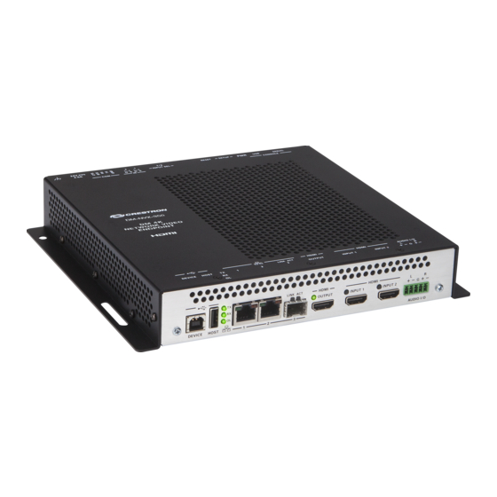
Page 8: Physical Description
The following sections provide information about the connectors, controls, and indicators that are available on DM-NVX-35x(C) devices. DM-NVX-350, DM-NVX-351, and DM-NVX-352 This section provides information about the front and rear panels of the DM-NVX-350, DM-NVX-351, and DM-NVX-352. Front Panel, DM-NVX-350 and DM-NVX-351 The following illustration shows the front panel of the DM-NVX-350 and DM-NVX-351. - Page 9 LAN connection, the port requires connection to a 1000BASE-T switch in order to stream network video. The DM-NVX-350 and DM-NVX-351 can be powered by the connection of LAN 1 to a UPOE compliant Ethernet switch, a Crestron DM-PSU-ULTRA-MIDSPAN, or other Crestron approved power injector (sold separately).
-
Page 10: Front Panel, Dm-Nvx-352
The DM-NVX-352 can be powered by the connection of LAN 1 to a UPOE compliant Ethernet switch, a Crestron DM-PSU-ULTRA-MIDSPAN, or other Crestron approved power injector (sold separately). For additional information, refer to Answer ID 5791 in the Online Help section of the Crestron website (www.crestron.com/onlinehelp). The DM-NVX-352 can also be powered using the included power pack. -
Page 11: Rear Panel
HDMI connections require an appropriate adapter or interface cable to accommodate a DVI or Dual-Mode DisplayPort signal. CBL-HD-DVI interface cables are sold separately. Device control via CEC requires the use of a Crestron 3-Series® or later control system. Product Manual – DOC. 7839M... - Page 12 24 VDC power input; Power pack included Ground: 6-32 screw, chassis ground lug ∗ Device control via IR and RS-232 requires integration with a Crestron 3-Series or later control system. 6 • DM-NVX-35x(C) Encoders/Decoders Product Manual – DOC. 7839M...
-
Page 13: Dm-Nvx-350C And Dm-Nvx-351C
LAN 3 can be used as the primary LAN connection or can be connected to another DM NVX device. LAN 3 can connect to a fiber-optic network using the appropriate Crestron SFP-1G transceiver module (sold separately). Refer to the SFP-1G Series Installation Guide (Doc. 7979) for information about installing Crestron SFP-1G Series transceiver modules. -
Page 14: Dm-Nvx-352C
HDMI connections require an appropriate adapter or interface cable to accommodate a DVI or Dual-Mode DisplayPort signal. CBL-HD-DVI interface cables are sold separately. Device control via CEC requires integration with a Crestron 3-Series or later control system. The DEVICE and HOST ports cannot be used simultaneously. - Page 15 LAN connection requires connection to a 1000BASE-T switch in order to stream network video. LAN 2 can connect to a fiber-optic network using the appropriate Crestron SFP-1G transceiver module (sold separately). Refer to the SFP-1G Series Installation Guide (Doc. 7979) for information about installing Crestron SFP-1G Series transceiver modules.
-
Page 16: Status And Configuration
Status and Configuration This section provides information about viewing or configuring the following items using the web interface or SIMPL Windows as applicable: DMF-CI-8 chassis details • DM NVX Director® virtual switching appliance • Encoding and decoding functionality • Automatic point-to-point connectivity •... -
Page 17: Dmf-Ci-8 Chassis Details
Crestron XiO Cloud service connection • Test pattern generator • Interoperability with DM NVX 4K60 4:2:0 and 1080p Encoders and Decoders • Enterprise-grade security • Automatic firmware update • DMF-CI-8 Chassis Details NOTE: DMF-CI-8 chassis details apply to the DM NVX cards only and do not apply to DM NVX surface-mountable endpoints. -
Page 18: Using Simpl Windows
Using SIMPL Windows Using the top-level programming slot for the DM NVX card, program the <ChassisSerialNumber_F> serial output join to report the serial number of the chassis in which the card is installed. Program the <CardSlotInfo_F> serial output join to report the slot number in which the card is installed in the chassis. -
Page 19: Encoding And Decoding Functionality
Encoding and Decoding Functionality A DM-NVX-35x(C) device can be configured to function as a network AV encoder (transmitter) or decoder (receiver): As an encoder, a DM NVX device allows a laptop computer, camera, or other • media source to be connected via an HDMI cable and then transmitted over the network. -
Page 20: Using Simpl Windows
Settings Tab – Stream, Mode Configuration When a different mode is selected, a prompt appears asking for confirmation that the device be rebooted. Click Yes to reboot the device. Device Reboot Prompt For additional information, refer to the online help of the web interface. Using SIMPL Windows Using the top-level programming slot for the DM-NVX-35x(C) device, set the <DeviceMode>... -
Page 21: Using The Web Interface
When point-to-point mode is enabled, no additional configuration is required for the encoder or decoder to operate in point-to-point mode; however, the operating mode of a DM-NVX-35x(C) device must be set correctly. If the device is to function as an encoder, the operating mode must be set to Transmitter. -
Page 22: Stream Statistics
Stream Statistics Statistics can be displayed to indicate the number of packets received or transmitted, the number of dropped packets, and the bit rate of the received stream. To enable or disable or to reset stream statistics, use the web interface or SIMPL Windows as discussed in the following sections. -
Page 23: Image Preview
Images can be previewed in the DM NVX web interface and accessed remotely using a web browser. The images can also be previewed on a Crestron touch screen or third-party interface. -
Page 24: Using Simpl Windows
<ip address> is the IP address of the DM NVX device. • <filename> is the file name of the image preview file. • For example: https://admin:admin@172.30.160.90/preview/preview_540px.jpeg admin is the user name used to access the DM NVX web server • admin is the password used to access the DM NVX web server •... -
Page 25: Multicast Ttl (Time-To-Live)
Multicast TTL (Time-to-Live) NOTE: Multicast TTL configuration applies to a DM-NVX-35x(C) device that is operating as a transmitter. Multicast TTL provides the ability to limit or extend the hop limit of a DM NVX stream that traverses routers. In IPv4 multicasting, routers have a TTL threshold assigned to each interface. -
Page 26: Using Simpl Windows
Settings Tab – Stream, Multicast TTL Configuration Using SIMPL Windows Configure multicast TTL as follows: Using the top-level programming slot: a. Trigger the <AutomaticInitiationDisabled> digital input join. b. Trigger the <Stop> digital input join. 2. In Slot-01: Stream Transmit, set the <MulticastTTL> analog input join to the desired value (1 to 255). -
Page 27: Dscp (Differentiated Services Code Point)
DSCP (Differentiated Services Code Point) NOTE: DSCP applies to a DM-NVX-35x(C) device that is operating as a transmitter. To implement Quality of Service (QoS), IP networks use the DSCP value. Within an IP packet header, the DSCP defines a value from 0 to 63 that maps to a certain traffic classification. -
Page 28: Automatic Routing Of Video Inputs
Settings Tab – Stream, Custom DSCP Automatic Routing of Video Inputs Automatic routing between video inputs can be enabled or disabled. When automatic routing is enabled, the device automatically routes the last connected input. To configure automatic routing, use the web interface or SIMPL Windows as discussed in the following sections. -
Page 29: Using Simpl Windows
Settings Tab – Routing, Automatic Input Routing Using SIMPL Windows Using the top-level programming slot for the DM NVX device, trigger the <AutomaticRoutingEnabled> digital input join to enable automatic routing. To disable automatic routing, trigger the <AutomaticRoutingDisabled> digital input join. For additional information, refer to the SIMPL Windows help file. -
Page 30: Automatic Display Control
Automatic Display Control For the DM-NVX-350, DM-NVX-351, and DM-NVX-352, the display device can be turned on or off automatically via RS-232, IR, or CEC (Consumer Electronics Control). For the DM-NVX-350C, DM-NVX-351C, and DM-NVX-352C, CEC can be used to automatically turn a display device on or off. - Page 31 8. Do one of the following: If CEC is selected in step 4, enter the CEC command in the Power Off (No • Sync Detected) and Power On (Sync Detected) sections. If a custom command is desired, enter the desired command, and then select the desired terminator and format.
- Page 32 Settings Tab – Outputs, Automatic Display Power (Shown with DM NVX Device in Receiver Mode and CEC Interface Command Selected) 26 • DM-NVX-35x(C) Encoders/Decoders Product Manual – DOC. 7839M...
-
Page 33: Video Wall Processing
Video Wall Processing NOTE: Video wall processing applies to DM-NVX-35x(C) devices that function as receivers. Multiple DM-NVX-35x(C) receivers can be combined to configure a video wall composed of up to 64 individual displays (up to eight columns of displays by eight rows of displays). A separate DM-NVX-35x(C) device is required for each display. - Page 34 Settings Tab – Outputs, Video Wall Configuration 28 • DM-NVX-35x(C) Encoders/Decoders Product Manual – DOC. 7839M...
-
Page 35: Using Simpl Windows
Using SIMPL Windows Configure a video wall in Slot-06: HDMI OUT: Set the <VideoWallMode>, <Horizontal_Bezel_Compensation>, and <Vertical_Bezel_Compensation> analog input joins to the desired values. 2. Repeat step 1 for each DM-NVX-35x(C) receiver that connects to a display for inclusion in the video wall. For additional information, refer to the SIMPL Windows help file. -
Page 36: Using Simpl Windows
Settings Tab – Outputs, Underscan Configuration Using SIMPL Windows Adjust underscan in Slot-06: HDMI Out. Set the <Underscan> analog input join to the desired value. For additional information, refer to the SIMPL Windows help file. 30 • DM-NVX-35x(C) Encoders/Decoders Product Manual – DOC. 7839M... -
Page 37: User-Selectable Output Resolution
User-Selectable Output Resolution NOTE: User-selectable output resolution applies to a DM-NVX-35x(C) device that functions as a receiver. To select the desired output resolution, use the web interface or SIMPL Windows as discussed in the following sections. Using the Web Interface To configure the output resolution: Click the Settings tab and then click Outputs. -
Page 38: Using Simpl Windows
Settings Tab – Outputs, HDMI Output Resolution Configuration Using SIMPL Windows Configure the output resolution in Slot-06: HDMI Out. Set the <Resolution> analog input join to the desired value. For additional information, refer to the SIMPL Windows help file. 32 • DM-NVX-35x(C) Encoders/Decoders Product Manual –... -
Page 39: Maximum Color Depth And Color Space Mode
Maximum Color Depth and Color Space Mode Configure the maximum color depth (maximum bit depth supported by the output) and HDMI color space mode using the web interface or SIMPL Windows. Using the Web Interface To configure maximum color depth and color space mode: Click the Settings tab and then click Outputs. - Page 40 Settings Tab – Outputs, HDMI Output Maximum Color Depth and Color Space Mode 34 • DM-NVX-35x(C) Encoders/Decoders Product Manual – DOC. 7839M...
-
Page 41: Using Simpl Windows
Using SIMPL Windows Configure maximum color depth and color space mode in Slot-06: HDMI Out. Set the <MaximumColorDepth> analog input join to the appropriate value for the maximum bit depth supported by the output. Set the <ColorSpaceMode> analog input join to the desired value for the HDMI color space. - Page 42 c. In the Aspect Ratio Mode drop-down list, select the desired setting: Maintain Aspect Ratio: (Default setting) Maintains the aspect ratio of • the image. Stretch: Stretches the image to fill the screen in both the horizontal and • vertical directions. The aspect ratio of the image is not maintained. 1:1: Sets a 1x1 pixel image.
- Page 43 6. If the image is to be retrieved from a remote server: a. In the Remote Path text entry box, enter the URL (HTTP, HTTPS, or FTP) to access the image file from a remote server. The image is uploaded and appears in the Preview window.
- Page 44 Settings Tab, Outputs, Background Image 38 • DM-NVX-35x(C) Encoders/Decoders Product Manual – DOC. 7839M...
- Page 45 Settings Tab, Outputs, Background Image Retrieval from Local Device, Adding an Image Settings Tab, Outputs, Background Image Retrieval from Local Device Product Manual – DOC. 7839M DM-NVX-35x(C) Encoders/Decoders • 39...
-
Page 46: Using Simpl Windows
Settings Tab, Outputs, Background Image Retrieval from Remote Server Using SIMPL Windows Enable or disable background image functionality in Slot-06-05: Background Image. Trigger the <Enable> digital input join to enable background image functionality. To disable background image functionality, trigger the <Disable> digital input join. For additional information, refer to the SIMPL Windows help file. -
Page 47: Edid (Extended Display Identification Data)
EDID (Extended Display Identification Data) EDID configuration enables management of the EDID that is to be sent to the upstream device connected to an HDMI input of a DM NVX device. If an EDID other than the default EDID is desired, use the web interface to configure the EDID. To view a list of default or user EDID files, search for an EDID file, or add or delete user EDID files, go to the Action menu in the upper-right corner of the web interface and select EDID Management. - Page 48 To select an EDID for the inputs: Click the Settings tab and then click Inputs. 2. Do either of the following: In the Global EDID section, set a global EDID for all inputs. • In the Inputs section, set the desired EDID for Input 1 and Input 2 by clicking •...
- Page 49 Settings Tab – Inputs, EDID Configuration Product Manual – DOC. 7839M DM-NVX-35x(C) Encoders/Decoders • 43...
-
Page 50: Fixed, Adaptive, Or Variable Bit Rate
Fixed, Adaptive, or Variable Bit Rate NOTES: Configuration of a fixed, adaptive, or variable bit rate setting is applicable to a • DM-NVX-35x(C) device that functions as a transmitter. A nonblocking network is required for DM NVX devices. • The bit rate of a stream can be set to fixed, adaptive, or variable: A fixed bit rate, also referred to as Constant Bit Rate (CBR), is user specified and •... -
Page 51: Using The Web Interface
Using the Web Interface For a DM NVX device that is set to Transmitter mode, set the bit rate of the stream: Click the Settings tab and then click Stream. 2. In the Advanced section, select the bit rate type in the Bitrate Type drop-down list: Fixed, Adaptive, or Variable. -
Page 52: Subscriptions
Subscriptions NOTE: Subscription configuration applies to a DM-NVX-35x(C) device that functions as a receiver. Subscription of a DM NVX transmitter to a DM NVX receiver sets up Real Time Streaming Protocol (RTSP) negotiation between the DM NVX receiver and the DM NVX transmitter. - Page 53 Settings Tab – Subscriptions 3. Under the Settings tab, click Routing. In the Stream Routing section, select the desired transmitter to be routed to the receiver. Settings Tab – Routing, Stream Routing For additional information, refer to the online help of the web interface. Product Manual –...
-
Page 54: Using Simpl Windows
SIMPL Windows help file. Daisy Chain DM-NVX-350(C) and DM-NVX-351(C) devices include three LAN ports (two RJ-45 LAN ports and one SFP LAN port). A DM-NVX-352(C) device includes two LAN ports (one RJ-45 LAN port and one SFP LAN port). The LAN ports can be used to daisy chain multiple DM NVX devices. -
Page 55: Switching Nonsubscribed Transmitters
Using SIMPL Windows Switch subscribed transmitters in Slot-1000: XIO Routing: For each receiver in the daisy chain, clear the existing route by setting the <VideoOut> analog input join to 0. Using SIMPL Windows, all routes for all receivers in the chain can be cleared at one time. 2. -
Page 56: 7.1 Surround Sound Audio
DM NAX audio over IP supports the AES67 standard. AES67 support allows the selected audio source to be transmitted as a 2-channel AES67 source while another 2-channel AES67 audio stream is received from a Crestron DSP or other third-party device and combined with the video signal. When the DM-NVX-35x(C) device functions as a transmitter, the received AES67 audio stream can be output via the local HDMI output, primary AV stream, and analog audio output. -
Page 57: Using The Web Interface
Using the Web Interface Configure DM NAX (AES67) audio by clicking the Settings tab and then configuring DM NAX (AES67) audio and routing: The DM NAX (AES67) Audio section varies depending on whether the DM NVX • endpoint is in Transmitter or Receiver mode. Refer to the “Configuring DM NAX (AES67) Audio for a DM NVX Transmitter”... - Page 58 Settings Tab - DM NAX (AES67) Audio Configuration in Transmitter Mode For additional information, refer to the online help of the web interface. 52 • DM-NVX-35x(C) Encoders/Decoders Product Manual – DOC. 7839M...
- Page 59 Configuring DM NAX (AES67) Audio for a DM NVX Receiver In the DM NAX (AES67) Audio section under the Settings tab, In the DM NAX (AES67) Transmit section, enter the multicast address and port • number. In the DM NAX (AES67) Transmit Advanced section, set the Auto Initiation toggle •...
- Page 60 Settings Tab - DM NAX (AES67) Audio Configuration in Receiver Mode 54 • DM-NVX-35x(C) Encoders/Decoders Product Manual – DOC. 7839M...
-
Page 61: Using Simpl Windows
Configuring DM NAX (AES67) Audio Routing To configure DM NAX (AES67) audio routing: Click the Settings tab and then clicking Routing. 2. In the Input Routing section: a. Set Audio Source to DM NAX (AES-67) Audio. b. Set Analog Audio Mode to Insert or Extract. c. -
Page 62: Dante Or Aes67 Audio Embedding And De-Embedding
Dante and AES67 support enables the selected audio source to be transmitted as a 2-channel Dante or AES67 source while another 2-channel Dante or AES67 audio stream is received from a Crestron DSP or other third-party device and combined with the video signal. -
Page 63: Using The Web Interface
Using the Web Interface Configure Dante or AES67 audio by clicking the Settings tab and then configuring stream and routing settings: In the Stream section, fill in the appropriate information in the Dante/Aes-67Name text box by entering the name of the Dante module that will be used in the Dante Controller. -
Page 64: Using Simpl Windows
2. In the Routing section: a. Set Audio Source to Dante/AES-67 Audio. b. Set Analog Audio Mode to Insert or Extract. c. Set Dante/AES-67 Transmit Audio Source to the desired audio source for the Dante or AES67 output. Settings Tab – Routing, Dante or AES67 Configuration For additional information, refer to the online help of the web interface. -
Page 65: Analog Audio Input Or Output
HDMI inputs. NOTE: Analog audio output from a DM-NVX-350, DM-NVX-350C, DM-NVX-352, or DM-NVX-352C is functional only when the device is receiving a 2-channel stereo input signal. The DM-NVX-351 and DM-NVX-351C can derive a 2-channel downmix signal from a multichannel surround sound source. - Page 66 b. (Applicable only when Audio Mode is set to Insert) Set Audio Source to Analog Audio. Settings Tab – Routing, Analog Audio Source Configuration 2. (Applicable only if Analog Audio Mode is set to Extract) Under the Settings tab: a. Click Outputs and then click the Edit button. b.
- Page 67 Settings Tab – Outputs, Analog Audio Volume Configuration For additional information, refer to the online help of the web interface. Product Manual – DOC. 7839M DM-NVX-35x(C) Encoders/Decoders • 61...
-
Page 68: Using Simpl Windows
Using SIMPL Windows NOTE: To insert or extract analog audio, use the web interface. Using the top-level programming slot for the DM NVX device, set the <AudioSource> analog input join to Analog Audio if analog audio is to be inserted into a network video stream or the HDMI output. -
Page 69: Using Simpl Windows
Settings Tab – Routing, Breakaway Audio Configuration Using SIMPL Windows Using the top-level programming slot for the DM NVX device, set the <AudioSource> analog input join to one of the following: Input 1 • Input 2 • Analog Audio • Primary Stream Audio •... -
Page 70: Usb 2.0 Routing
USB peripheral devices are supported, including whiteboards, touch screens, game controllers, web cameras, mobile devices, headsets, and flash drives. Crestron does not guarantee that all USB products are compatible with DM NVX devices. For USB 2.0 Layer 2 transport, one local (DEVICE port) connection supports up to seven remote (HOST port) connections simultaneously. - Page 71 3. In the USB Mode drop-down list, select Local for the local extender or Remote for a remote extender. 4. In the Transport Mode drop-down list, select either of the following: Layer 2: Enables Layer 2 transport of USB 2.0 data. This mode is compatible •...
- Page 72 8. (Applicable to Remote USB mode only) Do either of the following: In the Remote Device ID text box for Layer 2 transport, enter the MAC • address of the local extender. In the Remote Device ID text box for Layer 3 transport, enter the IP address •...
-
Page 73: Using Simpl Windows
Using SIMPL Windows Using SIMPL Windows, configure USB routing in Slot 30: USB: Determine the DM-NVX-35x(C) devices that are to be paired: One DM NVX device functions as the local extender (LEX); that is, the • DEVICE port connects to a computer or other host device. For Layer 2 transport, up to seven DM NVX devices can function as remote •... - Page 74 On the LEX device, the <UsbRemoteDeviceId_F> and <UsbRemoteDeviceId2_F> through <UsbRemoteDeviceId7_F> serial output joins report the MAC address of each REX device to which the LEX device is to be paired. For Layer 3 transport: • a. Copy the IP address (UsbLocalDeviceIpAddress) of the LEX device into the <UsbRemoteDeviceIpAddress>...
-
Page 75: Network Port Selection
3. If Port Selection is set to On, assign each of the following traffic types to a specific Ethernet port: NOTE: For the DM-NVX-350(C) and DM-NVX-351(C), Ethernet ports 1, 2, and 3 are available for use. For the DM-NVX-352(C), Ethernet ports 1 and 2 are available for use. -
Page 76: Device Mode Locking
Settings Tab, Port Selection Device Mode Locking Device mode locking controls whether the SETUP button on a DM-NVX-35x and the DMF-CI-8 front panel can be used to change the operating mode of the DM-NVX-35x and DM-NVX-35xC devices, respectively. The operating mode determines when the DM-NVX-35x(C) device functions as a receiver or transmitter. -
Page 77: Crestron Xio Cloud Service Connection
For additional information, refer to the online help of the web interface. Crestron XiO Cloud Service Connection The Crestron XiO Cloud® service allows supported Crestron devices across an enterprise to be managed and configured from one central and secure location in the cloud. -
Page 78: Test Pattern Generator
Test Pattern Generator NOTE: Test pattern generator applies to a DM-NVX-35x(C) device that functions as a transmitter. The built-in test pattern generator can be used during setup to ensure that video streaming is functional and can also be used as a tool for the adjustment, calibration, and alignment of displays, projectors, and video walls. - Page 79 In the Test Pattern Generator section, do the following: In the Test Pattern drop-down list, select the desired test pattern. Available options are listed in the following table. TEST PATTERN OPTION TEST PATTERN Off (default setting) Disables the test pattern generator SMPTE ColorBars Black White...
- Page 80 Vertical Lines Grid Color Bars Gray Gradient 74 • DM-NVX-35x(C) Encoders/Decoders Product Manual – DOC. 7839M...
-
Page 81: Using Simpl Windows
RGB Gradient Frequency Adjust 2. In the Resolution drop-down list, select the desired resolution of the test pattern. Available options are the following: 3840x2160p60 RGB 8-bit 3840x2160p60 Y420 8-bit 3840x2160p30 RGB 8-bit 1920x1080p60 RGB 8-bit 720p60 RGB 8-bit Using SIMPL Windows Configure the test pattern generator in Slot-12: Test Pattern Generator. -
Page 82: Interoperability With Dm Nvx 4K60 4:2:0 And 1080P Encoders And Decoders
Interoperability with DM NVX 4K60 4:2:0 and 1080p Encoders and Decoders DM-NVX-35x(C) devices are interoperable with DM NVX 4K60 4:2:0 Series and 1080p Series encoders and decoders. The following table lists the 4K60 4:2:0 and 1080p encoders and decoders based on functionality. DM NVX 4K60 4:2:0 and 1080p Encoders and Decoders FUNCTIONALITY DM NVX 4K60 4:2:0 SERIES... -
Page 83: Using Simpl Windows
Settings Tab – Stream, Stream Type Using SIMPL Windows In Slot-01: Stream Transmit, set the <StreamType> analog input join to the desired stream type (Pixel Perfect Processing [Default] or DM-NVX-D10/D20 Series). For additional information, refer to the SIMPL Windows help file. Enterprise-Grade Security DM NVX devices incorporate advanced security features such as user and group authentication management, IEEE 802.1X authentication, AES-128 content encryption,... - Page 84 Security Tab – Authentication Management of Users and Groups 78 • DM-NVX-35x(C) Encoders/Decoders Product Manual – DOC. 7839M...
-
Page 85: Ieee 802.1X Authentication
IEEE 802.1X Authentication IEEE 802.1X is a network standard designed to enhance the security of wireless and wired LANs. The standard defines how to provide authentication for devices trying to connect to other devices on the LAN. To manage trusted certificate authorities, go to the Action menu in the upper-right corner of the web interface and select Manage Certificates. - Page 86 To configure IEEE 802.1X authentication in the web interface, click the 802.1X Configuration tab. For detailed information, refer to the online help of the web interface. 802.1X Authentication Tab 80 • DM-NVX-35x(C) Encoders/Decoders Product Manual – DOC. 7839M...
-
Page 87: Automatic Firmware Update
A DM NXV device can be automatically updated with the latest firmware at scheduled intervals. To configure automatic firmware update: Using the Crestron Auto Update Tool, generate a manifest file (*. mft). The file is placed on an FTP (File Transfer Protocol) or SFTP (Secure File Transfer Protocol) server. - Page 88 Clicking Update Now causes the firmware to be updated at the current time; however, the schedule that is set in step 2d above remains in effect. Settings Tab – System Setup, Auto Update 82 • DM-NVX-35x(C) Encoders/Decoders Product Manual – DOC. 7839M...
- Page 89 IGMP Snooping A DM NVX device sends IGMP join and leave messages. NOTE: DM NVX devices support IGMPv2 and IGMPv3 only. IGMPv1 is not supported. The IGMP snooping support version (v2 or v3) is configurable in the web interface. The desired version can be selected under the Settings tab in the System Setup – Network Interface section.
- Page 90 NOTES: DM NVX devices do not support random-timer and source-specific queries. • As a host, a DM NVX device configured for support of IGMPv3 is compatible with a • network switch (IGMP querier) that is configured for IGMPv2. IGMP snooping switches build forwarding lists by listening for and, in some cases, intercepting IGMP messages.
- Page 91 If the network switch supports IGMP fast leave, enable the configuration at the • port, global, or VLAN level. If the network switch supports PIM snooping, enable the configuration to prevent • flooding IP multicast traffic toward multicast router (mrouter) ports. Product Manual –...
- Page 92 Troubleshooting The following table provides troubleshooting information. If further assistance is required, contact a Crestron customer service representative. DM NVX Encoder/Decoder Troubleshooting PROBLEM POSSIBLE CAUSE(S) CORRECTIVE ACTION 4K60 4:4:4 2-channel non-HDR or The display device is not Configure the display device properly.
- Page 93 An incorrect audio source is Set the audio source to analog audio. selected. The audio is multichannel Switch the audio input to on a DM-NVX-350 or 2-channel audio. DM-NVX-350C, which do not downmix a 2-channel signal from a multichannel surround sound source.
- Page 94 In the Action menu located in the upper-right corner of the web interface, click • Restore. From the Tools menu in the Crestron Toolbox software, select Text Console and • issue the restore command. Power cycle the device 11 times. After the eleventh power cycle, wait until the •...
- Page 95 The security software running on the computer may send a program alert • regarding the attempt of the Crestron Toolbox software to connect to the network. Allow the connection so that the Device Discovery Tool can be used. The DM NVX device is discovered and is listed in the device list on the left side of the screen.
- Page 96 Crestron Electronics, Inc. Product Manual – DOC. 7839M 15 Volvo Drive, Rockleigh, NJ 07647 Tel: 888.CRESTRON 3/15/2022 Fax: 201.767.7576 Specifications subject to www.crestron.com change without notice.
Need help?
Do you have a question about the DM-NVX-350 and is the answer not in the manual?
Questions and answers