
Related Manuals for Toro 38701


Summary of Contents for Toro 38701
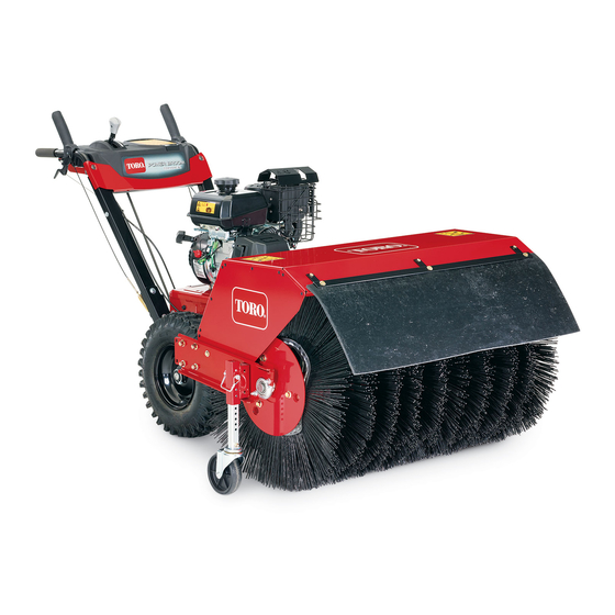
- Page 1 Form No. 3439-892 Rev B Power Broom Model No. 38701—Serial No. 400000000 and Up *3439-892* Register at www.Toro.com. Original Instructions (EN)
- Page 2 Whenever you need service, genuine Toro parts, or additional information, contact an Authorized Service Dealer or Toro Customer Service and have the model and serial numbers of your product ready. Figure 1 identifies the location of the model and serial numbers on the product.
-
Page 3: Table Of Contents
Contents Safety Safety ............... 3 This machine has been designed in accordance with General Safety ........... 3 ANSI/OPEI B71.3 and ANSI B71.4 specifications. Slope Indicator ........... 4 This product is capable of injuring hands and feet and Safety and Instructional Decals ......5 of throwing objects. -
Page 4: Slope Indicator
Slope Indicator g011841 Figure 3 1. The maximum slope you can safely operate the machine on is 10°. Use the slope indicator to determine the degree of slope of hills before operating. Do not operate this machine on a slope greater than 10°. Fold along the appropriate line to match the recommended slope. -
Page 5: Safety And Instructional Decals
Safety and Instructional Decals Safety decals and instructions are easily visible to the operator and are located near any area of potential danger. Replace any decal that is damaged or missing. decal112-9028 112-9028 1. Warning—stay away from moving parts; keep all guards in place. - Page 6 decal135-2867 135-2867 1. Warning-Read the Operator’s Manual. Do Not operate this 4. Warning-Stop engine and remove spark plug before adjusting, machine unless you are trained. Stay away from moving servicing, or cleaning machine and attachments. Before parts; keep all guards in place. leaving the operator’s position, disengage broom, traction drive, and stop engine.
-
Page 7: Product Overview
Product Overview g326826 Figure 5 4. Recoil-start handle 1. Choke control g325102 2. Fuel-shutoff valve 5. Engine On/Off switch Figure 4 3. Throttle control 1. Wheel-clutch lever 6. Traction-drive lever 2. Broom-angle lever 7. Fuel-tank cap 3. Broom-drive lever 8. Broom and hood Fuel-Shutoff Valve 4. -
Page 8: Specifications
(Figure To ensure optimum performance and continued safety To engage the broom, squeeze the lever to the handle. certification of the machine, use only genuine Toro To disengage the broom, release the right lever. replacement parts and accessories. Replacement parts and accessories made by other manufacturers... -
Page 9: Before Operation
Operation Use only clean, fresh (no more than 30 days old), fuel from a reputable source. Fill the fuel tank as shown in Figure 7; do not fill above Before Operation the bottom of the fuel tank neck. Before Operation Safety General Safety •... -
Page 10: Adjusting The Broom Height
Raise or lower the caster wheel tube to adjust the area swept by the broom as stated in Checking the Sweeping Path (page Note: Select any hole combination that is in alignment to place and latch the retaining pin; match the same position on the other side. For finer adjustment, slide the adjuster sleeve 1 pin hole up or down on the caster wheel tube to adjust the broom height in 3 mm (1/8 inch) -
Page 11: Operating The Engine
Operating the Engine • Do not operate the machine near glass enclosures, automobiles, window wells, drop offs, etc. without properly adjusting the broom discharge angle. Positioning the Air-Cleaner Cover • Do not operate the machine without good visibility for Cold or Warm Air Temperature or light. - Page 12 Opening the Fuel-Shutoff Valve Starting the Engine On the right side of the engine, rotate the engine Move the fuel-shutoff valve located below the choke, On/Off switch clockwise to the O position to the right to turn on fuel (Figure 11).
-
Page 13: Driving The Machine
Allow the engine to run for a minimum of 15 seconds, then turn the engine On/Off switch to the O position to stop the engine (Figure 12). Wait for all moving parts to stop before leaving the operating position. Use the fuel-shutoff valve to shut off fuel when you will not use the machine for a few days, park the machine inside a building, or transport the g326524... -
Page 14: Operating The Broom
Pivoting the Machine with the Engine Shutoff Squeeze both wheel-clutch levers simultaneously and pivot the machine (Figure 18). g326522 Figure 17 Note: When you complete the turn, release the wheel-clutch lever. The traction drive engages both wheels. • Momentarily squeeze and release the left or right wheel-clutch lever to make steering adjustments and keep the machine moving in a straight line, especially in deep snow. -
Page 15: Adjusting The Broom Side Angle
WARNING Contact with a rotating broom can result in serious personal injury or death to the operator or bystanders. • To remove an obstruction from the broom; refer to Clearing a Clogged Broom (page 16). • Do not operate the machine if the broom drive lever is not functioning properly. -
Page 16: Using The Alternate Caster Location
Clearing a Clogged Broom • 19° to the left • Straight ahead • WARNING 19° to the right Once the broom is positioned, release the The rotating broom could cause serious broom angle lever. injury. Important: Ensure that the broom locks into Shut off the engine and allow all rotating parts place at one of the 3 positions. -
Page 17: Preventing Freeze-Up After Use
Preventing Freeze-up after • In snowy and cold conditions, some controls and moving parts may freeze. Do not use excessive force when trying to operate frozen controls. If you have difficulty operating any control or part, start the engine and let it run for a few minutes. •... -
Page 18: Maintenance
• Check all fasteners at frequent intervals for proper tightness to ensure that the machine is in safe working condition. • Do not change the governor settings on the engine. • Purchase only genuine Toro replacement parts and accessories. -
Page 19: Lubrication
Remove the belt cover and the engine shield. Move the speed-selector lever to the R2 position. Dip a long, clean, small-tipped paint brush in automotive engine oil and lightly lubricate the hex shaft (Figure 24). Important: Do not get oil on the rubber wheel or the aluminum friction-drive plate as the traction drive will slip (Figure... - Page 20 Secure the air-filter cover to the base with the latches. Checking the Engine-Oil Level Service Interval: Before each use or daily g023795 Engine Oil Type: Toro 4–Cycle Premium Engine Oil Figure 25 Use high-quality detergent oils (including synthetic) 1. Air-filter base 4. Cover of API (American Petroleum Institute) service class 2.
- Page 21 Insert the dipstick into the filler neck and tighten the dipstick by hand. Changing the Engine Oil Service Interval: After the first 5 hours Every 100 hours (more frequently in severe conditions). Oil capacity: 0.60 L (0.63 qt) Note: Drain the engine oil while the engine is warm. Place a pan under drain fitting and remove the oil-drain cap (Figure...
-
Page 22: Fuel System Maintenance
Spark-plug gap: 0.76 mm (0.030 inch) Disconnect the spark-plug wire from the terminal of the spark plug (Figure 22). Clean the area around the base of the spark plug. Remove the spark plug from the cylinder head by rotating the plug counterclockwise. Examine the plug for wear and damage (Figure 30). -
Page 23: Drive System Maintenance
Checking the Traction Cable Adjustment Service Interval: After the first 2 hours—Check the traction cable adjustment and correct it if necessary. Yearly—Check the traction cable adjustment and correct it if necessary. Important: If the machine does not drive in the forward or reverse speeds or it drives when you release the traction lever, adjust the traction cable;... -
Page 24: Broom Maintenance
Adjusting the Traction Cable Loosen the jam nut (Figure 34). g019073 Figure 36 1. Nut 2. Shear pin If the shear pin is damaged, remove the pin, g325108 Figure 34 replace it, and secure the it with a nut. 1. Adjuster tube 3. - Page 25 Checking the Broom Drive Manually pull the power unit rearward to remove the broom assembly from the machine. Adjustment Support the spline shaft on either side of the Service Interval: After the first 2 hours—Check the gearbox. broom drive adjustment and correct Stand the broom core assembly on end so that it if necessary.
-
Page 26: Belt Maintenance
Adjusting the Broom Drive Cable Belt Maintenance Loosen the jam nut (Figure 40). Removing the Belt Cover Loosen the 2 flange-head screws that secure the belt cover to the machine (Figure 42). g325107 Figure 40 1. Adjuster tube 3. Spring-tension adjuster 2. - Page 27 Checking the Condition of the Belts Service Interval: Every 50 hours Remove the belt cover; refer to Removing the Belt Cover (page 26). Check the 2 belts for damage or wear. Note: Replace damaged or excessively worn belt(s); refer to Replacing the Broom Drive Belt (page 27) Replacing the Traction Belt (page...
- Page 28 Installing the Broom Drive Belt Torque the capscrew to 42 to 52 N∙m (31 to 39 ft-lb). Owner provided materials: medium-strength Assemble the belt guide to the engine with the thread-locking compound 2 flange capscrew (Figure 45). Assemble the washer over the capscrew (3/8 x Torque the capscrews to 23 to 29 N∙m (17 to 21 2 inches), and apply a coat of medium-strength ft-lb).
- Page 29 g326389 Figure 49 g326387 Figure 47 1. Friction wheel 3. Traction pulley 2. Traction belt 1. Flange-head capscrew 4. Flange (side plate) (1/4 x 5/8 inch—loosen) 2. Bottom cover 5. Rear cover At the top of the machine, align the traction belt 3.
-
Page 30: Chassis Maintenance
Storage Storage Safety • Shut off the engine and wait for all movement to stop before you leave the operator's position. Allow the machine to cool before adjusting, servicing, cleaning, or storing it. • Fuel fumes are highly flammable, explosive, and dangerous if inhaled. -
Page 31: Removing The Machine From Storage
alignment if the bristles are touching the ground for an extended period. Thoroughly clean the broom and ensure that it is free of all caustic chemicals and/or residue. Clean the machine thoroughly. Touch up chipped surfaces with paint available from your Authorized Service Dealer. Sand affected areas before painting, and use a rust preventative to prevent the metal parts from rusting. -
Page 32: Troubleshooting
Troubleshooting Problem Possible Cause Corrective Action The engine does not start, starts hard, or 1. The fuel tank is empty. 1. Fill the fuel tank. fails to keep running. 2. The fuel-shutoff valve is closed. 2. Open the fuel-shutoff valve. 3. - Page 33 Problem Possible Cause Corrective Action The broom wears out prematurely. 1. You are using the incorrect broom 1. Adjust the broom height. height. The speed selector is difficult to move or 1. The hex shaft needs lubrication. 1. Lubricate the hex shaft. locked.
- Page 34 Notes:...
- Page 35 While the exposure from Toro products may be negligible or well within the “no significant risk” range, out of an abundance of caution, Toro has elected to provide the Prop 65 warnings. Moreover, if Toro does not provide these warnings, it could be sued by the State of California or by private parties seeking to enforce Prop 65 and subject to substantial penalties.