Advertisement
ADT ADT2X16AIO Installation and Setup Guide
STEP 1 - Installing the Rechargeable Backup Battery and
Power Connector
The ADT ADT2X16AIO is designed to be placed on a desk/table top with the stand
attached or mounted to a wall using the back plate/cover.
1.
Remove the ADT2X16AIO Case Back.
2.
Install the applicable Communications module(s) (ADTLTE, POTSMODULE, or
®
ADTZWM -Wi-Fi
and Z-Wave
2.
Connect the battery connector to the receptacle on the PC board.
3.
Insert the Battery Pack into the case.
4.
Secure the Battery Pack with the Battery Retainer using the Retaining Screw.
5a. Connect the power cable to the GND and +9V terminals on the ADT2X16AIO
and to the + and – terminals on the Power Supply. Do not apply power at this
time. OR
5b Connect the power supply connector to the receptacle on the ADT2X16AIO. Do
not apply power at this time.
NOTE: If using the optional wall mount configuration, skip to the wall mounting
procedure. If not, complete step 7.
6.
Install the Case Back onto the ADT2X16AIO and secure with the screw.
Optional ADTLTE, ADTZWM and POTSMODULE Communications Module Note: Refer
to the Specific Module Installation section in the online Installation & Reference Guide for
instructions on mounting this module.
SCREW
SCREW
COVER
ADTZWM
MODULE
EXT
INT
MACHINE
SCREW
ADTLTE
MODULE
RECEPTACLE
TERMINAL BLOCK
Table 1 – Wiring Guide
Maximum distance between
Wire Gauge
power supply and control
(AWG)
Up to 25 feet (7.62m)
# 22
Up to 45 feet (13.72m)
# 20
Up to 70 feet (21.34m)
# 18
Up to 110 feet (33.53m)
# 16
Mounting the Base to a Wall (Optional)
For wall mounting, perform to the following:
1.
Secure the Mounting Plate to the wall with 4 screws.
2.
Install the Tamper Screw as shown.
3.
Secure the ADT2X16AIO to the Mounting Plate by aligning the slots on the Base
and sliding the unit down until locked in position.
4.
Secure the control with the screw.
®
).
SCREW
POWER
SUPPLY
BATTERY
CONNECTOR
Note: Use UL-listed limited energy
cable
BATTERY
grip-035-V0
STEP 2 - Setting up the Communication Links
Note: Do not connect to a receptacle controlled by a switch.
1.
Plug the power supply into a 24-hour, 110VAC unswitched outlet. Upon power-
up, the "Please Standby!" will be displayed on the home screen.
2.
Connect the Control to the local router.
Tools
→
Manually Connect to Network OR WPS → Enter required information OR
follow prompts → OK
STEP 3 - Registration Programming and Testing
Registration, Programming and Testing is conducted through ADT 3rd Party Services
and the Alarm.com MobileTech tool. On a laptop, PC or Smart Device, go to:
https://3ps.adt.com and https://alarmadmin.alarm.com/mobile.
IMPORTANT: Once the programming procedure has started and the unit is
powered up, do not remove power or disconnect the battery, nor open the case.
Disconnecting power or activating the tamper switch can cause unpredictable
programming results.
Testing the System
The following test modes are available:
Walk Test:
Communication Test
Refer to the Quick Guide to User Functions (P/N 800-24344 or higher) for information
on these test modes.
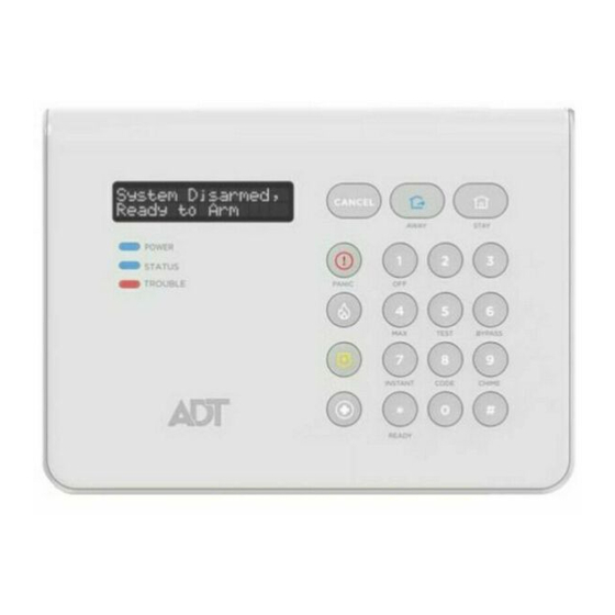
System LED Functions
BATTERY
LED
POWER
STATUS
TROUBLE
Specifications
Dimensions:
Voltage Input:
DETAIL A
4-Hour Backup Battery:
Optional 24-Hour Backup
Battery:
Communication Formats:
Contacting Technical Support
PLEASE, before you call Technical Support, be sure you:
READ THE INSTRUCTIONS!
• Determine that the power supply and/or backup battery are supplying proper
voltages.
• Verify your programming information where applicable.
• Note the proper model number of this product, and the version level (if known)
along with any documentation that came with the product.
• Note your ADT customer number and/or company name.
Having this information handy will make it easier for us to serve you quickly and
effectively.
For Documentation and Online Support
See Installation and Setup Guide P/N 800-24341 or higher, which can be
ordered by contacting Customer Service at 1-800-238-2727 (1-800-ADT-
ASAP). For technical support please call the ADT Product Support Group at
1-877-748-7628, option 3.
Warning: this unit includes an alarm verification feature that will result in a delay of
the system alarm signal from the indicated circuits. The total delay (control unit plus
smoke detectors) shall not exceed 60 seconds. No other smoke detector shall be
connected to these circuits unless approved by the local authority having jurisdiction.
Avertissement: Cette unité peut être programmée pour utiliser une fonction de
vérification d'alarme d'incendie qui entraîne un délai dans la signalisation des
alarmes provenant des circuits dédiés à l'incendie. Le délai total (unité de commande
et détecteurs de fumée) ne doit pas dépasser 60 secondes. Aucun autre détecteur de
fumée ne doit être raccordé à ces circuits sans l'approbation des autorités
compétentes locales.
Note Each protected circuit within this control is supervised.
→ Wi-Fi Settings → Scan for Network OR
Master User Code
Status
Green – Steady
AC Connected/Battery Charged
Red – Blinking
Low Battery
Off
No AC Power
Green – Steady
System is Ready to Arm
Red – Steady
System Armed
Red – Flashing
Alarm or Alarm Memory
Red – Flashing
System is in Programming Mode
Alternately with
TROUBLE LED
(Flashing Amber)
Off
System is Not Ready to Am
Amber – Steady
System Trouble
Amber Flashing
Device Trouble
Amber – Flashing
System is in Programming Mode
Alternately with
STATUS LED
(Flashing Red)
Off
Normal System Status (No Troubles Present)
7.93" W x 5.76" H x 1.10" D
P/N 300-10260: White – 9VDC, 2.5A
P/N 300-10260-BK (Black) – 9VDC, 2.5A
P/N 300-10342: Rechargeable Backup Battery:
Lithium-ion battery pack rated at 3.6V, 2480AH
P/N 300-10186PK: Rechargeable Backup Battery Kit:
Lithium-ion battery pack rated at 3.6/4.2V, 7500 mAH
4-Digit Contact ID
Meaning
Advertisement
Table of Contents

Related Manuals for ADT ADT2X16AIO


Summary of Contents for ADT ADT2X16AIO
- Page 1 Note: Do not connect to a receptacle controlled by a switch. Plug the power supply into a 24-hour, 110VAC unswitched outlet. Upon power- The ADT ADT2X16AIO is designed to be placed on a desk/table top with the stand up, the “Please Standby!” will be displayed on the home screen.
- Page 2 Responsible Party / Issuer of Supplier’s Declaration of Conformity: Honeywell International, 2 www.honeywell.com/security/hsc/resources/wa. Corporate Center Drive., Melville, NY 11747, Ph: 516-577-2000 Patents Warranty For patent information, see www.honeywell.com/patents ADT Security Services, Inc. 1501 Yamato Road Boca Raton, FL 33431 Copyright © 2018 ADT Security Services Ê800-24343ÁŠ 800-24343 5/18 Rev. A...
Need help?
Do you have a question about the ADT2X16AIO and is the answer not in the manual?
Questions and answers