
Related Manuals for Mitsubishi Electric k-con KSGD-01WS-B

Summary of Contents for Mitsubishi Electric k-con KSGD-01WS-B
- Page 1 Refrigerant leak detector Installation and operation manual Version 1.4 Manufactured for MITSUBISHI ELECTRIC UK KSGD-01WS-B Installation and operation manual KSGD02 Revision: 1.4 Page 1 of 16...
- Page 2 All rights reserved The information contained in this manual has been carefully checked and is believed to be accurate. However, the manufacturer assumes no responsibility for any inaccuracies that may be contained herein. In no event will the manufacturer, be liable for any direct, indirect, special, incidental, or consequential damages resulting from any defect or omission in this manual, even if advised of the possibility of such damages.
-
Page 3: Table Of Contents
Contents Safety Precautions ..................................4 1. Overview..................................... 7 1.1 Specification Overview ..............................7 2. Installation ....................................8 2.1 Locating the sensor ............................... 8 2.2 Electrical connections..............................9 2.3 Other features ................................10 3. Operation ....................................11 3.1 Operational matrix ............................... 11 4. -
Page 4: Safety Precautions
Do not reconstruct or change the settings of the protection devices. If the pressure switch, thermal switch, or other protection device is shorted or operated forcibly, or parts other than those specified by Mitsubishi Electric are used, fire or explosion may result. - Page 5 Precautions for devices that use HCFC and HFC refrigerants Caution: Do not use the existing refrigerant piping. The old refrigerant and refrigerator oil in the existing piping contains a large amount of chlorine which may cause the refrigerator oil of the new unit to deteriorate. Use refrigerant piping made of C1220 (CU-DHP) phosphorus deoxidized copper as specified in the JIS H3300"...
- Page 6 Warning: Mitsubishi Electric UK assumes no liability for damages consequent to the user of this product. We reserve the right to change this manual at any time without notice. The information furnished by us is believed to be accurate and reliable. However, no responsibility is assumed by us for its use, nor for any infringements of patents or other rights of third parties resulting from its use.
-
Page 7: Overview
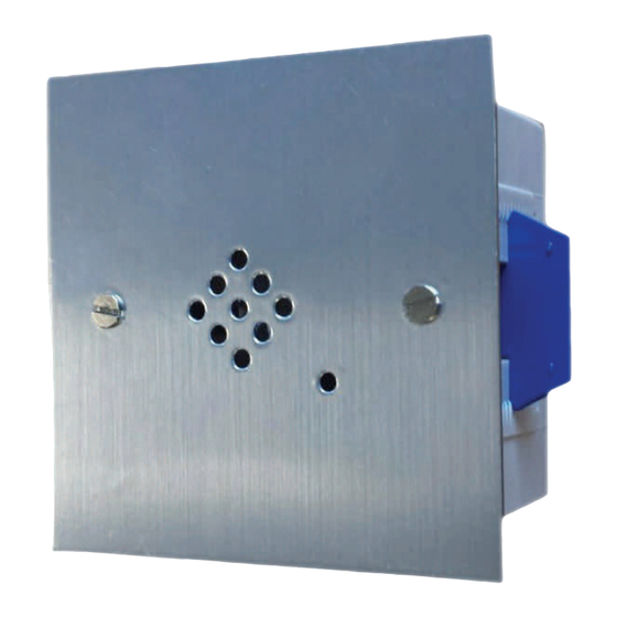
1. Overview This manual outlines the installation and operation of the KSGD refrigerant leak detector. The KSGD is a stand-alone refrigerant leak detector for air conditioning and refrigeration applications. The KSGD is available in a number variants this manual covers all of these variants. Fig 1 KSGD detector 1.1 Specification Overview... -
Page 8: Installation
2. Installation The KSGD is available with faceplates in white plastic and stainless steel or can be custom finished to suit colour schemes. Irrespective of the faceplate the KSGD will fit into a standard single gang electrical back box. The minimum depth of the back box is dependent upon the faceplate however all designs will fit into a box 45mm deep enclosure which can be flush mounted into... -
Page 9: Electrical Connections
2.2 Electrical connections The KSGD connections are located on the rear of the detector PCB. The KSGD will operate from a 12/24 volt AC or DC supply. Start-up current from a 24 volt AC supply is 260mA with steady state of 100mA. A single plug on the PCB accepts all the electrical connections. A small flat bladed screwdriver can be used to prise the plug away from the socket. -
Page 10: Other Features
2.3 Other features Features such as the sensor and buzzer enable link are located on the front of the detector PCB. Status LED Buzzer Buzzer Enable / Disable link Sensor Factory use only Fig 2.4 KSGD other features When the buzzer enable / disable link is fitted, the buzzer will operate when required. Remove this link to disable the buzzer permanently. -
Page 11: Operation
3. Operation When power is applied, a green LED will flash (GREEN/RED) approximately 5 minutes the green LED will be illuminated permanently and the detector is fully operational. When a refrigerant leak alarm is detected the LED will flash RED/AMBER, the buzzer will sound and the relay(s) will change status. -
Page 12: Testing
4. Testing The operation of the detector can be verified in 2 ways depending on the accuracy required; 4.1 Measuring the Gv When testing the detector the Gv voltage must be checked using a multi-meter at various points during the test procedure. The Gv voltage is measured on the 6 way test / calibration connector. The location of this connector varies on older variants of the detector, along with the connection terminals. -
Page 13: Full Operational Test Procedure
4.2 Full Operational test procedure To verify the correct operation of the detector, test gas can be used which is equivalent to the alarm thresholds. Test kits are available. Fig 4.3 Calibration test kit Fit pressure regulator on to calibrated gas bottle and check the cylinder pressure is above 10 bar. -
Page 14: Fault Finding
Pre-alarm level 2 Once the state is reached, the operation of the detector is proven and unless confirmation of the relay operation is required there is no necessity to continue through the remaining steps skip to step 5. If the detector remains in the Pre-alarm level 2 state continuously for 30 minutes the detector will enter the... -
Page 15: Revisions
Revisions 11/12/2019 First released version - KR KSGD-01WS-B Installation and operation manual KSGD02 Revision: 1.4 Page 15 of 16... -
Page 16: Notes
Notes KSGD-01WS-B Installation and operation manual KSGD02 Revision: 1.4 Page 16 of 16...