
Related Manuals for GE CSWONBLPWF1


Summary of Contents for GE CSWONBLPWF1
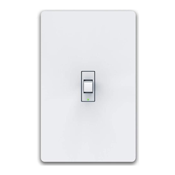
- Page 1 ™ Smart Wall Switch Installation Guide Toggle or Paddle Models CSWONBLPWF1 CSWONBLTWF1...
- Page 2 WARNING: RISK OF ELECTRIC SHOCK This product installation requires handling 120 volt wiring. Follow each step carefully. If any concerns handling wiring, hire a qualified electrician. Ensure all work meets applicable local and national codes.
- Page 3 Simple DIY Setup Install Download your Smart the C by GE app your Smart Switch to Switch the C by GE app...
-
Page 4: Compatibility Requirements
Compatibility Requirements Rating 120V AC 60Hz Works with halogen, incandescent and LED bulbs, Neutral wire is required including C by GE Smart (Wire is usually white Bulbs. or grey) LED up to 1.25 amps Ground wire is required (Wire is usually green,... - Page 5 Let’s Do It INCLUDED Switch Wall Plate 4 Wire Nuts 4 Phillips Mounting Screws Line Load Ground Neutral Wire Labels YOU’LL NEED Phillips Screwdriver Needle Nose Pliers Approximately (recommended) 30 minutes of your day to install and setup the switch Voltage Tester (recommended)
- Page 6 You Got This! And we’re here to help. For in-depth instructional videos and a guided tour through the installation, go to cbyge.com/switch-support.
-
Page 7: Turn Off The Power
BEFORE YOU DO ANYTHING: Step 1 Turn Off The Power! 1. Turn off the power for the switch location at the circuit breaker box. 2. Test existing switch by toggling switch on/off, ensuring lights do not turn on. 3. Now, follow these setup steps for a single gang switch. - Page 8 3. Before disconnecting the wires from the wall, label each with the provided wire labels. Neutral and ground wires are required. If you don’t have either wire, the C by GE switch is not compatible. 4. Disconnect wires and remove existing switch.
- Page 9 Neutral Line Load Ground Neutral Wire Labels...
-
Page 10: Connect The Wires
STEP 3 Connect The Wires 1. Connect the neutral (white) wire on the switch to the neutral (white label) wire from the wall. 2. Connect the line (black) wire on the switch to the line (black label) wire from the wall. 3. - Page 11 3/4 inch USING WIRE NUTS 1. Insert wires into wire nut. 2. Turn wire nut clockwise. 3. Pull gently on wires to test connection.
- Page 12 STEP 4 Fit Wires Into Wall Box Neatly push the wires back into the box, rotating the switch so it’s oriented according to the image. Load Toggle Paddle Ground Switch Line Neutral...
-
Page 13: Secure The Switch
STEP 5 Secure The Switch 1. Using a Phillips screwdriver and the screws provided, secure the switch to the wall until level and flush. 2. Screw on the faceplate bracket, then snap the faceplate cover onto the bracket. Toggle Paddle... - Page 14 STEP 6 Turn The Power Back On After the switch is secured and faceplate mounted, turn the power back on at the circuit breaker box. At the switch, the light ring will flash blue indicating the device is wired correctly and the device is in setup mode.
- Page 15 Light ring will continuously flash blue until the switch is added to the C by GE app. Light ring will flash red if the circuit is overloaded. Max load rating 1.25 amps for LED and 5 amps for incandescent/halogen. Light ring will not illuminate if wired incorrectly.
- Page 16 Congratulations! You’ve completed the Smart Switch installation. Next... Download Setup the C by GE app your Smart Switch to your Alexa or the C by GE app Google voice assistant (optional)
- Page 17 Enable Your Voice Assistant Amazon Alexa To setup, open the Alexa app, search for the C by GE skill, follow the setup instructions. Try this... Alexa, turn off the living room. Alexa, turn on the bedroom. Google Assistant To setup, open the Google Assistant or Google Home app, search for the C by GE action, follow the setup instructions.
- Page 18 Additional Information and Warnings FCC Compliance Statement Compliance Notice: This equipment has been tested and found to comply with the limits for a Class B digital device, pursuant to part 15 of the FCC Rules. These limits are designed to provide reasonable protection against harmful interference in a residential installation.
- Page 19 RF Exposure Information: This equipment complies with FCC radiation exposure limits set forth for an uncontrolled environment. In order to avoid the possibility of exceeding the FCC radio frequency exposure limits, human proximity to the antenna shall not be less than 8 inches during normal operation.