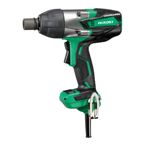
Hitachi WR 16SE Repair Manual
Hide thumbs
Also See for WR 16SE:
- Instruction manual and safety instructions (40 pages) ,
- Handling instructions manual (8 pages) ,
- Handling instructions manual (100 pages)
Advertisement
Quick Links
PRODUCT NAME
Hitachi Impact Wrench
WR 16SE
Model
CONTENTS
REPAIR GUIDE ----------------------------------------------------------------------------------------------------------------- 1
1. Precautions on disassembly and reassembly ------------------------------------------------------------- 1
STANDARD REPAIR TIME (UNIT) SCHEDULE ---------------------------------------------------------------------- 11
LIST No.
LIST No.
WR 16SE: E727
xxx. 2014
Sep. 2014
International Sales Division
W
Advertisement

Summary of Contents for Hitachi WR 16SE
- Page 1 LIST No. LIST No. WR 16SE: E727 xxx. 2014 Sep. 2014 PRODUCT NAME Hitachi Impact Wrench WR 16SE Model CONTENTS REPAIR GUIDE ----------------------------------------------------------------------------------------------------------------- 1 1. Precautions on disassembly and reassembly ------------------------------------------------------------- 1 STANDARD REPAIR TIME (UNIT) SCHEDULE ---------------------------------------------------------------------- 11 International Sales Division...
- Page 2 1. Precautions on disassembly and reassembly [Bold] numbers in the descriptions below correspond to the numbers in the Parts List and exploded assembly diagram for the Model WR 16SE. Disassembly 1. Removal of the hammer case ass’y (1) Insert a flat-blade screwdriver into a gap between Bumper (A) [1] and the Hammer Case Ass'y [3], and then remove Bumper (A) [1].
- Page 3 3. Removal of housing (A).(B) set (1) Remove the eight Tapping Screws D4 x 20 [42]. You can now remove housing (B) of Housing (A).(B) Set [29]. (2) Remove the two Tapping Screws D4 x 16 [37] and the Cord Clip [36]. You can now remove Inner Cover (A) [23], Rotor Ass'y [25], Stator IGBT PCB [28], Controller (A) [33], Controller (B) [40], Switch [32], and Cord [39] together.
- Page 4 5. Disassembly of the stator IGBT PCB, inner cover (A), and rotor (1) Firmly hold Inner Cover (A) [23] so as not to be attracted by the magnetic force of the Rotor Ass'y [25], and then pull out the stator of the Stator IGBT PCB [28] in direction “A” as shown below. (2) Keep Inner Cover (A) [23] away from the fan of the Rotor Ass'y [25], use a hand press or similar tool to press the end of the pinion of the Rotor Ass'y [25], and then remove Inner Cover (A) [23] from the Rotor Ass'y [25].
- Page 5 Reassembly Reverse the disassembly procedures above to reassemble the impact wrench. However, when reassembling the impact wrench, pay particular attention to the following items. 1. Reassembly of the power supply portion and its vicinity (1) For replacement of the Switch [32], Controller (A) [33], Controller (B) [40], and the Stator IGBT PCB [28], connect these parts correctly with wires according to the wiring diagram.
- Page 6 Fig. 4 [28] Connector cable Internal wire (red) [32] Internal wire (black) Four internal wires [34] Apply silicon to the entire connector joint. [33] Internal wire (blue) Internal wire (black) Capacitor [34] Internal wire (white) Internal wire (red) Internal wire (blue) [34] Internal wire (black) Internal wire (black)
- Page 7 Fig. 5 Earth terminal [28] Insert the earth terminal into a gap between the housing rib, screw boss, and Stator IGBT PCB [28]. Screw boss Push the connector cable and internal wire into the wiring groove for internal wire. [32] Push the connector cable and internal wire into a gap between the Switch [32] and housing (A).
- Page 8 2. Reassembly of the impact mechanism components (1) Mount two Washers (B) [12], Hammer Spring (A) [13], Washer (A) [14], and Spindle (A) [17] in this order on Hammer (A) [8], which contains the twenth-nine Steel Balls D3.97 [9]. (2) Match the peak of the cam groove of Spindle (A) [17] with the steel ball insertion groove of Hammer (A) [8].
- Page 9 Application of lubricant (1) Apply Nippeco SEP-3A grease to the following: • Pinion tooth flanks of the Rotor Ass’y [25] • Tooth flanks of the Ring Gear [19] • Tooth flanks and inner circumference of the Idle Gear Set (2 pcs.) [18] •...
- Page 10 Wiring diagram Carefully ensure that wiring is accomplished as illustrated below, because incorrect wiring will result in inadequate or reverse rotation. Fig. 7 • Wiring diagram Stator IGBT PCB [28] Insert the earth terminal here among the housing rib, screw boss, and Stator IGBT PCB [28].
- Page 11 Fig. 8 • Connecting diagram Stator IGBT PCB [28] Switch [32] Flat cable (C) 8PIN Connector cable (E) 18PIN Controller (A) [33] Controller (B) [40] -10-...
- Page 12 STANDARD REPAIR TIME (UNIT) SCHEDULE Variable MODEL 60 min. Fixed Work Flow WR 16SE Switch Housing Controller (A).(B) Set Stator IGBT Controller Cord Rotor Ass'y Cord Armor Ball Bearing (608DD) Ball Bearing (624DD) Inner Cover (A) Ball Bearing (6807) General Assembly...
- Page 13 LIST NO. E727 IMPACT WRENCH 2014 · 9 · 10 Model WR 16SE (E1)
- Page 14 PARTS WR 16SE ITEM DESCRIPTION REMARKS CODE NO. USED 337721 BUMPER (A) 323753 SEAL LOCK HEX. SOCKET HD. BOLT M5 X 35 337195 HAMMER CASE ASS'Y INCLUD.1,4,5 318704 O-RING (M) 323766 METAL 334341 ANVIL (L) TYPE FOR W/O PLUNGER(A),PIN RETAINER(A)
- Page 15 PARTS WR 16SE ITEM DESCRIPTION REMARKS CODE NO. USED 500423Z CORD (CORD ARMOR D8.8) FOR UAE (230V-240V) 500470Z CORD (CORD ARMOR D8.8) FOR UAE (110V) 500201Z CORD (CORD ARMOR D10.1) FOR THA 500234Z CORD (CORD ARMOR D8.8) FOR VIE 500456Z CORD (CORD ARMOR D8.8) FOR CHN...
- Page 16 OPTIONAL ACCESSORIES WR 16SE ITEM CODE NO. DESCRIPTION REMARKS USED CORNER ATTACHMENT EW-14R INCLUD.602-618 955300 HOUSING 955301 METAL 955302 SPINDLE 945251 HITACHI LABEL 955303 BEARING RACE 955304 NEEDLE THRUST BEARING (NTA-1413) 955305 COVER 955306 NEEDLE BEARING (NTN BK1012) 948227 RETAINING RING FOR D47 HOLE...


