Siemens SIMATIC NET Installation Manual
Rugged ethernet switches
Hide thumbs
Also See for SIMATIC NET:
- Configuration manual (464 pages) ,
- System manual (372 pages) ,
- Manual (300 pages)

Related Manuals for Siemens SIMATIC NET


Summary of Contents for Siemens SIMATIC NET
- Page 1 Installation Manual SIMATIC NET Rugged Ethernet Switches RUGGEDCOM RMC30 Edition 04/2021 https://www.siemens.com...
- Page 2 Preface Introduction Installing the Device SIMATIC NET Device Management Rugged Ethernet Switches RUGGEDCOM RMC30 Communication Ports Technical Specifications Installation Manual Certification 04/2021 C79000-G8976-1008-10...
- Page 3 Note the following: WARNING Siemens products may only be used for the applications described in the catalog and in the relevant technical documentation. If products and components from other manufacturers are used, these must be recommended or approved by Siemens. Proper transport, storage, installation, assembly, commissioning, operation and maintenance are required to ensure that the products operate safely and without any problems.
-
Page 4: Table Of Contents
Accessing Documentation ....................... v Registered Trademarks ......................v Warranty ..........................v Training ..........................vi Customer Support ........................vi Contacting Siemens ....................... vii Introduction ........................... 1 Feature Highlights ....................1 Description ......................2 Required Tools and Materials ................. 3 Decommissioning and Disposal ................3 Installing the Device ...................... - Page 5 Table of Contents Operating Environment ..................22 Mechanical Specifications ..................22 Dimension Drawings ................... 22 Certification ......................... 25 Approvals ......................25 6.1.1 CSA ........................25 6.1.2 European Union (EU) ..................25 6.1.3 FCC ........................26 6.1.4 FDA/CDRH ......................26 6.1.5 ISED ........................
-
Page 6: Preface
Warranty Siemens warrants this product for a period of five (5) years from the date of purchase, conditional upon the return to factory for maintenance during the warranty term. This product contains no user-serviceable parts. Attempted service by unauthorized personnel shall render all warranties null and void. -
Page 7: Training
Siemens Sales representative. Customer Support Customer support is available 24 hours, 7 days a week for all Siemens customers. For technical support or general information, contact Siemens Customer Support through any of the following methods: Online Visit http://www.siemens.com/automation/support-request... -
Page 8: Contacting Siemens
Preface Contacting Siemens • Ask questions or share knowledge with fellow Siemens customers and the support community Contacting Siemens Address Siemens AG Industry Sector 300 Applewood Crescent Concord, Ontario Canada, L4K 5C7 Telephone Toll-free: 1 888 264 0006 Tel: +1 905 856 5288... - Page 9 Preface Contacting Siemens viii RUGGEDCOM RMC30 Installation Manual, 04/2021, C79000-G8976-1008-10...
-
Page 10: Introduction
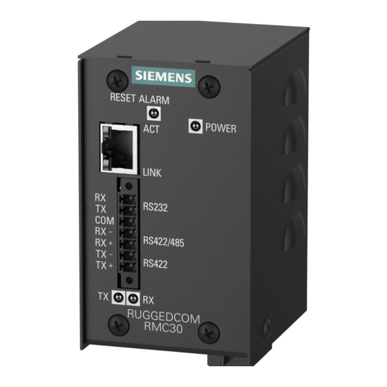
Introduction The RUGGEDCOM RMC30 is an industrially hardened, 2-port Serial-to-Ethernet server that has been specifically designed to operate in electrically harsh and climatically demanding environments. The RUGGEDCOM RMC30 allows communication with virtually any serial device via Ethernet, providing simple and reliable network connectivity. -
Page 11: Description
Introduction 1.2 Description • Support multiple Modbus masters • Use Serial IP port redirection software to support PC applications statistics and built-in sniffer for troubleshooting Designed for Harsh Environments • Operates over a temperature range of -40 to 85 °C (-40 to 185 °F) without the use of fans for improved reliability •... -
Page 12: Required Tools And Materials
Introduction 1.3 Required Tools and Materials State Description Green Power is on Power is off RESET Button Shuts down and restarts the device. For more information, refer to "Resetting the Device (Page 14)". TX/RX LEDs Indicate the connection status of the serial terminal. State Description Green... - Page 13 Introduction 1.4 Decommissioning and Disposal Decommissioning This device may include sensitive, proprietary data. Before taking the device out of service, either permanently or for maintenance by a third-party, make sure it has been fully decommissioned. For more information, refer to the associated Configuration Manual. Recycling and Disposal For environmentally friendly recycling and disposal of this device and related accessories, contact a facility certified to dispose of waste electrical and electronic...
-
Page 14: Installing The Device
This product contains no user-serviceable parts. Attempted service by unauthorized personnel shall render all warranties null and void. Changes or modifications not expressly approved by Siemens AG could invalidate specifications, test results, and agency approvals, and void the user's authority to operate the equipment. -
Page 15: General Procedure
Visually inspect each item in the package for any physical damage. Verify all items are included. Note If any item is missing or damaged, contact Siemens for assistance. Mounting the Device The RUGGEDCOM RMC30 is designed for maximum mounting and display flexibility. -
Page 16: Mounting The Device On A Din Rail
Installing the Device 2.3.1 Mounting the Device on a DIN Rail Forced airflow is not required. However, any increase in airflow will result in a reduction of ambient temperature and improve the long-term reliability of all equipment mounted in the rack space. Note For detailed dimensions of the device with either DIN rail or panel hardware installed, refer to... - Page 17 Installing the Device 2.3.1 Mounting the Device on a DIN Rail Removing the Device To remove the device from a DIN rail, do the following: Insert a flathead screwdriver into the slot of the sliding release and move it down. DIN Rail DIN Rail Adapter Figure 2.2 Removing the Device from a DIN Rail...
-
Page 18: 2.3.2 Mounting The Device To A Panel
Installing the Device 2.3.2 Mounting the Device to a Panel 2.3.2 Mounting the Device to a Panel To mount the device to a panel, do the following: Disassemble the device and panel adapter. Remove the screw at the bottom of the adapter. Pull the device out of the adapter. -
Page 19: 2.4.1 Connecting Ac Power
Note Siemens requires the use of external surge protection in VDSL applications where the line may be subject to surges greater than that for which the device is rated. Use the following specifications as a guide for VDSL external surge protection: •... - Page 20 Installing the Device 2.4.1 Connecting AC Power Connect the positive wire from the power source to the positive/live (+/L) terminal on the terminal block. Positive/Live (+/L) Terminal Negative/Neutral (-/N) Terminal Surge Ground Terminal Braided Ground Cable Figure 2.4 Terminal Block Wiring Connect the negative wire from the power source to the negative/neutral (-/N) terminal on the terminal block.
-
Page 21: 2.4.2 Connecting Dc Power
Installing the Device 2.4.2 Connecting DC Power 2.4.2 Connecting DC Power To connect a high or low DC power supply to the device, do the following: NOTICE Electrical hazard – risk of damage to equipment Before testing the dielectric strength (HIPOT) in the field, remove the braided ground cable connected to the surge ground terminal and chassis ground. -
Page 22: Device Management
Device Management This section describes how to connect to and manage the device. Connecting to the Device The following describes the various methods for accessing the RUGGEDCOM RMC30 console and Web interfaces on the device. For more detailed instructions, refer to the RUGGEDCOM ROS Configuration Manual for the RUGGEDCOM RMC30. -
Page 23: Resetting The Device
Device Management 3.3 Resetting the Device Resetting the Device The RUGGEDCOM RMC30 can be reset (rebooted) using the RESET button. The RESET button is recessed and can only be reached using a pin or small screwdriver. To reset the device, quickly press and release the RESET button with a pin. RUGGEDCOM RMC30 Installation Manual, 04/2021, C79000-G8976-1008-10... -
Page 24: Communication Ports
Communication Ports The RUGGEDCOM RMC30 can be equipped with various types of communication ports to enhance its abilities and performance. Port 1 Port 2 Figure 4.1 Port Assignment Port Type Copper Ethernet Port RS232/RS485/RS422 Serial Terminal Copper Ethernet Port The RUGGEDCOM RMC30 supports a single 10Base-TX Ethernet port that allows connection to a standard Category 5 (CAT-5) unshielded twisted-pair (UTP) cable with an RJ45 male connector. - Page 25 Communication Ports 4.1 Copper Ethernet Port excessive noise and interference, but more importantly, create a potential shock hazard that can result in serious injury. NOTICE For substation applications, do not use the copper Ethernet port to interface with field devices across distances that could produce high levels of ground potential rise (i.e.
-
Page 26: Serial Terminal
Transmit (Tx), Receive (Rx) and Common (COM). Note The RS232 port is intended for point-to-point applications only. In adherence to the EIA/TIA guidelines for RS232 communications, the following is recommended by Siemens: • Always use shielded cabling to minimize the effects of ambient electrical noise •... -
Page 27: 4.2.2 Rs485/422 Data Ports
Communication Ports 4.2.2 RS485/422 Data Ports Serial Terminal DB9 Console Port Figure 4.4 RS232 Port to Console Port Pin Configuration DB9 Pin Name Description Reserved (Do Not Connect) Receive Data Transmit Data Reserved (Do Not Connect) SGND Signal Ground Reserved (Do Not Connect) Reserved (Do Not Connect) Reserved (Do Not Connect) Reserved (Do Not Connect) - Page 28 Communication Ports 4.2.2 RS485/422 Data Ports and RS422 can accommodate multi-drop networks, for master-slave serial network communications. For both RS485/RS422 connections, the following general guidelines should be followed: • To minimize the effects of ambient electrical noise, use shielded cabling. • The correct polarity must be observed throughout a single sequence or ring.
- Page 29 Communication Ports 4.2.2 RS485/422 Data Ports 120Ω 10nF RUGGEDCOM RMC30 Device With Built-In Termination Common (Isolated Ground) Negative Positive Shield to Earth (Connected At a Single Point) RS485 Devices (32 Total) Figure 4.5 Recommended RS485 Wiring RUGGEDCOM RMC30 Installation Manual, 04/2021, C79000-G8976-1008-10...
-
Page 30: Technical Specifications
Technical Specifications This section provides important technical specifications related to the device and available modules. Power Supply Specifications Power Minimum Input Maximum Input Internal Max. Power Supply Type Fuse Rating Consumption 24 VDC 18 VDC 36 VDC 3.15A (T) 48 VDC 36 VDC 59 VDC 88 VDC... -
Page 31: Operating Environment
Technical Specifications 5.4 Operating Environment Parameter 10Base-FL 100Base-FX Notes IEEE 802.3x Yes No Yes No Full Duplex, Flow Control Operating Environment Parameter Range Comments Ambient Operating Temperature -40 to 85 °C Measured from a 30 cm (12 in) radius (-40 to 185 °F) surrounding the center of the enclosure. - Page 32 Technical Specifications 5.6 Dimension Drawings 92.8 80.1 73.7 62.2 58.4 70.7 Figure 5.1 Overall Dimensions 67.3 62.2 96.1 58.4 82.2 35.6 11.4 Figure 5.2 Panel Mount Dimensions RUGGEDCOM RMC30 Installation Manual, 04/2021, C79000-G8976-1008-10...
- Page 33 Technical Specifications 5.6 Dimension Drawings RUGGEDCOM RMC30 Installation Manual, 04/2021, C79000-G8976-1008-10...
-
Page 34: Certification
UL 62368-1 Information Technology Equipment – Safety – Part 1: General Requirements) 6.1.2 European Union (EU) This device is declared by Siemens AG to comply with essential requirements and other relevant provisions of the following EU directives: • EN 62368-1 Information Technology Equipment –... -
Page 35: 6.1.3 Fcc
Certification 6.1.3 FCC The device is marked with a CE marking and can be used throughout the European community. A copy of the CE Declaration of Conformity is available from Siemens AG. For contact information, refer to "Contacting Siemens (Page vii)". -
Page 36: Acma
A copy of the Declaration of Conformity is available via Siemens Industry Online Support at https://support.industry.siemens.com/cs/ww/en/view/89855782. 6.1.8 RoHS This device is declared by Siemens AG to meet the requirements of the following RoHS (Restriction of Hazardous Substances) directives for the restricted use of certain hazardous substances in electrical and electronic equipment: •... -
Page 37: Emc And Environmental Type Tests
Certification 6.2 EMC and Environmental Type Tests EMC and Environmental Type Tests The RUGGEDCOM RMC30 has passed the following EMC and environmental tests. IEC 61850-3 Type Tests Test Description Test Levels Severity Levels Enclosure ± 8 kV 61000-4-2 Contact Enclosure Air ±... - Page 38 Ports AC Power 5 kV Ports Siemens specified severity level. IEEE 1613 EMC Immunity Type Tests Note The RUGGEDCOM RMC30 meets Class 2 requirements for an all-fiber configuration and Class 1 requirements for copper ports. Description Test Levels Enclosure Contact ±...
- Page 39 Certification 6.2 EMC and Environmental Type Tests Test Description Test Levels Severity Levels IEC 60255-21-1 Vibration 2 g @ 10-150 Hz Class 2 IEC 60255-21-2 Shock 30 g @ 11 ms Class 2 RUGGEDCOM RMC30 Installation Manual, 04/2021, C79000-G8976-1008-10...
- Page 40 Further Information Siemens RUGGEDCOM https://www.siemens.com/ruggedcom Industry Online Support (service and support) https://support.industry.siemens.com Industry Mall https://mall.industry.siemens.com Siemens AG Digital Industry Process Automation Postfach 48 48 90026 NÜRNBERG GERMANY...