Siemens SIMATIC NET Operating Instructions Manual
Network components/profibus, optical link module
Hide thumbs
Also See for SIMATIC NET:
- Configuration manual (464 pages) ,
- System manual (372 pages) ,
- Manual (300 pages)
Table of Contents
Advertisement
Quick Links
Optical link module
SIMATIC NET
Network components/PROFIBUS
Optical link module
Operating Instructions
01/2020
C79000-G8976-C270-06
Introduction
Description of the device
Commissioning
Operator control (hardware)
Mounting
Connection
Planning/configuring
Service and maintenance
Troubleshooting/FAQs
Technical data
Dimension drawings
Approvals
Appendix
1
2
3
4
5
6
7
8
9
10
11
12
A
Advertisement
Table of Contents

Related Manuals for Siemens SIMATIC NET


Summary of Contents for Siemens SIMATIC NET
- Page 1 Optical link module Introduction Description of the device Commissioning SIMATIC NET Operator control (hardware) Network components/PROFIBUS Optical link module Mounting Connection Operating Instructions Planning/configuring Service and maintenance Troubleshooting/FAQs Technical data Dimension drawings Approvals Appendix 01/2020 C79000-G8976-C270-06...
- Page 2 Note the following: WARNING Siemens products may only be used for the applications described in the catalog and in the relevant technical documentation. If products and components from other manufacturers are used, these must be recommended or approved by Siemens. Proper transport, storage, installation, assembly, commissioning, operation and maintenance are required to ensure that the products operate safely and without any problems.
-
Page 3: Table Of Contents
Table of contents Introduction ............................. 5 Description of the device ......................... 9 Product overview ........................9 Device view of an OLM ......................10 Properties and functions ......................11 Area of application ........................13 LED display ..........................13 2.5.1 Overview ..........................13 2.5.2 "SYSTEM"... - Page 4 Table of contents Network topologies ........................ 53 7.1.1 Possible network topologies ....................53 7.1.2 Installation guide ........................53 7.1.3 Bus topology .......................... 54 7.1.4 Star topology .......................... 57 7.1.5 Ring topology ......................... 59 7.1.5.1 Redundant optical ring ......................59 7.1.5.2 Redundant optical ring with two OLMs ..................
-
Page 5: Introduction
(Optical Link Modules). Validity of the Operating Instructions These operating instructions apply to the following devices: ● SIMATIC NET OLM / P11 V4.1 ● SIMATIC NET OLM / P12 V4.1 ● SIMATIC NET OLM / P22 V4.1 ● SIMATIC NET OLM / G11 V4.0 ●... - Page 6 Introduction Further documentation You will find more information on other SIMATIC NET products that you can use with the OLM devices in the “SIMATIC NET PROFIBUS networks SIEMENS AG” manual. Article numbers: ● C79000-G8900-C124-xx German ● C79000-G8976-C124-xx English ● C79000-G8977-C124-xx French ●...
- Page 7 Siemens’ products and solutions undergo continuous development to make them more secure. Siemens strongly recommends that product updates are applied as soon as they are available and that the latest product versions are used. Use of product versions that are no longer supported, and failure to apply the latest updates may increase customers’...
- Page 8 Introduction Optical link module Operating Instructions, 01/2020, C79000-G8976-C270-06...
-
Page 9: Description Of The Device
Description of the device Product overview Article numbers Device Article number SIMATIC NET OLM / P11 V4.1 6GK1 503-2CA01 SIMATIC NET OLM / P12 V4.1 6GK1 503-3CA01 SIMATIC NET OLM / P22 V4.1 6GK1 503-4CA01 SIMATIC NET OLM / G11 V4.0 6GK1 503-2CB00 SIMATIC NET OLM / G12 V4.0... -
Page 10: Device View Of An Olm
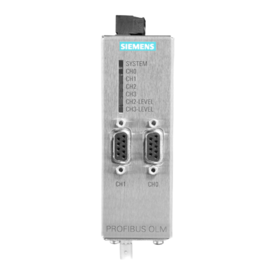
Description of the device 2.2 Device view of an OLM Device view of an OLM The following figure shows a PROFIBUS OLM with all interfaces, display elements and setting options. ① LED display ② Channel 1/0 (RS-485) ③ Channel 2 (optical) Transmitter (left) •... -
Page 11: Properties And Functions
Description of the device 2.3 Properties and functions Properties and functions Device design Every module has two (OLM P11, G11), three (OLM P12, G12) or four (OLM P22, G22) independent channels (ports) that consist of a transmitter and a receiver part. The power supply voltage for operation is 24 VDC. - Page 12 Description of the device 2.3 Properties and functions Note BFOC BFOC stands for Bayonet Fiber Optic Connector. This connector type is functionally compatible with ST connectors. ST is a registered trademark of the AT&T company. ® Note PFC stands for Polymer Cladded Fiber and is synonymous with HCS .
-
Page 13: Area Of Application
Description of the device 2.4 Area of application Area of application PROFIBUS OLMs are designed for use in optical PROFIBUS fieldbus networks. They allow the conversion of electrical PROFIBUS interfaces (RS-485 level) into optical PROFIBUS interfaces and vice versa. The modules can be integrated in existing PROFIBUS fieldbus networks with the known advantages of optical transmission technology. - Page 14 Description of the device 2.5 LED display LED color LED status Meaning Signaling contact Flashing Transmission rate not yet detected because: Does not signal There is no transmitting bus node • There is no connection to a partner module that is trans- •...
-
Page 15: Led "Ch1"/"Ch0" - Electrical
Description of the device 2.5 LED display 2.5.3 LED "CH1"/"CH0" - electrical LED color LED status Meaning Signaling contact Bus node is not connected, because: Does not signal Connected bus node is not turned on • Interruption of one or both wires of the RS-485 bus cable •... -
Page 16: Led "Ch2"/"Ch3" - Optical
Description of the device 2.5 LED display 2.5.4 LED "CH2"/"CH3" - optical Mode "bus with fiber-optic link monitoring and "redundant optical ring" LED color LED status Meaning Signaling contact Transmission rate not yet detected - "System" LED flashes Does not signal There is no transmitting bus node •... -
Page 17: Led "Ch2-Level"/"Ch3-Level
Description of the device 2.5 LED display LED color LED status Meaning Signaling contact Red/yellow Flashing Signals Periodically occurring problem (see above), loose contact • in a FO cable connector FO cable fiber is loose in the FO cable plug •... -
Page 19: Commissioning
Commissioning Preparation 1. Unpack the OLM and its accessories 2. Check that the consignment is complete and that there has been no damage during transportation. 3. Allow the device to acclimatize for a time to avoid condensation after storage in cold surroundings. - Page 20 Commissioning Factory setting The figure shows the factory setting of the DIL switches: ● Switches S0, S1, S2, S3, S4, S7 and S8 in position "0" ● Switch S5 and S6 in position "1" Optical link module Operating Instructions, 01/2020, C79000-G8976-C270-06...
-
Page 21: Operator Control (Hardware)
Operator control (hardware) Note The OLM must be turned off when you switch over the mode. To achieve this, for example unplug the 5-terminal block. Note Use only the DIP switch settings described in this section. If you use other DIP switch settings, the correct operation of the OLMs is not guaranteed. - Page 22 Operator control (hardware) 4.1 Setting compatibility DIL switch S7 (compatibility) in position 1 Compatibility with SINEC L2FO OLM / P3, -P4, -S3, -S4, -S3-1300, -S4-1300 is turned on. If the DIL switch S7 is set to position 1, the functional compatibility with SINEC L2 optical link modules SINEC L2FO OLM / P3, OLM / P4, OLM / S3, OLM / S4, OLM / S3-1300 and OLM / S4-1300 is turned on.
-
Page 23: Setting The Operating Mode
Operator control (hardware) 4.2 Setting the operating mode Setting the operating mode 4.2.1 Setting the mode of the electrical channel (CH1) Note The following information applies only to the default setting of S7 (S7 = 0); in other words, compatibility turned off. With the DIL switch S0, you set the mode of the electrical channel CH1. -
Page 24: Setting The Mode Of The Electrical Channel (Ch0)
Operator control (hardware) 4.2 Setting the operating mode 4.2.2 Setting the mode of the electrical channel (CH0) Note The following information applies only to the default setting of S7 (S7 = 0); in other words, compatibility turned off. Note OLM / P22 and OLM / G22 only With the DIL switch S8, you set the mode of the electrical channel CH0. -
Page 25: Setting The Mode Of The Optical Channels (Ch2/Ch3)
Operator control (hardware) 4.2 Setting the operating mode 4.2.3 Setting the mode of the optical channels (CH2/CH3) Note The following information applies only to the default setting of S7 (S7 = 0); in other words, compatibility turned off. With the DIL switches S1 and S2, you set the mode of the optical channel CH2. With the DIL switches S3 and S4, you set the mode of the optical channel CH3. - Page 26 Operator control (hardware) 4.2 Setting the operating mode Mode "redundant optical ring" CH2 is set to this mode when S1 and S2 are in position 1. CH3 is set to this mode when S3 and S4 are in position 1. Note Always set the "redundant optical ring"...
-
Page 27: Reducing Optical Transmit Power
Operator control (hardware) 4.3 Reducing optical transmit power Reducing optical transmit power Note With OLM / P11 or OLM / G11, S6 has no function. With the DIL switch S5, you set the transmit power of CH2. With the DIL switch S6, you set the transmit power of CH3. With OLM / P11, OLM / P12 and OLM / P22 OLM / P11, OLM / P12 and OLM / P22 have a high optical transmit power. - Page 28 Operator control (hardware) 4.3 Reducing optical transmit power Overdrive occurs Set S5 to position 0 (reduced) if overdrive occurs on CH2. Set S6 to position 0 (reduced) if overdrive occurs on CH3. Note Detecting overdrive From the LEDs, you can recognize when overdrive occurs, refer to the section "LED display (Page 13)".
- Page 29 Operator control (hardware) 4.3 Reducing optical transmit power Fibers used PCF fiber If you use PCF fibers, set the transmit power "Default" (S5 or S6 in position 1). If you use PCF fibers S 200/230, neither a minimum cable length nor an attenuator is necessary.
-
Page 30: Dil Switches S5 / S6 With Olm / G11-1300 And Olm / G12-1300
Operator control (hardware) 4.4 DIL switches S5 / S6 with OLM / G11-1300 and OLM / G12-1300 DIL switches S5 / S6 with OLM / G11-1300 and OLM / G12-1300 In OLM V4 devices for glass fiber-optic cable (1300 nm), the DIL switches S5 and S6 do not have a function (reduction of optical transmit power not possible). -
Page 31: Mounting
Mounting WARNING If a device is operated in an ambient temperature of more than 50 °C, the temperature of the device housing may be higher than 70 °C. The device must therefore be installed so that it is only accessible to service personnel or users that are aware of the reason for restricted access and the required safety measures at an ambient temperature higher than 50 °C. -
Page 32: Installation Guide
Mounting 5.1 Installation guide Installation guide Electromagnetic compatibility Electromagnetic compatibility (EMC) includes all questions of electrical, magnetic and electromagnetic immunity and emission. To avoid interference affecting electrical systems, these effects must be reduced to a minimum. The essential limiting measures include the configuration, correct connection of bus cables and the suppression of switching inductances;... - Page 33 Handling bus cable shields Note the following points about cable shields: ● Use shielded SIMATIC NET PROFIBUS cables throughout your system. The shields of these cables have an adequate shield density to meet the legal requirements regarding noise emission and immunity.
- Page 34 ● The clamps must make good and largearea contact with the shield. ● Contact SIMATIC NET PROFIBUS cables only using the braided copper shield and not the aluminum foil shield. The foil shield is applied on one side to a plastic foil to increase tearing strength and is therefore non-conductive.
- Page 35 Mounting 5.1 Installation guide Optical power budget, aging and environmental conditions When using OLM V4 devices, make sure that they are not exposed to high temperatures for no good reason. The aging of the devices increases radically in high temperatures. The same applies to the connected fiber-optic cables.
-
Page 36: Types Of Installation
Mounting 5.2 Types of installation Types of installation Types of installation You have the following options for the module: ● On a DIN rail ● With a mounting plate on a flat surface (wall mounting) Requirements Note the following before you mount a module: ●... -
Page 37: Mounting On Din Rails
Mounting 5.3 Mounting on DIN rails Mounting on DIN rails Mounting ① Locking slide Figure 5-3 Mounting a module on a DIN rail To install the module on a 35 mm DIN rail complying with DIN EN 60715, follow the steps below: ①... -
Page 38: Wall Mounting
Mounting 5.4 Wall mounting Wall mounting Mounting To mount the module on a wall, follow the steps below: 1. Unscrew the 3 screws on the right side of the OLM (the side with the type label). 2. Use these 3 screws to secure the mounting plate (MLFB: 6GK1503-8AA00). 3. - Page 39 Mounting 5.4 Wall mounting Figure 5-5 Drilling diagram for the mounting plate Optical link module Operating Instructions, 01/2020, C79000-G8976-C270-06...
- Page 40 Mounting 5.4 Wall mounting Optical link module Operating Instructions, 01/2020, C79000-G8976-C270-06...
-
Page 41: Connection
Connection WARNING The equipment is designed for operation with Safety Extra-Low Voltage (SELV) by a Limited Power Source (LPS). This means that only SELV / LPS complying with IEC 60950-1 / EN 60950-1 / VDE 0805-1 must be connected to the power supply terminals. The power supply unit for the equipment power supply must comply with NEC Class 2, as described by the National Electrical Code (r) (ANSI / NFPA 70). - Page 42 Connection Note Power supply, input and output cabling (I/O cabling) must meet the wiring standards for Class I, Div. 2 - article 501 - 10B National Electric Code. WARNING EXPLOSION HAZARD DO NOT OPEN WHEN ENERGIZED. Safety notices for use according to ATEX and IECEx If you use the device under ATEX or IECEx conditions you must also keep to the following safety notices in addition to the general safety notices for protection against explosion: WARNING...
- Page 43 Connection General notes on use in hazardous areas according to UL-HazLoc and FM WARNING EXPLOSION HAZARD DO NOT DISCONNECT WHILE CIRCUIT IS LIVE UNLESS AREA IS KNOWN TO BE NON-HAZARDOUS. This equipment is suitable for use in Class I, Division 2, Groups A, B, C and D or non- hazardous locations only.
-
Page 44: Electrical Rs-485 Bus Cables
If you have bus connections that leave the building, use FO cables. ● Only use shielded twisted pair for the RS-485 bus cables as described in the manual "SIMATIC NET PROFIBUS Networks". Do not exceed the segment lengths specified there. - Page 45 Connection 6.1 Electrical RS-485 bus cables Information on RS-485 bus cables ● The modules are equipped with one or two electrical ports with the RS-485 level. ● They are designed as a 9-pin D-sub female connector with screw locking mechanism (inner thread UNC 4-40).
-
Page 46: Operating Power Supply
Connection 6.2 Operating power supply Operating power supply Information on the power supply ● The terminal block can be removed from the device to allow cables to be connected. ● Supply the module only with a stabilized safety extra-low voltage according to IEC 60950 / EN 60950-1 / VDE 0805 of 24 VDC (max. -
Page 47: Signaling Contact
Connection 6.3 Signaling contact Signaling contact Information on the signaling contact ● The terminal block can be removed from the device to allow cables to be connected. ● A relay with floating contacts is available for the signaling contact on the 5-terminal block on the top of the module. -
Page 48: Optical Channels
Connection 6.4 Optical channels Optical channels Information on optical channels ● You can measure the receive level of the two optical channels CH2 and CH3 using a normal commercially available voltmeter attached to measurement sockets. ● The voltmeter can be connected and disconnected while the device is operating. ●... - Page 49 Connection 6.4 Optical channels Measuring the receive level 1. Measure the level with a high-resistance, ungrounded voltmeter. 2. Do not connect the ground connector to the housing; otherwise the data traffic could be disturbed. 3. To meet the EMC requirements, the length of the connected measuring cables must not exceed 3 m.
- Page 50 Connection 6.4 Optical channels For a valid measurement, the partner OLM at the other end of the FO cable must send normal PROFIBUS frames. This can be recognized based on the LED display of the partner OLM, see section "LED display (Page 13)". The output voltages at the measurement sockets are influenced by the following factors: ●...
-
Page 51: Connecting Optical Cables
Connection 6.5 Connecting optical cables Connecting optical cables Figure 6-2 View of the module from below with optical channels 2 and 3 (device with two optical channels) Follow the steps below to connect the optical cables: 1. Connect the single modules via a two-core fiber-optic cable with BFOC/2.5 connectors. 2. - Page 52 Connection 6.5 Connecting optical cables 4. Close unused BFOC sockets with the supplied protective caps. – An unused optical channel should be set to the “bus without fiber-optic link monitoring“ mode so that it does not cause a broken fiber-optic cable signal. –...
-
Page 53: Planning/Configuring
Planning/configuring Network topologies 7.1.1 Possible network topologies The following network topologies can be implemented with the PROFIBUS OLM: ● Point-to-point connection ● Bus topology ● Star topology ● Redundant optical ring Combinations of these basic types are also possible. To set up the fiber-optic links of these network topologies, cables with two optical fibers are used. -
Page 54: Bus Topology
Planning/configuring 7.1 Network topologies 7.1.3 Bus topology In a bus (linear) structure, the individual PROFIBUS OLMs are connected by two-fiber cables. At the beginning and at the end of a line, modules with one optical channel are adequate, in between modules with two optical channels are necessary. Figure 7-1 Network structure with an optical bus topology Note... - Page 55 Planning/configuring 7.1 Network topologies Bus topology with fiber-optic link monitoring and segmentation Use this mode especially when you want a disrupted fiber-optic cable segment to be separated from the rest of the network, see section "Setting the mode of the electrical channel (CH1) (Page 23)"...
- Page 56 Planning/configuring 7.1 Network topologies Note Protect the optical channels that are not connected against external light and pollution by protective caps. Bus topology without fiber-optic link monitoring Use this mode when you connect a PROFIBUS OLM with a different fiber-optic component according to the PROFIBUS guideline (optical/electrical converter), which does not send a frame echo and does not expect or tolerate a frame echo.
-
Page 57: Star Topology
Planning/configuring 7.1 Network topologies 7.1.4 Star topology Several modules are grouped together to form an active PROFIBUS star coupler. Further modules are connected to this via two-core fiber-optic cables. The modules of the star coupler are interconnected via the electrical channel (electrical star segment). All OLM types for different fiber-optic cables (plastic, PCF, glass) can be combined via the electrical star segment. - Page 58 Planning/configuring 7.1 Network topologies To set up an active PROFIBUS star coupler, modules with one or two optical channels can be used. To connect an end device or an RS-485 bus segment to an active star coupler, modules with one optical channel are adequate. When the monitoring is active on the optical channels, the fiber-optic links are monitored by the connected OLMs.
-
Page 59: Ring Topology
Planning/configuring 7.1 Network topologies 7.1.5 Ring topology 7.1.5.1 Redundant optical ring This network topology is a special form of the bus topology. "Closing" the optical bus achieves high operational reliability in the network. A redundant optical ring can only be implemented using modules with two optical channels. - Page 60 Planning/configuring 7.1 Network topologies The problem is indicated by the LEDs of the two OLMs connected to the disrupted fiber-optic link and by the signaling contacts of these OLMs. The segmentation is canceled automatically as soon as both modules recognize that the segmented fieldbus (sub)network is no longer disrupted based on test frames that they send out automatically.
-
Page 61: Redundant Optical Ring With Two Olms
Planning/configuring 7.1 Network topologies NOTICE Functional disruption due to incorrect transmission medium No plastic fiber-optic cable may be connected to an OLM that uses glass fiber-optic cable and vice versa. 7.1.5.2 Redundant optical ring with two OLMs Setting up a redundant optical ring with two PROFIBUS OLMs can be seen as special case of the redundant optical ring and can be implemented with the following two configurations. - Page 62 Planning/configuring 7.1 Network topologies How the LEDs react in the redundant optical ring A frame received by any channel is passed on to all other channels. If the frame was received on an optical channel, it will also be sent back to the sender on the same channel as an echo and therefore serves as a monitoring frame to test the fiber-optic link between the OLMs.
- Page 63 Planning/configuring 7.1 Network topologies Configuration 2 (FOC1 < FOC2) , LED display: 1. Situation, no FO cable interruption: OLM 1 OLM 2 System LED Lit green Lit green CH1/0 LED Lit yellow Lit yellow CH2 LED Lit yellow Lit yellow CH3 LED Not lit Not lit...
- Page 64 Planning/configuring 7.1 Network topologies 2. The redundant optical ring consists of exactly two OLMs and both fiber-optic cable connections are of exactly the same length. Under these circumstances, the receiving OLM receives a frame on both of the optical channels at the same time. To handle this case, the OLM prioritizes the two optical channels. By definition, the frame on one optical channel will then be taken as an echo (channel LED = off) and the frame on the other optical channel will then be taken as a forwarded frame (channel LED = yellow).
-
Page 65: Configuration
Planning/configuring 7.2 Configuration Configuration Due to the delays caused by cables and network components and the monitoring mechanisms in the network components, the PROFIBUS network parameter "Slot Time" must be adapted to the network span, the network topology and the data rate. 7.2.1 Configuring optical bus and star topology The PROFIBUS network is configured, for example, in SIMATIC STEP 7 (V5 or higher),... - Page 66 Planning/configuring 7.2 Configuration You will find the factors a, b and c in the following tables: Data rate 12 Mbps 1651 6 Mbps 3 Mbps 1.5 Mbps 500 kbps 187.5 kbps 3.75 93.75 kbps 1.875 45.45 kbps 0.909 19.2 kbps 0.384 9.6 kbps 0.192...
- Page 67 Planning/configuring 7.2 Configuration The slot time calculation takes into account only the optical network and the attachment of nodes to the OLM in each case via a maximum 20 m long RS485 bus segment. Longer RS- 485 bus segments must be included by adding them to the Length Note If the slot time is configured with a value that is too low, this can lead to malfunctions and error displays on the OLM.
- Page 68 Planning/configuring 7.2 Configuration Optical link module Operating Instructions, 01/2020, C79000-G8976-C270-06...
-
Page 69: Service And Maintenance
Service and maintenance Cleaning If it becomes necessary to clean the device, this must be done with a dry, lint-free cloth. Do not use water or solvent! If liquids get into the device, it must be take out of operation. When cleaning the device, make sure that no dirt enters the optical transmission path or gets onto the optical components. -
Page 70: Maintenance
OLM V4 (DIL switches). If there are any signs of changes, the OLM V4 should be replaced. If any other fault develops, please send the device to your SIEMENS service center for repair. Repairs on-site are not possible. -
Page 71: Troubleshooting/Faqs
Troubleshooting/FAQs This section will help you to localize the problem after an error is signaled (LED or signaling contact). Refer to the description of the LED displays in section "LED display (Page 13)". Error display of the System LED See description of the LED displays in the section "LED display (Page 13)". Error display of the "CH1"/"CH0"... - Page 72 Troubleshooting/FAQs Error display of the "CH2"/"CH3" LEDs 1. Check whether – only modules of the same type are connected to each other optically (see "Network topologies (Page 53)"). – the optical fiber is permitted for the module type being used and does not exceed the permitted length, refer to the table in the section "Properties and functions (Page 11)".
-
Page 73: Technical Data
Technical data Properties Device type OLM P11 V4.1 OLM G11 V4.0 OLM G11-1300 V4.0 OLM P12 V4.1 OLM G12 V4.0 OLM G12-1300 V4.0 OLM P22 V4.1 OLM G22 V4.0 OLM G12-EEC V4.0 Power supply Operating voltage 24 VDC safety extra-low voltage Permitted voltage range 18..32 VDC NEC Class 2 Current consumption Max. - Page 74 Technical data Properties Device type OLM P11 V4.1 OLM G11 V4.0 OLM G11-1300 V4.0 OLM P12 V4.1 OLM G12 V4.0 OLM G12-1300 V4.0 OLM P22 V4.1 OLM G22 V4.0 OLM G12-EEC V4.0 FM approval According to type plate Ex (hazardous area) approval According to type plate Electrical channels Type...
- Page 75 Technical data Properties Device type OLM P11 V4.1 OLM G11 V4.0 OLM G11-1300 V4.0 OLM P12 V4.1 OLM G12 V4.0 OLM G12-1300 V4.0 OLM P22 V4.1 OLM G22 V4.0 OLM G12-EEC V4.0 (10 dB/km) Transmit power "De- 0 to 400 m fault"...
- Page 76 Technical data Properties Device type OLM P11 V4.1 OLM G11 V4.0 OLM G11-1300 V4.0 OLM P12 V4.1 OLM G12 V4.0 OLM G12-1300 V4.0 OLM P22 V4.1 OLM G22 V4.0 OLM G12-EEC V4.0 Miscellaneous information Degree of protection IP40 Dimensions 39.5 x 112 x 74.5 mm Housing material Stainless steel, 1.4016 Ground...
-
Page 77: Dimension Drawings
Dimension drawings Note Dimensions are specified in mm. Front view Optical link module Operating Instructions, 01/2020, C79000-G8976-C270-06... - Page 78 Dimension drawings Side view (left and right) From above Optical link module Operating Instructions, 01/2020, C79000-G8976-C270-06...
-
Page 79: Approvals
If the devices are part of the equipment of a machine, they must be included into the EU declaration of conformity procedure by the manufacturer of the machine. Current approvals on the Internet You will find the current approvals for the product on the Internet pages of Siemens Industry Online Support (https://support.industry.siemens.com/cs/ww/en/ps/15273/cert). Optical link module... - Page 80 Approvals EC declaration of conformity The SIMATIC NET products described in these operating instructions meet the requirements and safety objectives of the following EC directives and comply with the harmonized European standards (EN) which are published in the official documentation of the European Union and here.
- Page 81 WARNING Risk of explosion in hazardous areas When using SIMATIC NET products in hazardous area zone 2, make absolutely sure that the associated conditions in the following document are adhered to: "SIMATIC NET Product Information Use of subassemblies/modules in a Zone 2 Hazardous Area".
- Page 82 "n") – EN 60079-0 (Explosive atmospheres - Part 0: Equipment - General requirements) Apply to the following devices: – SIMATIC NET PB OLM/P11 V4.1 – SIMATIC NET PB OLM/P12 V4.1 – SIMATIC NET PB OLM/P22 V4.1 – SIMATIC NET PB OLM/G11 V4.0 –...
- Page 83 Approvals IECEx The SIMATIC NET products described in these operating instructions meet the requirements of explosion protection according to IECEx. Note Type of protection of the device The devices are approved for various types of protection. You can find the type of protection of your device and the IECEx certificate number on the nameplate.
- Page 84 You will find the current versions of the standards in the currently valid IECEx certificates. EMC directive (electromagnetic compatibility) The SIMATIC NET products described in these operating instructions meet the requirements of EU directive 2014/30/EU "Electromagnetic Compatibility" (EMC Directive). Applied standards: ●...
- Page 85 Approvals cULus c(UL)us Listed Industrial Control Equipment E85972 Information Technology Equipment FOR HAZ.LOC. E240480 CL. 1, DIV. 2 GP. A, B, C, D, T4 CL. 1, Zone2, GP. IIC, T4 CL. 1, Zone2, AEx nC IIC, T4 Underwriters Laboratories Inc. complying with ●...
- Page 86 Shipbuilding approvals Various shipbuilding approvals were granted for the devices. You will find the respective certificates on the Internet pages of Siemens Industry Online Support (https://support.industry.siemens.com/cs/de/en/ps/15652/cert?ct=446). If the devices contain laser sources (see type plate) they comply with the FDA and IEC...
-
Page 87: Appendix
Appendix Abbreviations/acronyms BFOC Bayonet Fiber Optic Connector Deutsches Institut für Normung (German standardization institute) Extended Environmental Conditions Electronic Industries Association Europäische Norm (European standard) Electromagnetic compatibility Hard Polymer Cladded Silica Fiber (registered trademark of Ensign- ® Bickford) Highest Station Address International Electrotechnical Commission Light Emitting Diode Fiber-optic cable... -
Page 88: Literature
Appendix A.2 Literature Literature ● SIMATIC NET PROFIBUS Networks SIEMENS AG, order numbers, see section "Introduction (Page 5)", subsection "Further Literature" ● EN 50170-1-2 1996: "General Purpose Field Communication System“, Volume 2 "Physical Layer Specification and Service Definition" ● DIN 19245: "Measurement, open loop and closed-loop control; PROFIBUS Part 3;... -
Page 89: Index
Index Fiber type, 11 FO cable distance, 11 From above, 10 Front view, 10 Aging, 35 Functional compatibility, 21 Approvals, 79 Article number, 9 Attenuation, 29, 35 Attenuator, 29 Glossary, 6 BFOC, 12 Bus cable shield, 33 Inductance, 32 Bus terminating resistor, 30 Input level, 12 Installation on a DIN rail, 37 Interface, 10... - Page 90 Receive level, 48 Segment monitoring, 23, 24 Segmentation, 25, 55 Shield contact, 34 Side view, 10 Signaling contact, 10, 12, 47 SIMATIC NET glossary, 6 Slot time, 65 Suppressors, 32, 32 Switch, 10 Transmit power, 27 Type designation, 9 Underside of the module, 51...
Need help?
Do you have a question about the SIMATIC NET and is the answer not in the manual?
Questions and answers