Table of Contents
Advertisement
Quick Links
Advertisement
Table of Contents

Related Manuals for Plum eSTER x80


Summary of Contents for Plum eSTER x80
- Page 1 WIRELESS ROOM PANEL eSTER_x80 FOR HEATING CIRCUIT CONTROLLERS ONLY COOPERATES WITH ecoMAX SERIES OF THE BOILER CONTROLLERS ISM_xSMART* * the ISM_xSMART radio module is standard equipment for the wireless room panel. INSTALLATION AND OPERATING MANUAL ISSUE: 1.1_EN 06-2019...
-
Page 3: Table Of Contents
TABLE OF CONTENTS RECOMMENDATIONS REGARDING SAFETY ..4 11.5 CONNECTING THE RADIO MODULE TO SELECTED GENERAL INFORMATION ........4 MAIN CONTROLLERS ............. 13 APPLIED SYMBOLS ..........4 CONNECTING THE ROOM PANEL TO THE INFORMATION ABOUT DOCUMENTATION ..4 TERMINALS OF THE MAIN CONTROLLER ....... 13 STORAGE OF DOCUMENTATION ...... -
Page 4: Recommendations Regarding Safety
Wireless room panel can be used in a 1. Recommendations regarding safety household or similar environments and in The following requirements shall be complied slightly industrialized buildings. with. 3. Applied symbols In this manual the following graphic symbols are used: ... -
Page 5: Support Of The Wireless Room Panel
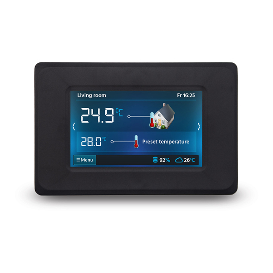
waste electrical electronic Main screen equipment (WEEE), according to which it is marked symbol crossed-out wheeled bin (like below), meaning that product is subjected to separate collection. Preset Responsibilities after finishing a period of temperature using product: dispose of the packaging and product at the end of their period of use in an appropriate recycling facility, ... -
Page 6: Operation Modes
9. Current level of fuel inside the feeder. After this mode is activated, its duration has 10. Current preset temperature inside the to be set within a range of 1÷60 h, in 1 h room. increments. After this period, the controller 11. -
Page 7: Antifreeze
8.3.8 Antifreeze set the comfort (day) or economic (night) The main controller works with a constant temperature with the use of button, preset temperature set in the following set the indicator “2” to an ending hour of menu: time zone with the use of <... -
Page 8: Settings
The alarm will not be deleted. For safety reasons, this can be done only via the main controller. 8.11 Settings Settings are available in the: Menu → Settings 8.11.1 Hysteresis This parameter defines hysteresis of room temperature. The main controller will start heating when the room temperature drops under the current preset temperature minus hysteresis. -
Page 9: Date
software version of the wireless room panels, Programmed schedule operates on the main controller and additional modules. the basis of internal memory of the wireless room panel and is not It is recommended to use the same software version for all connected deleted in absence of power supply. -
Page 10: Connection To The Main Controller
To do this, use the 12 VDC mains adapter, min. 0.5 A, which must be connected to the room panel connector with correct polarity. The room panel can be powered directly from the main controller socket, using a 2-wire cable, which should connected... -
Page 11: Pairing The Radio Module With The Wireless Room Panel
When connecting the transmission requires pairing with a wireless and power supply attention should room panel. be paid to the proper polarity of connection of D +, D- and GND, 12 Pairing from the main controller menu: VDC between the radio module and The pairing method is only available main controller. -
Page 12: Cooperation Of The Radio Module With Several Wireless Room Panels
Only one wireless room panel should be only one wireless room panel. In order to paired at this time, analogously as described check if it is possible to get full cooperation during pairing from the main controller menu with subsequent room panels, contact the level. -
Page 13: Main Controllers
11.5 Connecting the radio module to Connection of the module to the ecoMAX850P2, R2, D2: 1 - radio module, 2 – main controller. selected main controllers The electrical schemes of the radio module's electrical connections to the main controller's terminals are shown below. Connection of the module to the ecoMAX860P1, P2, D1, D2: 1 - radio module, 2 –... - Page 14 Connection with ecoMAX800P1, P2, D1, panel), only one room panel can be supplied D2 and ecoMAXX800R2, T2: directly from the controller module (terminal All 1,2,3 room panels require application of 31). Panels 2 and 3 have to be supplied by an additional power adapter 12 VDC / min.
- Page 15 If the main controller is equipped with TOUCH control panel (colored with a touch panel), only one room panel can be supplied directly from the controller module (terminal 40). Panels 2 and 3 have to be supplied by the additional power adapter 12 VDC / min. If the main controller is equipped with 0.5 A.
- Page 16 Connection with ecoMAX860P2, D2: Controller module can supply up to 2 colored TOUCH type panels simultaneously. If the main controller is equipped with a standard control panel (version with a knob), two room panels can be supplied directly from the controller module (socket G4). Third panel has to be supplied by the additional power adapter 12 VDC / min.
- Page 17 If the main controller is equipped with TOUCH control panel (colored with a touch panel), only one room panel can be supplied directly from the controller module (socket G4). Panels 2 and 3 have to be supplied by the additional power adapter 12 VDC / min. 0.5 A.
-
Page 18: Technical Data
13. Technical data Revision history: 5..12V DC – from the Wireless room panel external power supply power supply or socket of the main controller 5…12 VDC - directly Radio module power from main supply controller socket Current collected by the wireless room panel (at 0,15 A 12 VDC power supply) - Page 20 Wspólna 19, Ignatki 16-001 Kleosin Poland plum@plum.pl www.plum.pl...
Need help?
Do you have a question about the eSTER x80 and is the answer not in the manual?
Questions and answers