Table of Contents
Advertisement
Quick Links
Advertisement
Table of Contents

Related Manuals for National Instruments ECUTS-16000


Summary of Contents for National Instruments ECUTS-16000
- Page 1 ECUTS-16000/16001 User Manual March 2021 Information about the product and its features, technical and programming concepts, programming reference and syntax information, operating instructions, and more. In this document, the ECUTS-16000 and ECUTS-16001 are referred to collectively as ECUTS.
-
Page 2: Table Of Contents
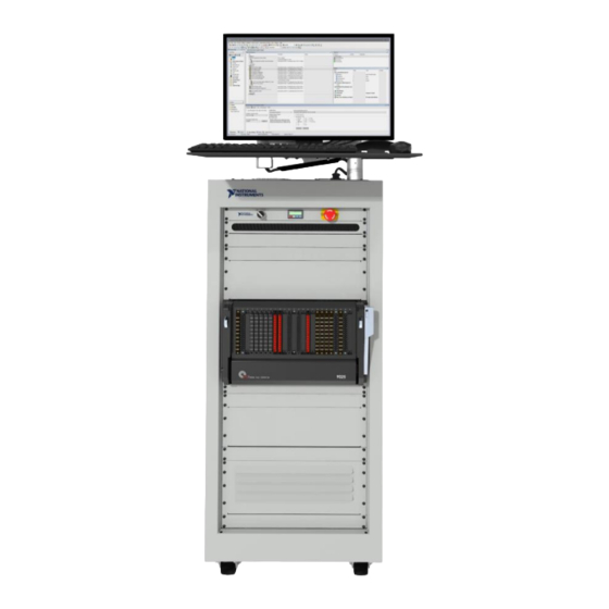
ECUTS-16000/16001 24U or 40U ECU Test System The ECUTS-16000 and ECUTS-16001 ECU Test System (ECUTS) are production-ready automotive test systems for automated testing of DUTs such as engine control units, transmission control units, and body controller modules. Content applies to all ECUTS models unless otherwise noted. -
Page 3: Before You Begin
Know the ECU Test System (ECUTS) basics and safety requirements before you perform any maintenance, test, or repair procedures. Visit ni.com/manuals to review the ECUTS-16000 Safety, Environmental, and Regulatory Information or ECUTS-16001 Safety, Environmental, and Regulatory Information document for safety information. - Page 4 RMX-4102, 36V 36 V, 12 A, programmable power supply device RMX-4102, 60V 60 V, 7 A, programmable power supply device Maximum input voltage in ECUTS-16000: 60 VDC, Measurement Category I. ECUTS-16000/16001 User Manual | © National Instruments Corporation | 3...
-
Page 5: Ecuts-16001 Components
Table 2. ECUTS-16000 Optional Hardware Components (Continued) Component Type Maximum Quantity Part Description Electronic Loads RMX-4002 4-Slot electronic load device mainframe 4 total RMX-4003 2-Channel, 100 W, electronic load device RMX-4005 1-Channel 350 W, electronic load device Peripheral Components 1 USB hub 7-Port USB 2.0 hub... - Page 6 SLSC-12251 16-Channel, 8 A, fault insertion unit Up to 12 (5 A max) SLSC-12252 8-Channel, 30 A, fault insertion unit Maximum input voltage in ECUTS-16001: 60 VDC, Measurement Category I. ECUTS-16000/16001 User Manual | © National Instruments Corporation | 5...
-
Page 7: Pxi
The IP address assigned to the electronic load instrumentation is 169.254.160.30. Power Distribution Unit The ECUTS-16000 contains one power distribution unit (PDU) that takes input power and distributes AC and DC power to the ECUTS-16000 components. The ECUTS-16001 contains two PDUs. One PDU takes input power and distributes AC and DC power to the ECUTS-16001 components, and the second PDU takes power and distributes AC power to the ECUTS-16001 components. -
Page 8: Field Diagnostic Tester
ECUTS instruments based on configurations defined in InstrumentStudio. InstrumentStudio is a software-based front panel application that allows you to perform interactive measurements on several different device types in a single program. InstrumentStudio is ECUTS-16000/16001 User Manual | © National Instruments Corporation | 7... -
Page 9: Code Modules
PS-16 SLSC Power Entry Power Distribution Panel Unit Multioutlet RMX Power Supplies Ethernet Switch RMX E-Load ECUTS -16000 Block Diagram Key Required Harware Block Power Hardware Populated as Required Signal Optional Hardware Block 8 | ni.com | ECUTS-16000/16001 User Manual... -
Page 10: Ecuts-16001 Block Diagram
ECUTS -16001 Block Diagram Key Required Harware Block Power Hardware Populated as Required Signal Optional Hardware Block ECUTS-16000 Component Locations Refer to the following figures to locate internal and external ECUTS-16000 components. ECUTS-16000/16001 User Manual | © National Instruments Corporation | 9... - Page 11 Figure 3. ECUTS-16000 Front Exterior 1. Emergency Power Off (EPO) Panel 3. Mass Interconnect 2. Cable Brush Panel 4. Exhaust Panel for Electronic Loads (Optional) 10 | ni.com | ECUTS-16000/16001 User Manual...
- Page 12 Figure 4. ECUTS-16000 Front Interior (Monitor Not Shown) 1. PXI Instrumentation 4. Power Distribution Unit (PDU) 2. PXI Controller 5. SLSC-12001 3. RMX Power Supplies (RMX-410x) 6. RMX Load Mainframe (RMX-4002) ECUTS-16000/16001 User Manual | © National Instruments Corporation | 11...
- Page 13 Figure 5. ECUTS-16000 Left Side Interior (Monitor Not Shown) 1. PXI-4112 Power Supplies (Optional) 2. USB-6363 Multifunction I/O Module (Optional) 12 | ni.com | ECUTS-16000/16001 User Manual...
- Page 14 Figure 6. ECUTS-16000 Right Side Interior (Monitor Not Shown) 1. NI-XNET Transceiver Cables (Optional) 2. PXI-4112 Power Supplies (Optional) ECUTS-16000/16001 User Manual | © National Instruments Corporation | 13...
- Page 15 1. Monitor 5. Panel Pneumatic Air Port 2. Monitor Arm and Keyboard Tray 6. Power Entry Panel (PEP) 3. Removable Rear Panel Door 7. Air Intake and Filter 4. Rear Cable Entry Brush Panel 14 | ni.com | ECUTS-16000/16001 User Manual...
-
Page 16: Ecuts-16001 Component Locations
4. Power Distribution Unit (PDU) 9. RMX-4002 Load Mainframe 5. SLSC Chassis 10. RMX-400x Electronic Load Devices ECUTS-16001 Component Locations Refer to the following figures to locate internal and external ECUTS-16001 components. ECUTS-16000/16001 User Manual | © National Instruments Corporation | 15... - Page 17 Figure 9. ECUTS-16001 Front Exterior 1. Monitor 4. Folding Keyboard and Mouse Tray 2. Cable Brush Panel 5. Mass Interconnect 3. Emergency Power Off (EPO) Button 16 | ni.com | ECUTS-16000/16001 User Manual...
- Page 18 1. Power Entry Panel (PEP) 5. SLSC Chassis 2. Seconday PXI Chassis (Optional) 6. Secondary PDU 3. Primary PXI Chassis 7. RMX Power Supplies 4. Primary Power Distribution Unit (PDU) ECUTS-16000/16001 User Manual | © National Instruments Corporation | 17...
- Page 19 Figure 11. ECUTS-16001 Left Side Interior 1. Secondary PXI Chassis (Optional) 3. PXI-4112 Power Supplies (Optional) 2. Primary PXI Chassis 4. Secondary Power Distribution Unit (PDU) 18 | ni.com | ECUTS-16000/16001 User Manual...
- Page 20 Figure 12. ECUTS-16001 Right Side Interior 1. Secondary PXI Chassis (Optional) 3. NI-XNET Transceiver Cables (Optional) 2. Primary PXI Chassis 4. USB-6363 Multifunctional I/O Module (Optional) ECUTS-16000/16001 User Manual | © National Instruments Corporation | 19...
- Page 21 6. SLSC Chassis 2. Secondary PXI Chassis (Optional) 7. Ethernet Switch 3. USB Hub 8. PS-17 4. Primary PXI Chassis 9. Secondary PDU 5. Primary Power Distribution Unit (PDU) 10. RMX Power Supplies 20 | ni.com | ECUTS-16000/16001 User Manual...
-
Page 22: Power States
The temperature controller on the EPO panel is reading a higher temperature than the programmed shutoff value. The system will power back on when the over-temperature condition clears. • The safety shutoff thermostats have detected unsafe air exit temperature. Refer to Powering on After Thermal Shutdown for more information. ECUTS-16000/16001 User Manual | © National Instruments Corporation | 21... -
Page 23: Using The Mass Interconnect
VPC Micro Power (50 pins) VPC QuadraPaddle (192 pins) VPC TriPaddle/Mini Power (16/16 pins) Mass Interconnect Pin Maps The following tables show the pin definitions for each slot type on the mass interconnect. 22 | ni.com | ECUTS-16000/16001 User Manual... - Page 24 Port 8 TRX+ Port 5 TRX- Port 6 TRX- Port 7 TRX- Port 8 TRX- Connect the interlock pins through dry contacts to their associated return pin to enable the respective subsystem. ECUTS-16000/16001 User Manual | © National Instruments Corporation | 23...
- Page 25 Figure 16. J2 Pin Map LOAD0+ SENSE0+ LOAD0- SENSE0- LOAD1+ SENSE1+ LOAD1- SENSE1- LOAD2+ SENSE2+ LOAD2- SENSE2- LOAD3+ SENSE3+ LOAD3- SENSE3- LOAD4+ SENSE4+ LOAD4- SENSE4- LOAD5+ SENSE5+ LOAD5- SENSE5- LOAD6+ SENSE6+ LOAD6- SENSE6- LOAD7+ SENSE7+ LOAD7- SENSE7- 24 | ni.com | ECUTS-16000/16001 User Manual...
- Page 26 CH75 CH77 COM71 COM73 COM76 COM78 CH71 CH73 CH76 CH78 COM74 CH74 COM79 CH79 AO0+ AO1+ AO2+ AO3+ AO0- AO1- AO2- AO3- AO4+ AO5+ AO6+ AO7+ AO4- AO5- AO6- AO7- ECUTS-16000/16001 User Manual | © National Instruments Corporation | 25...
- Page 27 Function HI SENSE LO SENSE See PXIe-2527 Topology Figures Below MUX_1 See PXIe-2527 Topology Figures Below MUX_2 AO3+ AO0+ AO1+ AO2+ AO0- AO1- AO2- AO3- AO4+ AO5+ AO6+ AO7+ AO4- AO5- AO6- AO7- 26 | ni.com | ECUTS-16000/16001 User Manual...
- Page 28 CH 26+ CH 28+ CH 30+ CH 24- CH 26- CH 28- CH 30- CH 25+ CH 27+ CH 29+ CH 31+ CH 25- CH 27- CH 29- CH 31- ECUTS-16000/16001 User Manual | © National Instruments Corporation | 27...
- Page 29 CH 7B- CH 8B+ CH 10B+ CH 12B+ CH 14B+ CH 8B- CH 10B- CH 12B- CH 14B- CH 9B+ CH 11B+ CH 13B+ CH 15B+ CH 9B- CH 11B- CH 13B- CH 15B- 28 | ni.com | ECUTS-16000/16001 User Manual...
- Page 30 A9:B9, A19:B19, A29:B29, and A39:B39. Row 1 is duplicated on C9:D9, C:19:D19, C29:D29, and C39:D39. Row 2 is duplicated on A14:B14, A24:B24, A34:B34, and A44:B44. Row 3 is duplicated on C14:D14, C24:D24, C34:D34, and C44:D44. ECUTS-16000/16001 User Manual | © National Instruments Corporation | 29...
- Page 31 A29:B29 and A39:B39. Row 5 is duplicated on A34:B34 and A44:B44. Row 6 is duplicated on A34:B34 and A44:B44. Row 7 is duplicated on C34:D34 and C44:D44. Columns 0-31 are duplicated from A5 through D23 and A25 through D43. 30 | ni.com | ECUTS-16000/16001 User Manual...
- Page 32 Matrix rows and columns are duplicated across the mass interconnect pinout as follows: Columns 0-15 are duplicated from A5 through D33, A15 through D23, A25 through D33, and A35 through D44. ECUTS-16000/16001 User Manual | © National Instruments Corporation | 31...
- Page 33 LOAD3 LOAD4 LOAD6 LOAD5 LOAD7 LOAD8 LOAD10 LOAD9 LOAD11 LOAD12 LOAD14 LOAD13 LOAD15 BUS A BUS B AO0+ AO1+ AO2+ AO3+ AO0- AO1- AO2- AO3- AO4+ AO5+ AO6+ AO7+ AO4- AO5- AO6- AO7- 32 | ni.com | ECUTS-16000/16001 User Manual...
- Page 34 Figure 26. J9, J10, J16 Pin Map Pneumatic Pneumatic DUT0 DUT1 DUT2 DUT3 DUT4 DUT5 DUT6 DUT7 LOAD0 LOAD1 LOAD2 LOAD3 LOAD4 LOAD5 LOAD6 LOAD7 ECUTS-16000/16001 User Manual | © National Instruments Corporation | 33...
- Page 35 FIU-2 LOAD10 FIU-3 LOAD10 FIU-1 LOAD11 FIU-2 LOAD11 FIU-3 LOAD11 FIU-1 LOAD12 FIU-2 LOAD12 FIU-3 LOAD12 FIU-1 LOAD13 FIU-2 LOAD13 FIU-3 LOAD13 FIU-1 LOAD14 FIU-2 LOAD14 FIU-3 LOAD14 FIU-1 LOAD15 FIU-2 LOAD15 FIU-3 LOAD15 34 | ni.com | ECUTS-16000/16001 User Manual...
- Page 36 DGND2 DGND3 P0.4 P0.5 P0.6 P0.7 P1.0 P1.1 P1.2 P1.3 DGND4 DGND5 DGND6 DGND7 P1.4 P1.5 P1.6 P1.7 P2.0 P2.1 P2.2 P2.3 DGND8 DGND9 DGND10 DGND11 P2.4 P2.5 P2.6 P2.7 ECUTS-16000/16001 User Manual | © National Instruments Corporation | 35...
- Page 37 AO23 AOGND20_21 AOGND24_25 AOGND22_23 AOGND26_27 AO24 AO25 AO26 AO27 AO28 AO29 AO30 AO31 AOGND28_29 AOGND_A_0 AOGND30_31 AOGND_A_1 DGNDP0.0_P0.1 DGNDP1.0_P1.1 P0.0 P0.1 P1.0 P1.1 P1.2 P1.3 DGNDP1.4_P1.5 DGND DGNDP1.2_P1.3 DGNDP1.6_P1.7 P1.4 P1.5 P1.6 P1.7 36 | ni.com | ECUTS-16000/16001 User Manual...
- Page 38 AI10- AI26- SHIELD (PXIe-4309) AI22+ AI14+ AI30+ A6 - AI22- AI14- AI30- AI3+ AI19+ AI11+ AI27+ AI3- AI19- AI11 - AI27- AI7+ AI23+ AI15+ AI31+ AI7 - AI23- AI15- AI31- ECUTS-16000/16001 User Manual | © National Instruments Corporation | 37...
- Page 39 Figure 31. J22 Pin Map when Populated with PXIe-5105 Oscilloscopes Function Function Function 12 V 24 V CHSGND DC Supplies 12 V COM 24 V COM J22_FGEN_1 PFI0 PFI1 J22_SCOPE_2 J22_SCOPE_1 J22_FGEN_2 PFI0 PFI1 PFI1 PFI1 J12-FIU1 J12-FIU2 J12-FIU3 J14-FIU1 J14-FIU2 J14-FIU3 38 | ni.com | ECUTS-16000/16001 User Manual...
- Page 40 DC Supplies 12 V COM 24 V COM J22_FGEN_1 PFI0 PFI1 J22_SCOPE_2 J22_FGEN_2 PFI0 J22_SCOPE_1 PFI1 PFI0 PFI0 PFI1 J12-FIU1 PFI2 J12-FIU2 PFI3 J12-FIU3 PFI1 J14-FIU1 PFI2 J14-FIU2 PFI3 J14-FIU3 ECUTS-16000/16001 User Manual | © National Instruments Corporation | 39...
- Page 41 Figure 33. J22 Pin Map when Populated with PXIe-5163 Oscilloscopes Function Function Function 12 V 24 V CHSGND DC Supplies 12 V COM 24 V COM J22_SCOPE_2 J22_SCOPE_1 PFI0 PFI0 CLKIN J12-FIU1 J12-FIU2 J12-FIU3 CLKIN J14-FIU1 J14-FIU2 J14-FIU3 40 | ni.com | ECUTS-16000/16001 User Manual...
- Page 42 Figure 35. J23 Pin Map CAN Port Pair CAN(x) LO CAN(x) SHIELD CAN(x+1) SHIELD CAN(x+1) LO CAN(x) HI CAN(x) VSUP CAN(x+1) VSUP CAN(x+1) HI CAN(x) COM CAN(x) COM CAN(x+1) COM CAN(x+1) COM ECUTS-16000/16001 User Manual | © National Instruments Corporation | 41...
- Page 43 Signal module, ITA, QuadraPaddle, 192 position, right angle contacts for custom PCB mounting (510 151 107 and 510 109 316) 510 108 126 TriPaddle signal, module, ITA, 96 position 510 108 125 Signal module, ITA, TriPaddle, 96 position with right angle contacts for custom PCB mounting 42 | ni.com | ECUTS-16000/16001 User Manual...
-
Page 44: Using Slsc Fault Insertion Units In Test Programs
You must follow all safety and site requirements and instructions to properly set up, configure, and use the ECUTS. Ensure the facility meets the following environmental, physical, and interface requirements before the ECUTS arrives. ECUTS-16000/16001 User Manual | © National Instruments Corporation | 43... -
Page 45: Ecuts-16000 Environmental, Physical, And Interface Requirements
16 A Pneumatic Air Pressure Rating Front and Back Frequency 100 PSI maximum 300 mm (12 in.) 50/60 Hz Maximum Branch Circuit 20 A Provide network connection. AC Inlet Type IEC 60320 C20 44 | ni.com | ECUTS-16000/16001 User Manual... -
Page 46: Ecuts-16001 Environmental, Physical, And Interface Requirements
Vous devez suivre les exigences de ventilation et de dissipation de puissance du ECUTS pour éviter tout risque thermique. Getting Started Receiving the ECUTS When the ECUTS shipping crate arrives at the facility, store the crate indoors in an area that meets the following conditions. ECUTS-16000/16001 User Manual | © National Instruments Corporation | 45... - Page 47 Unpacking the ECUTS-16000 Note The ECUTS-16000 shipping crate requires a clearance of at least 3.5 meters (11 ft) in front of the crate to lay out the crate ramp and roll the ECUTS-16000 out of the crate. Maximum weight of an ECUTS as configured by NI.
- Page 48 10. Unlock the brakes on the two visible caster wheels on the ECUTS-16000. 11. Slowly roll the ECUTS-16000 out of the crate and down the ramp using the green, horizontal straps. 12. Cut and remove the horizontal straps from the ECUTS-16000.
-
Page 49: Setting Up The Ecuts
Setting up the ECUTS ECUTS-16000 Installing the Monitor and Monitor Arm The ECUTS-16000 includes a monitor as well as a monitor arm with a keyboard tray. Use the following steps to install the monitor and monitor arm. Refer to the Ergomart TRS7000 Monitor Arm Installation Instructions to attach the monitor arm to the ECUTS-16000 mounting cylinder. -
Page 50: Basic Procedures
Complete the following troubleshooting steps if the ECUTS does not power on: • Ensure the system facility power is correct for the ECUTS. Refer to the ECUTS-16000 Test System Safety, Environmental, and Regulatory Information or ECUTS-16001 Test System Safety, Environmental, and Regulatory Information document for power requirements. -
Page 51: Creating A Backup Image
Clean the air intake filter using warm water with a mild soap solution, then air dry the filter to remove moisture. After verifying that the filter is dry, replace the filter in the test rack with the white side facing outwards. Replace the 4U air inlet panel. 50 | ni.com | ECUTS-16000/16001 User Manual... -
Page 52: Calibration
• Check if the PXI controller is properly seated inside the PXI chassis. • Check the PXI chassis LED indicators. • Check if the chassis power supply cable is connected. ECUTS-16000/16001 User Manual | © National Instruments Corporation | 51... -
Page 53: Repair
The AC power cords used in the ECUTS are specially designed for the ECUTS. Do not use these power cords in other electrical appliances. Note Repair procedures apply to both ECUTS-16000 and ECUTS-16001 models unless otherwise noted. Replacing PXI Instrumentation (ECUTS-16000) Replacing PXI Instrumentation Equipment •... - Page 54 With the ejector handle engaged, slide the replacement PXI instrument into the appropriate chassis slot. Lock the replacement PXI instrument in the chassis slot by pulling up on the ejector handle. Tighten the front panel mounting screws using the #2 Phillips screwdriver. ECUTS-16000/16001 User Manual | © National Instruments Corporation | 53...
-
Page 55: Replacing The Slsc Instrumentation
10. Connect all the cables to the front of the SLSC instrument. 11. Screw in the cable screws on the front of the SLSC instrument using the flathead screwdriver. 12. Close the rear cabinet door. 54 | ni.com | ECUTS-16000/16001 User Manual... -
Page 56: Replacing Rmx Power Supplies
Press the current encoder to reset the system. Flip the power switch to the off position and leave the RMX-410 power supply off for five seconds. Flip the power switch to the on position. ECUTS-16000/16001 User Manual | © National Instruments Corporation | 55... - Page 57 Click on the RMX power supply under Network Devices to show its configuration pane. Change the last to match the final number in the IP address of the RMX power supplies in the ECUTS-16000. For PPS_RMX_X example, IP address 169.254.130.21 will be PPS_RMX_1.
-
Page 58: Replacing The Pxi Chassis Rear Fans
Repeat steps c through h for each power supply. Replacing the PXI Chassis Rear Fans Note Use caution when removing the fan assembly to avoid damaging the internal wire harness. Equipment • #2 Phillips screwdriver ECUTS-16000/16001 User Manual | © National Instruments Corporation | 57... -
Page 59: Replacing The Pxi Chassis Side Fans
13. Pull the spring pin attached to the inside hinge of the rear cabinet down and secure the pin back to the test rack. 14. Close the rear cabinet door. Replacing the PXI Chassis Side Fans Note Use caution when removing the fan assembly to avoid damaging the internal wire harness. 58 | ni.com | ECUTS-16000/16001 User Manual... -
Page 60: Replacing The Test Rack Panel Fans
Loosen the set screw on the monitor arm using the hex driver. Lift the monitor arm out of the monitor mount. Remove the six screws on the fan plate using the #1 Phillips screwdriver. ECUTS-16000/16001 User Manual | © National Instruments Corporation | 59... -
Page 61: (Ecuts-16000) Replacing The Rmx Electronic Load Devices
15. Disconnect the interlock connector, ethernet jack connection, and AC power cable from the RMX load module. 16. Loosen the screw at the bottom of the RMX load module using the flathead screwdriver. 17. Slide the RMX load module out of the ECUTS-16000. 60 | ni.com | ECUTS-16000/16001 User Manual... - Page 62 18. Slide the replacement RMX load module into the ECUTS-16000. 19. Tighten the screw at the bottom of the RMX load module using the flathead screwdriver. 20. Connect the AC power cable, ethernet jack connection, and interlock connector to the RMX load module.
-
Page 63: Replacing The Usb-6363 Multifunction I/O Module
Disconnect the wires associated with the fan(s) that you want to replace from the terminal block. Insert the flathead screwdriver into the spring clamp activation slot to open the corresponding connector terminal. Pull the wire out of the connector terminal and remove the screwdriver. 62 | ni.com | ECUTS-16000/16001 User Manual... - Page 64 12. Pull the wire tight to prevent it from dangling beneath the tray. 13. Coil the wires and cable to secure them in place using the plastic cable ties and cable tie anchors from the fan kit. ECUTS-16000/16001 User Manual | © National Instruments Corporation | 63...
-
Page 65: Replacing Cables To The Mass Interconnect
19. Tighten the screws securing the mass interconnect to the test rack using the #2 Phillips screwdriver. 20. Replace the filler panels above and below the mass interconnect. 21. Screw in the four filler panel screws on each filler panel using the #2 Phillips screwdriver. 64 | ni.com | ECUTS-16000/16001 User Manual... -
Page 66: Replacing The Pxi-4112 Auxiliary Power Supplies
Zip ties Power off the ECUTS-16000. Verify there is not an ITA or FDT connected to the ECUTS-16000. Turn the two quarter-turn locks on the right panel of the test rack using the flathead screwdriver. Remove the right panel of the test rack. -
Page 67: Replacing The Pxi Chassis
While supporting the PXI chassis, carefully slide the PXI chassis out of the rear of the ECUTS-16000. While supporting the PXI chassis, carefully slide the replacement PXI chassis back into the rear of the ECUTS-16000. Replace the rear PXI chassis feet brackets using the #2 Phillips screwdriver. -
Page 68: Replacing The Slsc Chassis
16. Disconnect the power connector and ethernet cable from the rear of the SLSC chassis. 17. While supporting the SLSC chassis, remove the screws securing the SLSC chassis to the ECUTS-16000 using the #2 Phillips screwdriver. 18. Slide the chassis out the left side of the ECUTS-16000. - Page 69 29. Replace each filler panel above the mass interconnect. 30. Screw in the four filler panel screws on each filler panel using the #2 Phillips screwdriver. 31. Connect the cables to the SLSC instruments. 68 | ni.com | ECUTS-16000/16001 User Manual...
-
Page 70: Replacing The Pdu
Disconnect the VHDCI cables from the USB-6363. Disconnect the power cable from the USB-6363. Remove the two screws on the USB-6363 top retention bracket using the #2 Phillips screwdriver. Remove the USB-6363 from the test rack. ECUTS-16000/16001 User Manual | © National Instruments Corporation | 69... - Page 71 37. Screw in the four filler panel screws on each filler panel using the #2 Phillips screwdriver. (ECUTS-16001) Replacing the Lower PDU Equipment • #1 Phillips screwdriver • #2 Phillips screwdriver • Flathead screwdriver Power off the ECUTS-16001. 70 | ni.com | ECUTS-16000/16001 User Manual...
- Page 72 25. Connect the DC power cables to the PDU screw terminals using the flathead screwdriver. 26. Attach the TRC bracket to the right side of the rack using four screws and the #2 Phillips screwdriver. 27. Connect the transceivers to the PXIe-8510. ECUTS-16000/16001 User Manual | © National Instruments Corporation | 71...
-
Page 73: Replacing The Pep
17. Connect the facility AC power cable, ethernet cable, and USB cable to the PEP. 18. Attach the ground cable into the PEP ground lug. 19. Torque the ground cable nut to the PEP using the adjustable wrench to 1.29 N · m (11.5 lb · in.). 72 | ni.com | ECUTS-16000/16001 User Manual... -
Page 74: (Ecuts-16000) Replacing The Multioutlet
24. Tighten the set screw on the monitor arm using the hex driver. 25. Attach the cable gland and accompanying cables to the fan panel. 26. Connect the cables to the monitor. ECUTS-16000/16001 User Manual | © National Instruments Corporation | 73... -
Page 75: Replacing The Ethernet Switch
23. Place the monitor arm into the monitor mount. 24. Tighten the set screw on the monitor arm using the hex driver. 25. Attach the cable gland and accompanying cables to the fan panel. 26. Connect the cables to the monitor. 74 | ni.com | ECUTS-16000/16001 User Manual... -
Page 76: Replacing The Epo Panel
25. Replace the screws to the EPO panel using the #2 Phillips screwdriver. 26. Connect the cable labeled EDR to the PDU. 27. Replace the filler panels above the receiver using the #1 Phillips screwdriver. ECUTS-16000/16001 User Manual | © National Instruments Corporation | 75... - Page 77 26. Torque the ground cable nut to the PEP using the adjustable wrench to 1.29 N · m (11.5 lb · in.). 27. Plug the USB cables from the inside of the PEP to the PXI controller. 28. Plug in the keyboard and mouse to the PXI controller. 76 | ni.com | ECUTS-16000/16001 User Manual...
-
Page 78: Integrator Reference
240 V * 16 A = 3,840 W The following list indicates the maximum power that can be dissipated inside the ECUTS-16000 for a given ambient temperature with the lowest rated components installed. Additional power beyond the rated levels can be passed to components located externally to the ECUTS-16000. -
Page 79: Mechanical Stability And Loading
RMX-4002, if present, has a dedicated hot air exhaust panel on the front of the test rack. The following figure shows the distribution of hot and cold air inside the ECUTS-16000 and ECUTS-16001. 78 | ni.com | ECUTS-16000/16001 User Manual... -
Page 80: Configuring Pneumatics
Connect to the pneumatic output ports using 6 mm outer diameter tubing. Note Available pneumatic output ports on the mass interconnect are J9, J10, or J16 (if populated), in the pin 1 location. ECUTS-16000/16001 User Manual | © National Instruments Corporation | 79... -
Page 81: Ni Services
To submit a request for general technical support, complete the following steps. Collect your system information. Visit ni.com/support, and select Submit or Manage a Service Request. Use the Service Request Manager to request technical support. 80 | ni.com | ECUTS-16000/16001 User Manual... - Page 82 For patents covering NI products/technology, refer to the appropriate location: Help»Patents in your software, the file on your media, or the National Instruments Patent Notice at . You can find information about end-user license agreements (EULAs) and third-party legal notices patents.txt...
Need help?
Do you have a question about the ECUTS-16000 and is the answer not in the manual?
Questions and answers