
Related Manuals for ABB UniGear ZS1


Summary of Contents for ABB UniGear ZS1
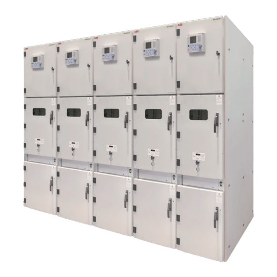
- Page 1 — INSTALLATION, OPERATION AND MAINTENANCE INSTRUCTION MANUAL UniGear ZS1 with a panel width of 500 mm • Safety • Reliability • Flexibility • Economy...
- Page 3 — Table of Contents Your safety first – at all times! 1. Summary 2. Technical data 3. Panel design and equipment 4. Dispatch and storage 5. Assembly of the switchgear at site 6. Operation of the switchgear 7. Commissioning 8. Maintenance 9.
- Page 4 U n i G e a r Z S 1 I N S T A L L A T I O N , O P E R A T I O N A N D M A I N T E N A N C E —...
- Page 5 Above and beyond this, the order- the insulation level must be taken into account related data from ABB must be taken into account. (please refer to the diagram in Figure 1) •...
- Page 6 ...4000 Branch connections rated current 630-1250 630-1250 1) Up to 4000 A if coupled with other UniGear ZS1 units. 2.2 Resistance to internal arc faults 2.3 Dimensions and weights The fault withstand capacity is 31.5 kA for 1 s. The switchgear units have been tested...
- Page 7 3 Panel design and equipment 3.1 Basic structure and variants The front of the panel is closed off by pressure The UniGear ZS1 panel uses insertion technology resistant doors. The cable and circuit-breaker for the incoming/outgoing feeder panel with a compartments have their own doors.
- Page 8 U n i G e a r Z S 1 I N S T A L L A T I O N , O P E R A T I O N A N D M A I N T E N A N C E 18.1 18.2 14.1 14.2 — Figure 2-1 Example of UniGear ZS1 unit Enclosure Earthing switch operating mechanism Pressure relief flap 14.1 Operating shaft for earthing switch Branch conductor 14.2...
- Page 9 P A N E L D E S I G N A N D E Q U I P M E N T 3.3 Panel compartments part is moved to the test/disconnected position. 3.3.1 Busbar compartment When the withdrawable part is in the test/ The main busbars are either flat or D-shaped and disconnected position inside the panel, are made of copper.
- Page 10 The withdrawable part and the panel are earthed 1) Withdrawable circuit-breaker parts: together by means of an earthing system in the The withdrawable part of the UniGear ZS1 panel. panel forms a complete module consisting of the vaccum circuit-breaker type VD4 (Fig. 5,...
- Page 11 P A N E L D E S I G N A N D E Q U I P M E N T 3.3.4 Cable connection compartment For more information regarding cable connections, Depending on individual operating requirements, please refer to chapter 5.10. the cable compartment can house up to three current transformers, fixed and withdrawable 3.3.5 Control cabinet...
- Page 12 U n i G e a r Z S 1 I N S T A L L A T I O N , O P E R A T I O N A N D M A I N T E N A N C E 3.4 Interlock/protection against incorrect 3.4.2 Interlocking doors operation...
- Page 13 P A N E L D E S I G N A N D E Q U I P M E N T Types of interlocks Standard safety interlocks (mandatory) Type Description Condition to be fulfilled Apparatus racking-in/out Apparatus in OFF position Apparatus closing Defined truck position Apparatus racking-in...
- Page 14 U n i G e a r Z S 1 I N S T A L L A T I O N , O P E R A T I O N A N D M A I N T E N A N C E —...
- Page 15 P A N E L D E S I G N A N D E Q U I P M E N T — Figure 11 Circuit-breaker compartment door locking device Note: It’s not suitable for floor rolling version. — Figure 12 Cable compartment door enabling device Pin ON Pin OFF...
- Page 16 U n i G e a r Z S 1 I N S T A L L A T I O N , O P E R A T I O N A N D M A I N T E N A N C E —...
- Page 17 P A N E L D E S I G N A N D E Q U I P M E N T 3.5 Circuit-breaker plug connector coding Coding: The control wiring plug connector coding allows (…) The corresponding coding designation for the withdrawable parts for switching devices the control wiring plug is given in brackets.
- Page 18 U n i G e a r Z S 1 I N S T A L L A T I O N , O P E R A T I O N A N D M A I N T E N A N C E —...
- Page 19 D I S P A T C H A N D S T O R A G E 4.5 Intermediate storage 4.6 Handling Optimum intermediate storage, where this is 4.6.1 Switchgear necessary, without any negative consequences The switchgear sections are usually fixed to depends on compliance with a number of minimum wooden pallets.
- Page 20 (Fig. 18). Use the eyebolts (1.5) and The apparatus can be handled by cranes, fork the ropes fitted with safety. After installation lift trucks or using the truck provided by ABB. of the panels, remove the eyebolts used for For each piece of apparatus follow the lifting.
- Page 21 (in parallel) with the front side of the switchgear! Warning • Do not use the service truck for any purpose other than handling ABB’s apparatus • Fix the circuit-breaker to the truck before moving it...
- Page 22 Carefully level the base irons both longitudinally compiled for the execution of a building, the and transversally over the entire length and binding data supplied by ABB for a particular correct the height by using strips with a suitable case must always be taken into account! thickness and a levelling instrument.
- Page 23 A S S E M B L Y O F T H E S W I T C H G E A R O N S I T E more than 2 mm over the entire length of the • Insert the plugs in the holes and put the individual frame panels on the traced perimeters of the units...
- Page 24 U n i G e a r Z S 1 I N S T A L L A T I O N , O P E R A T I O N A N D M A I N T E N A N C E nx FT View B —...
- Page 25 A S S E M B L Y O F T H E S W I T C H G E A R O N S I T E Power cables entry 6-mounting holes (36x20) Control cables entry — Figure 27 Base iron fixing system —...
- Page 26 U n i G e a r Z S 1 I N S T A L L A T I O N , O P E R A T I O N A N D M A I N T E N A N C E d 16 d 16 —...
- Page 27 3) The tightening torques are recommended for screws ISO 4014-4018 and ISO 4762 (tensile class 8.8). In case of usage of other types of screws contact please ABB for clarification. 4) Applicable only for fixing of subsidiary covers or terminal connections.
- Page 28 U n i G e a r Z S 1 I N S T A L L A T I O N , O P E R A T I O N A N D M A I N T E N A N C E 5.4 Procedure for setting-up the doors Closing of doors could be problematic in some cases.
- Page 29 A S S E M B L Y O F T H E S W I T C H G E A R O N S I T E Sliding part of the doors locking mechanism If guiding screws in open position of handle shall not be bended (could happen because of don’t reach end position, it’s necessary to wrong and rough closing operation).
- Page 30 U n i G e a r Z S 1 I N S T A L L A T I O N , O P E R A T I O N A N D M A I N T E N A N C E Before fixing the panels side by side (according 5.5 Installation of the bushing (if have) to the general drawings) bushings 29.x must be...
- Page 31 A S S E M B L Y O F T H E S W I T C H G E A R O N S I T E 5.6 Fixing of the panels The junction points where the panels should be Before fixing the panels side by side be fix are as follows: sure that the bushings are fixed according...
- Page 32 U n i G e a r Z S 1 I N S T A L L A T I O N , O P E R A T I O N A N D M A I N T E N A N C E 5.7 Installation of the busbars •...
- Page 33 A S S E M B L Y O F T H E S W I T C H G E A R O N S I T E Busbars for 12 kV units For 12 kV, the busbars are bare (without insulation) Busbars are made of copper and have a flat and without insulating covers up to 1250 A.
- Page 34 U n i G e a r Z S 1 I N S T A L L A T I O N , O P E R A T I O N A N D M A I N T E N A N C E nr.
- Page 35 A S S E M B L Y O F T H E S W I T C H G E A R O N S I T E Busbar compartment access After circuit-breaker has been withdrawn from the Access to the busbar compartment is possible panel, it is possible to remove the horizontal either from the top of the panel after dismounting partition.
- Page 36 U n i G e a r Z S 1 I N S T A L L A T I O N , O P E R A T I O N A N D M A I N T E N A N C E 5.8 Installation of the top-mounted boxes 5.8.1 Anti-ferroresonant resistor for voltage transformers open delta connection...
- Page 37 A S S E M B L Y O F T H E S W I T C H G E A R O N S I T E 5.9 Pressure relief ducts 5.9.1 Gas duct with outlet • The pressure relief duct is supplied dismantled Once the panels are bolted up, and busbars are in single components.
- Page 38 U n i G e a r Z S 1 I N S T A L L A T I O N , O P E R A T I O N A N D M A I N T E N A N C E 5.9.2 Gas duct with top chimneys In order to mount the gas duct with top chimneys please follow the appropriate instructions.
- Page 39 A S S E M B L Y O F T H E S W I T C H G E A R O N S I T E 5.10 Cable connection Connection of cables in typical panels: 5.10.1 Power cables Rated Rated Max.
- Page 40 U n i G e a r Z S 1 I N S T A L L A T I O N , O P E R A T I O N A N D M A I N T E N A N C E —...
- Page 41 A S S E M B L Y O F T H E S W I T C H G E A R O N S I T E 5.10.2 Control cables 5.12 Laying the ring circuits The control cables are conveyed into the panel The ring circuits are supplied - as a rolled-up through the control wiring duct on the left-hand bundle - in the control cabinet or in the accessories.
- Page 42 U n i G e a r Z S 1 I N S T A L L A T I O N , O P E R A T I O N A N D M A I N T E N A N C E —...
- Page 43 O P E R A T I O N O F T H E S W I T C H G E A R Important note: Withdrawal from the test/disconnected position The insertion and withdrawal of onto the service truck: circuit-breakers (and other withdrawable •...
- Page 44 U n i G e a r Z S 1 I N S T A L L A T I O N , O P E R A T I O N A N D M A I N T E N A N C E 6.1.2 Cicuit-breaker - type VD4 •...
- Page 45 O P E R A T I O N O F T H E S W I T C H G E A R 6.1.3 Withdrawable metering part Caution: If the operation is prevented, do not force the interlock and check that the Handling of the withdrawable metering or the voltage-transformer part in the metering panel operation sequence is correct.
- Page 46 U n i G e a r Z S 1 I N S T A L L A T I O N , O P E R A T I O N A N D M A I N T E N A N C E 6.2 Test procedures 6.2.2 Current and voltage tests 6.2.1 Testing the off-circuit condition...
- Page 47 C O M M I S S I O N I N G — 7 Commissioning 7.1 Preparatory work • For any other matters regarding operation of To prepare for commissioning, the following work the withdrawable circuit-breaker part and testing must be carried out prior to the connection of facilities for the withdrawable part, please see the high voltage power supply:...
- Page 48 It is lubrication, worn parts replacement and routine recommended that ABB service personnel perform tests execution. the servicing and repair work detailed below. Risk-based maintenance...
- Page 49 • The auxiliary limit switch for earthing switch ABB service department ON must be operated immediately after the toggle spring mechanism is precisely centered in the closing process and the automatic rapid...
- Page 50 Please refer to brochure 1VCP000427 - maintenance by ABB for more details on risk-based The following operating instructions must also maintenance. be followed, together with this instruction manual in the individual cases concerned.
- Page 51 M A I N T E N A N C E 8.8 Operating accessories Hand crank (to move the withdrawable part inside the panel) Operating lever (for earthing switch) Double bit key (for the central catch and screw type door catch) Hand crank (for the central catch or screw type door catch) —...
- Page 52 We the following methods of disposal: End of life of product Disposal can either be carried out thermally in an The ABB company is committed to complying with incineration plant or by storing on a waste site. the relevant legal and other requirements for environment protection according to the ISO 14001 standard.
- Page 53 — Note...
- Page 54 ABB Connect The digital assistant for all your electrification needs ABB Connect helps you to find product information and stay connected to the latest news and tools. It’s a digital assistant that enables customers to connect to the broadest range of electrification solutions in one place.
- Page 56 No.885, FangShanXiEr Road, Xiang'an District, Xiamen, Fujian, 361101 Tel: 0592 602 6033 Fax: 0592 603 0505 ABB China Customer Service Hot Line: TEL: 800-820-9696 / 400-820-9696 mail: cn-ep-hotline@abb.com www.abb.com © Copyright 2021 ABB. All rights reserved. Specifications subject to change without notice.