
Related Manuals for Huawei 3 U


Summary of Contents for Huawei 3 U
- Page 1 (IEC 19-inch & ETSI 21-inch Cabinet) 3 U Quick Installation Guide This document applies to the installation of the ATN 980C, NetEngine 8000 M8, PTN 6900-2-M8C, OptiX PTN 980, and OptiX PTN 980B. Issue:01...
-
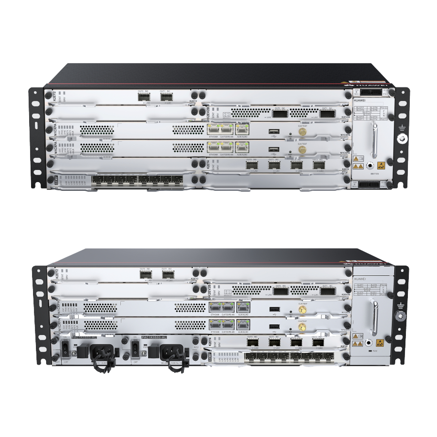
Page 2: Device Overview
Device Overview DC chassis AC chassis Packing list Insulation tape Corrugated pipe Quick Installation Guide Label cable tie ESD wrist strap Cable tie (300 x 3.6 mm) Signal cable label Panel screw (M6x12) Cable management frame Power cable label Serial cable Fiber binding tape Floating nut (M6) NOTE... -
Page 3: Safety Guidelines
Follow all the safety precautions and instructions provided by Huawei. The safety precautions outlined in this document are only requirements of Huawei and do not cover general safety regulations. Huawei is not liable for any consequence that results from violation of regulation spertaining to safe operations or safety codes pertaining to design, production, and equipment use. -
Page 4: Site Requirements
Site Requirements The device to be installed must be used indoors. To ensure normal operation and long service life of the device, the following requirements must be met: The device needs to be installed in a clean, dry, well ventilated, and temperature-controllable standard equipment room. -
Page 5: Cabinet Requirements
The device must be installed in an IEC 19-inch cabinet or an ETSI 21-inch cabinet. Huawei A63B cabinet is recommended. If customers choose to purchase cabinets by themselves, the cabinets must meet the following require- ments: 1. - Page 6 Installing a Device 5.1 Installing a Device in an IEC 19-Inch Cabinet Install floating nuts onto the cabinet. Floating nut Installation hole Install the cable management frame and power cable tray onto the device. Connect the PGND cable to the front or side face of the device. The side face is preferred.
- Page 7 Installing a Device Install the device into the cabinet. 5.2 Installing a Device in an ETSI 21-Inch Cabinet with Front Columns Install floating nuts onto the cabinet. Floating nut Installation hole Install the cable management frame and power cable tray onto the device.
- Page 8 Installing a Device Install conversion mounting ears on both sides of the device. Connect the PGND cable to the front or side face of the device. The side face is preferred. Install the device into the cabinet.
- Page 9 Installing a Device 5.3 Installing a Device in an ETSI 21-Inch Cabinet with Middle Columns Install floating nuts onto the cabinet. Floating nut Installation hole Install the cable management frame and power cable tray onto the device. Take out a pair of 19-inch mounting ears and install ETSI conversion mounting ears onto the 19-inch ones.
- Page 10 Installing a Device Install the 19-inch mounting ears and conversion mounting ears on the left and right sides of the device. Connect the PGND cable to the front or side face of the device. The side face is preferred. Install the device into the cabinet.
-
Page 11: Installing Components
Installing Components 6.1 Installing Boards Installing an interface board Installing a main control board CAUTION Wear ESD wrist straps or ESD gloves before installing or removing a board. Filler panels must be installed in vacant slots to ensure good electromagnetic compatibility and meet dust-proof and heat dissipation requirements. - Page 12 Installing Components 6.2 Installing Optical Modules NOTICE Huawei-certified optical modules need to be used. This is because the reliability of non-Huawei-certified optical modules cannot be ensured, and using such modules may affect service stability. Wear ESD wrist straps or ESD gloves before installing optical modules.
-
Page 13: Connecting Cables
Connecting Cables Common Cables PGND cable DC power cable Optical fiber AC power cable Shielded Ethernet 120-ohm 16 x E1 75-ohm 16 x E1 cable cable cable Routing Planning N OT E It is recommended that cables, including E1 cables, optical fibers, and Ethernet cables, be routed on the left side of the cabinet. - Page 14 Connecting Cables Cable layout in a scenario where a 3U device shares the same cabinet with other devices Installing a PGND Cable Installing DC Power Cables Check the fuse capacity of the external power supply. Device Model Recommended Fuse Capacity 320G/360G or lower: ≥...
- Page 15 Connecting Cables Take out the power connector Drag each power cable slightly from the packaging bag, and to check whether it is fastened. then strip each DC power cable If the cable is loose or its core for a length of 6 mm to 10 mm wires are exposed, disconnect according to the mark on the the cable, cut off the split part,...
- Page 16 Connecting Cables Installing an AC Power Cable Check the fuse capacity of the external power supply. Device Model Recommended Fuse Capacity ATN 980C ≥10A, ≤16A (For hierarchical power supplying protection,the current of the NetEngine 8000 M8/PTN 6900-2-M8C circuit breaker at the userside should be 10 A.) Installing an E1 Cable N OTE To avoid affecting right-hand board maintenance after cable routing, you...
- Page 17 Connecting Cables Installing an E1 cable with a negative 45-degree connector Installing an E1 cable with a positive 45-degree connector Installing Optical Fibers WARNING When performing operations such as installing or maintaining optical fibers, do not move your eyes close to or look into the optical fiber outlet without eye protection.
- Page 18 Connecting Cables N OTE The bending radius of a single-mode G.657A2 optical fiber is no less than 10 mm, and that of a multi-mode A1b optical fiber is no less than 30 mm. After laying out optical fibers, use binding straps to bind the fibers neatly without squeezing them.
- Page 19 Connecting Cables Installing Ethernet Cables N OTE The maximum number of shielded Ethernet cables supported by a flat-door cabinet is limited. For example, a 300 mm deep flat-door N63B/N63E cabi- net supports a maximum of six shielded Ethernet cables per layer of inter- face boards.
-
Page 20: Checking The Installation
Checking the Installation Check Before Power-on Check whether fixed optical attenuators have been added in accordance with corresponding configuration rules. Check whether the fuse capacity of the external power supply meets re- quirements. Check whether the external power supply voltage is normal. CAUTION If the power supply voltage does not meet requirements, do not power on the device. -
Page 21: Trademarks And Permissions
Copyright © Huawei Technologies Co., Ltd. 2021. All rights reserved. No part of this document may be reproduced or transmitted in any form or by any means without prior written consent of Huawei Technologies Co., Ltd. - Page 22 Appendix Inspecting and Cleaning Optical Fiber Connectors and Adapters Since the 50G optical module link uses the PAM4 encoding technology, there are higher requirements on the optical fiber and cable quality and the link is more sensitive to multipath reflection interference of signals.