
Related Manuals for Texmo Industries Taro Pumps Borewell


Summary of Contents for Texmo Industries Taro Pumps Borewell
- Page 1 Six Inch Borewell Submersible Pump Sets Instruction & Operating Manual OMBW004A 2020.01...
- Page 2 OMBW004A 2020.01...
-
Page 3: Table Of Contents
Table of Contents Introduction 2. Warranty information Complying with standards 4. Contents in the packing box 5. Information about your pump 6. Schematic drawings Key product specifications & features 8. Cross-section view Pre-installation requirements 10. Installation procedures 11. Basic troubleshooting 12. -
Page 4: Introduction
1. Introduction Thank you for choosing a quality product manufactured by Texmo Industries. We request you to read this manual carefully to ensure that the system you have purchased will be operated correctly. This manual is intended to provide you with information on your product and information on installation and operation. -
Page 5: Information About Your Pump
5. Information about your pump Taro Borewell Submersible pumpsets are manufactured using high quality raw materials and components and using state-of-the-art manufacturing facilities. Taro Borewell Submersible pumpsets will provide trouble- free performance if properly installed and maintained. Prior to installation, read this manual carefully and follow the instructions for installation and maintenance of our submersible pump set so as to ensure reliable operation and performance. -
Page 6: Schematic Drawings
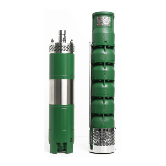
6. Schematic drawing View of a 6 inch Submersible Pump Set is shown below in Fig. 1: Fig. 1 View of 6 inch Submersible Pump Set Strainer Pump Motor Stage Bowl Cable Guard Strainer OMBW004A 2020.01... -
Page 7: Key Product Specifications & Features
Radial / Mixed Cable 3-core PVC Insulated Product Performance Specification Texmo Industries has a wide variety of 6 inch Borewell Submersibles to meet your requirements. Please consult our sales team / your nearest dealer to meet your specific requirements. OMBW004A 2020.01... - Page 8 Key features: Motor Designed for wide voltage operation The motor houses water lubricated journal and thrust bearings The stator winding is water cooled and is made from poly-wrapped copper wire Oil seal and sand guard is provided to prevent sand entry. High grade carbon thrust bearing enables reliable operation Winding overhang protector provided to ensure coil life Motor is filled with a mixture of pure clean water mixed with anti-corrosive liquid for improved...
- Page 9 Stainless steel shafts Cast Steel impeller in all series except TSS Cast Steel integral diffuser and diffuser housing in UH series Cast Steel diffuser in CI FG 200 diffuser housing for other series CI FG 200A integral diffuser and diffuser housing for R series Strainer To prevent ingress of pebbles into the intake during pumping, a Stainless Steel strainer is wrapped around the inlet bracket and cable box...
-
Page 10: Cross-Section View
8. Cross-section view Cross-section view of Three Phase 6 inch Submersible Motors is shown below in Fig. 2: Fig. 2 Cross-section view of 6 inch three-phase submersible motors PART NAME Motor Base Diaphragm cap Diaphragm Cap Nut Washer (Fibre) Washer (SS) Ball Locator Thrust Bearing Assembly "T"... - Page 11 Cross-section view of 6 inch Radial flow borewell submersible pumps is shown below in Fig. 3: Fig. 3 Cross-section view of 6 inch radial flow borewell submersible pumps PART NAME Inlet Bracket Strainer CSK Screw Inlet Sealing Ring Impeller Distance Sleeve Diffuser Housing Assy - Intermediate Diffuser...
- Page 12 Cross-section view of 6 inch mixed flow Borewell submersible pump is shown below in Fig. 4: Fig. 4 Cross-section view of 6 inch mixed flow borewell submersible pump PART NAME Inlet Bracket Strainer Pump Shaft CSK Screw Inlet Bowl Stage Bowl Intermediate Bowl Top Bowl Counter Thrust Collar...
- Page 13 Cross-section view of 6 inch radial flow stainless steel borewell submersible pump, TSS Series, is shown below in Fig. 5: Fig. 5 Cross-section view of 6 inch radial flow stainless steel borewell submersible pump PART NAME Inlet Bracket Strainer Hexagon Nut Bowl Stage Impeller NRV Seat...
- Page 14 Cross-section view of 6 inch radial flow ultra head borewell submersible, TRS UH Series, is shown below in Fig. 6: Fig. 6 Cross-section view of 6 inch radial flow ultra head borewell submersible pump PART NAME Inlet Bracket Strainer Sub Pump Shaft Distance Sleeve Inlet Thrust Ring Hex Head Bolt...
-
Page 15: Pre-Installation Requirements
9. Pre-installation requirements Arrangement for Installation Use the services of a professional and trained mechanic with experience in erecting borewell submersibles Ensure proper safety during installation Ensure availability of three-phase power General Installation Precautions Open packaging and note down the serial number and model for future reference Inspect the purchased pump for damage / leakage Ensure all fasteners are tightened properly Check the inside diameter of well casing to ensure that it is not smaller than the size of... - Page 16 Use trained professionals to install the submersible pump. Improper fitment can cause pump to fall into the bottom of the bore Caution Use a power supply cable that has sufficient rating and has been exclusively provided for the pump Warning Provide proper earthing as improper earthing can cause electrical shock Warning Use a megger to verify the Insulation resistance of the motor.
- Page 17 Operation Precautions Do not run the pump dry. It could lead to product damage Caution Switch OFF power supply and ensure that impeller completely stops before changing rotation or making any adjustments Warning Do not use this pump for pumping liquid exceeding 33 C as this may lead to product failure Caution...
-
Page 18: Installation Procedures
10. Installation procedure Please follow below procedure to install the pump and motor. The supply voltage should be within -15% to +6% of rated voltage. Water temperature for operation of the pump should not exceed 33 Failure to observe the precautions given above could cause the pump to Caution malfunction, which may lead to current leakage or electrical shock. - Page 19 The two threaded plugs are then re-assembled, ensuring the motor is encapsulated Dry the exterior of the motor and check thoroughly for water leakage If there is no leakage, the motor is now ready for coupling with the pump and then installation Place the motor key in the motor shaft keyway and then slide the coupling over the motor shaft until it rests on the sand guard Checking Insulation Resistance...
- Page 20 Procedure for joining and insulating the Proedure for joining and insulating the 3 core conductors cable joint for under-water cable Step 1: Soldering / knot the copper strands Step 6: Layer 1 - 1st layer of virgin rubber insulation Step 2: Layer 1 - 1st layer of virgin rubber insulation Step 7: Layer 2 - 1st layer of PVC insulation tape Step 3: Layer 2 - 1st layer of PVC insulation tape Step 8: Layer 3 - 2nd layer of PVC insulation tape...
- Page 21 Checking direction of rotation of Motor Hazardous voltage will cause death, serious injury, electrocution. All electrical work must be performed by an authorised electrician in compliance with local electrical equipment standards & internal wiring codes. Danger After waterproofing the joint connecting the submersible motor cable and supply cable, check if direction of rotation of the motor shaft matches the direction marked on the visible cable box top face The direction of rotation is counter-clockwise when viewed from the motor shaft end as marked...
- Page 22 Keep the submersible motor vertical Apply threading compound to internal thread on the delivery casing and external threaded portion of the short length delivery pipe to be fitted to the delivery casing Screw the short length of delivery pipe to the delivery casing Refer Fig.
- Page 23 Fit the supporting clamp to delivery pipe and suspend submersible pump from the chain block (Refer Fig. 10). Fig. 10 Typical tripod stand for lowering / lifting submersible pump sets Supporting Clamp Pipe Coupling Cable Clip Cable Submersible Pump Set Bore Well Casing Arrangement for installation Use the services of a professional and trained mechanic with experience in erecting borewell...
- Page 24 Electrical installation Check power supply voltage and frequency and compare with the product requirements specified on the name plate. Observe relevant EB regulations while giving power supply to the motor Use a single cable from control panel right up to submersible motor Ground the submersible motor Ensure the joint is waterproof as cable joint is submerged in water The cable must not be coiled if it is of extra length.
- Page 25 Cable lead wire connection to starter Direct online starter Cable Terminal Yellow Blue Star delta starter Cable 1 Terminal 1 Terminal 2 Yellow Blue OMBW004A 2020.01...
- Page 26 Cable Selection Refer TABLE 2 for the selection of cables from starter to Submersible Motor: Submersible Cable Selection Chart (For 415 V, 50 Hz Ac power supply) Cable size in Sq.mm Motor Rating Current 10.0 16.0 25.0 35.0 50.0 (Amps) Maximum Length of Cable in Metres 2.75 0.75...
- Page 27 Electrical wiring work All electrical work must be performed by an authorised electrician in compliance with local electrical equipment standards and internal wiring codes. Improper wiring can lead to current leakage, electrical shock, or fire. Provide a dedicated earth leakage circuit breaker, single phase preventer, dry run preventer and overload preventer for the submersible pump.
- Page 28 Do not use damaged cables, power plugs, or loose power outlets. Failure to observe this precaution could lead to electrical shock, short circuit or fire Caution Precautions during installation When installing the pump, be mindful of the pump’s centre of gravity and weight. If the pump is not suspended properly, the pump may fall and break, which may lead to injury Warning...
- Page 29 If a hose is used, route it as straight as possible. Excessive bending of hose could obstruct flow of water, reduce pumping volume, or clog the pump with sludge, thus disabling the pumping function Operate the pump upright. If there is likelihood of the pump drawing in excess mud / sludge, raise the pump by placing a concrete block under the pump If the pump draws in large amounts of mud, it could cause pump to wear prematurely and lead to malfunction, current leakage, and electrical shock.
-
Page 30: Basic Troubleshooting
11. Basic troubleshooting To prevent serious accidents, disconnect the power supply before inspecting pump. Warning Read this Operation manual thoroughly before requesting repair. Contact the dealer from whom this equipment was purchased. Servicing and troubleshooting must be handled by qualified persons with proper tools and equipment. Common faults, root cause for these, and suggested actions are provided in TABLE 3 below: Fault Possible causes... - Page 31 Fault Possible causes Suggested actions Available voltage is less Check for loose connections or contact EB authorities. If needed, replace the cable. Wrong direction of rotation For three phase, Interchange the supply connections of any two phases Increase in draw-down Lower the pumpset or wait for water level to rise Leakage in pipes Change pipes that have leakages...
- Page 32 Fault Possible causes Suggested actions Check line fuses / availability of three-phase supply Single phasing Check voltage Voltage too low Current Change rotor consumption in Defective rotor excess Change winding Defective motor winding Change worn-out bearings Damaged thrust bearing The discharge valve is closed Open the valve No water or too low water level in Lower the pump if head is within the specification...
- Page 33 OMBW004A 2020.01...
-
Page 34: Preventive Maintenance Checks
12. Preventive maintenance checks A definite schedule of preventive maintenance inspections should be established to avoid breakdown, serious damage, and / or extensive downtime. The schedule will depend on operating conditions and experience with similar equipment. Below checklist does not represent an exhaustive survey of maintenance steps necessary to ensure safe operation of the submersible pump. - Page 35 Maintenance precaution Disconnect power supply before starting maintenance or inspection of the pump to avoid electrical shock Warning If you find any damages or abnormalities, switch OFF the pump and report the problem to the dealer from whom the set was purchased Note NOTE: The manufacturer assumes no responsibility for damage or injury due to disassembly in the field.
-
Page 36: Do's And Don'ts
13. Do’s and don’ts Do’s Don’ts Prior to installation, check water level in submersible Do not erect pumpset at the very bottom of the bore motor. If required, top up with clear and clean drinking hole. Ensure at least 3 m clearance from bottom water. - Page 37 Do’s Don’ts If a plastic well casing is used in your installation, Do not perform frequent megger tests on the winding ground the metal well cap or well seal as the winding insulation can weaken When not in use, run the pump at least a few minutes Do not use oversized fuse wires as this can cause the a day motor winding to be damaged due to starter failure /...
-
Page 38: Important Safety Instructions
14. Important safety instructions Only qualified personnel should be involved for inspection, maintenance, and repairs. The successful and safe operation of such a product depends on proper handling, installation, and maintenance. It is suggested that in case of non-functioning of the product, the customer is requested to contact the dealer through whom the purchase was made. -
Page 39: Storage & Handling
15. Storage & handling Submersible pumps are supplied from factory in proper packing in which they should remain until they are ready to be installed The product should be stored in a closed, dry, and well-ventilated room Do not store the products under direct sunlight Handle pumps with care and do not expose product to unnecessary impact and shock During unpacking and prior to installation, care must be taken when handling the pump to ensure that misalignment does not occur due to bending... -
Page 40: Company Contact Information
16. Company contact information For most up to date information on Texmo Industries, please visit www.taropumps.com OMBW004A 2020.01... - Page 41 OMBW004A 2020.01...
- Page 42 P.B.No. 5303, 1800-102-8888 Mettupalayam Road, www.taropumps.com Coimbatore - 641 029, India info@taropumps.com OMBW004A 2020.01...
Need help?
Do you have a question about the Taro Pumps Borewell and is the answer not in the manual?
Questions and answers