Nokia NME-2A Series Installation Instructions Manual
Hide thumbs
Also See for NME-2A Series:
- Troubleshooting instructions (20 pages) ,
- Tuning instructions (14 pages)

Related Manuals for Nokia NME-2A Series


Summary of Contents for Nokia NME-2A Series
- Page 1 Programmes After Market Services (P.A.M.S.) Technical Documentations NME–2A SeriesTransceivers Installation Instructions Original 08/97...
-
Page 2: Table Of Contents
P.A.M.S. NME–2A Technical Documentation Installation Instructions Contents Page No Introduction ............Unpacking . - Page 3 P.A.M.S. NME–2A Technical Documentation Installation Instructions List of Figures Page No Figure 1. Equipment Listing Diagram ......Figure 2.
- Page 4 P.A.M.S. NME–2A Technical Documentation Installation Instructions [This page intentionally left blank] Original 08/97 Page 4...
-
Page 5: Introduction
P.A.M.S. NME–2A Technical Documentation Installation Instructions Introduction This installation guide has been prepared to provide the basic information necessary to install mobile phone. This guide is not intended to be definitive, because different types and models of vehicle will require different installation work. -
Page 6: Unpacking
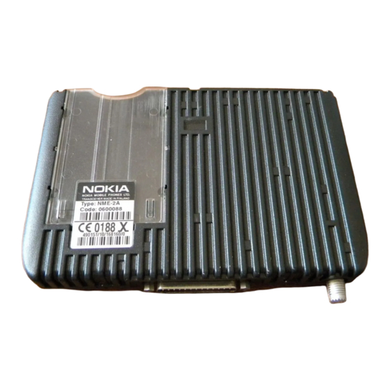
P.A.M.S. NME–2A Technical Documentation Installation Instructions Unpacking Carefully unpack the equipment and ensure that the following items are present. Figure 1. Equipment listing diagram Item/Product Name: Type: Remarks: Code: 1. Transceiver NME–2A 0600088 2. Handset HSE–6XA 0640086 3. Handsfree speaker HFM–10 (Molex type conn) 0692006 4. -
Page 7: Component Parts
P.A.M.S. NME–2A Technical Documentation Installation Instructions Component Parts Mounting Bracket MBE–2 The mounting bracket MBE–2 shall be installed using three screws. The bracket itself can to a certain degree compensate for unevenness of the mounting surface. However, should additional spacers be required, two different types are supplied with the bracket. -
Page 8: Handsfree Microphone Hfm-14 And Handsfree Speaker Hfs-10
P.A.M.S. NME–2A Technical Documentation Installation Instructions Handsfree Microphone HFM–14 and Handsfree Speaker HFS–10 The safest and easiest way to have call while driving is use the handsfree option. The system consist of two components, the microphone HFM–14 and loudspeaker HFS–10. The handsfree microphone can usually be installed on the drivers sunvisor or A–pillar. - Page 9 3 ft/1 m away from the handsfree unit speaker to avoid acoustic feedback. Ensure the microphone gain setting is in nokia position (default setting) with PCLocals or with handset by entering command xxxx and M.
-
Page 10: Power Distribution
P.A.M.S. NME–2A Technical Documentation Installation Instructions After drilling the hole for the antenna remember to clean the hole from the drilling swarf, so that surface is even. This is needed in order to ensure proper and reliable connection between the ground plane and the antenna. -
Page 11: Car Radio Muting (Xcrm)
P.A.M.S. NME–2A Technical Documentation Installation Instructions If the vehicle has +24 V electrical system (trucks, all–terrain vehicles , etc.), an external voltage reducer must be used. Since the properties of the reducer are critical, it is recommended to use a reducer supplied by the manufacturer. -
Page 12: Ignition Sense (Igns)
P.A.M.S. NME–2A Technical Documentation Installation Instructions When a relay is used, connect of series with the car radio main supply. A 200 mA fuse should be used to protect the XCRM output in event of a short circuit. Some radios have separate supplies for amplifiers and motors, and another for memory backup purposes. -
Page 13: Testing
P.A.M.S. NME–2A Technical Documentation Installation Instructions Bosch P/N 0–332–204–150 12 V, 30 A. SPDT 12 V d.c. CONTROLLED Supply for de- DEVICE, e.g. vice MOTOR TENNA From ANTC line (orange wire) Fuse 200 mA (not supplied) Figure 4. Connection – Power Antenna Control Testing Once installed, the equipment should be tested to ensure that it is operating satisfactorily and that the position of the units does not impair on... - Page 14 P.A.M.S. NME–2A Technical Documentation Installation Instructions [This page intentionally left blank] Original 08/97 Page 14...