KSB UPA Installation & Operating Manual
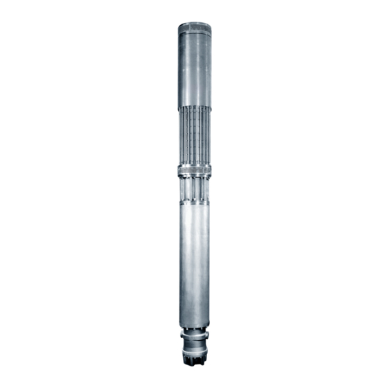
Submersible borehole pump
Hide thumbs
Also See for UPA:
- Installation & operating manual (64 pages) ,
- Manual (32 pages) ,
- Installation & operating manual (98 pages)

Related Manuals for KSB UPA


Summary of Contents for KSB UPA
- Page 1 Submersible Borehole Pump UPA, UPZ, BSX With Motors of 1000 V Supply Voltage and Above 50 Hz, 60 Hz Installation/Operating Manual...
- Page 2 All rights reserved. The contents provided herein must neither be distributed, copied, reproduced, edited or processed for any other purpose, nor otherwise transmitted, published or made available to a third party without the manufacturer's express written consent. Subject to technical modification without prior notice. © KSB SE & Co. KGaA, Frankenthal 01/12/2020...
-
Page 3: Table Of Contents
Installing the pump set in a suction, pressure or cooling shroud ........... 33 Installing the pump set in an angled position.................... 33 Information on electrical connection...................... 34 5.6.1 Operation with autotransformers and starting resistors .............. 34 5.6.2 Operation with soft starter ....................... 34 UPA, UPZ, BSX 3 of 68... - Page 4 Trouble-shooting.......................... 55 Related Documents .......................... 57 General drawings with list of components.................... 57 9.1.1 General assembly drawing of UPA 250 submersible borehole pump .......... 57 9.1.2 General assembly drawing: submersible motor V, X ............... 59 Mating dimensions for motors V, X, Z, E ...................... 61 Mating dimensions for motor T........................ 62...
-
Page 5: Glossary
A certificate of decontamination is enclosed by the customer when returning the product to the manufacturer to certify that the product has been properly drained to eliminate any environmental and health hazards arising from components in contact with the fluid handled. UPA, UPZ, BSX 5 of 68... -
Page 6: General
The order number and order item number uniquely identify the pump (set) and serve as identification for all further business processes. In the event of damage, immediately contact your nearest KSB service facility to maintain the right to claim under warranty. 1.2 Target group This operating manual is aimed at the target group of trained and qualified specialist technical personnel. -
Page 7: Symbols
In conjunction with one of the signal words this symbol indicates a hazard involving electrical voltage and identifies information about protection against electrical voltage. Machine damage In conjunction with the signal word CAUTION this symbol indicates a hazard for the machine and its functions. UPA, UPZ, BSX 7 of 68... -
Page 8: Safety
– Risk of cavitation damage ▪ Never exceed the permissible application and operating limits specified in the data sheet or product literature regarding pressure, temperature, etc. ▪ Observe all safety information and instructions in this manual. UPA, UPZ, BSX 8 of 68... -
Page 9: Personnel Qualification And Training
▪ If shutting down the pump does not increase potential risk, fit an emergency- stop control device in the immediate vicinity of the pump (set) during pump set installation. UPA, UPZ, BSX 9 of 68... -
Page 10: Safety Information For Maintenance, Inspection And Installation
Never operate the pump (set) outside the limits stated in the data sheet and in this manual. The warranty relating to the operating reliability and safety of the supplied pump (set) is only valid if the equipment is used in accordance with its intended use. UPA, UPZ, BSX 10 of 68... -
Page 11: Transport/Storage/Disposal
1. On transfer of goods, check each packaging unit for damage. 2. In the event of in-transit damage, assess the exact damage, document it and notify KSB or the supplying dealer and the insurer about the damage in writing immediately. - Page 12 ü The surface on which the pump set is to be positioned is solid and level. ü Securing means, e.g. timber wedges are on hand. 1. Gently place down the transport box. 2. Open the transport box. 3. Take out the power cable and place it down. UPA, UPZ, BSX 12 of 68...
-
Page 13: Pulling The Pump/Motor/Pump Set Upright
ü Suitable lifting equipment for the total weight has been selected and is on hand. 1. Fasten to a suitable lifting accessory, e.g. mounting plate. 2. Attach the lifting equipment, pull the pump/motor/pump set upright, and secure it against tipping over. UPA, UPZ, BSX 13 of 68... -
Page 14: Storage/Preservation
In a dry environment Protected against direct sunlight and heat Protected against dirt and dust Protected against freezing Protected against vermin Further information on storing the pump set after it has been in use (ð Section 7.5, Page 52) . UPA, UPZ, BSX 14 of 68... -
Page 15: Return To Supplier
Contact your local waste disposal partner for returns. If the used electrical or electronic equipment contains personal data, the operator is responsible for deleting it before the equipment is returned. UPA, UPZ, BSX 15 of 68... -
Page 16: Description Of The Pump (Set)
4.2 Product information as per Regulation No. 1907/2006 (REACH) For information as per chemicals Regulation (EC) No. 1907/2006 (REACH), see http:// www.ksb.com/reach. 4.3 Designation Submersible borehole pump Example: UPA 250C - 150 / 5b Table 4: Key to the designation Code Description Pump type Nominal size [mm] Design status Flow rate at best efficiency point [m³/h]... -
Page 17: Name Plate
4 Description of the Pump (Set) 4.4 Name plate KSB SE & Co. KGaA Johann-Klein-Straße 9 67227 Frankenthal Germany Serial No. 9971XXXX48-000100 Pump BRE 555/3 Qmin 300 L/MIN Hmax 108 M Qmax 1.170 L/MIN Hmin 69 M 879,6 L/MIN 92,7 M... - Page 18 ▪ Pump bearings lubricated by fluid handled; motor bearings lubricated by water fill ▪ Axial thrust is balanced by a tilting-pad thrust bearing in the motor (lower end) ▪ 1 intermediate bearing in the pump, depending on the pump size and the number of stages UPA, UPZ, BSX 18 of 68...
-
Page 19: Configuration And Function
4 Description of the Pump (Set) 4.6 Configuration and function Fig. 3: Sectional drawing, example of a UPA Design Pump and motor are connected by a rigid coupling. The stage casings are supported by straps or stud bolts. A suction strainer at the suction casing protects the pump from coarse particles in the fluid. -
Page 20: Dimensions And Weights
4.8 Dimensions and weights For dimensions and weights please refer to the data sheet of the pump (set). For motors UMA 300D, 14D only For UMA-S 150E, UMA-S 200D synchronous motors only UPA, UPZ, BSX 20 of 68... -
Page 21: Installation At Site
▷ Use additional supports for the transport holder to secure it against tilting. WARNING Incorrect handling of the power cable Personal injury and damage to property! ▷ Secure power cables against falling down. See cable manufacturer's documentation or DIN VDE 0298-3. UPA, UPZ, BSX 21 of 68... -
Page 22: Preparing The Installation
Is the temperature of the fluid to be handled below the specified maximum? If fluids liable to form deposits are handled, is temperature monitoring provided? Will the motor lead and the cable connector be completely immersed in the fluid to be handled? UPA, UPZ, BSX 22 of 68... -
Page 23: Checking The Installation Position
Never install horizontally a pump set which has been selected for vertical installation! Never install the pump set with the pump at the lowest point. UPA, UPZ, BSX 23 of 68... -
Page 24: Checking The Motor Fill
Unfilled or insufficiently filled motor Damage to the motor winding! ▷ Never install and run the motor without sufficient motor fill. ▷ Observe the information sticker on the motors and top up the motor fill as instructed. UPA, UPZ, BSX 24 of 68... - Page 25 ▷ Observe all legal regulations on the disposal. WARNING Screw plugs subjected to pressure When opening screw plugs, liquid might spurt out! ▷ Wear safety goggles and protective clothing, if required. ▷ Open the screw plug slowly. UPA, UPZ, BSX 25 of 68...
-
Page 26: Installing Water Storage Tanks
3. Fill the water storage tanks with the specified liquid fill until they overflow. 4. Close both water storage tanks with a screw plug with integrated vent valve (741) and joint ring (411.51). UPA, UPZ, BSX 26 of 68... -
Page 27: Preventing Backflow
See order documentation for any other type of use! See product literature of the riser used. Applies to pumps with lift check valve if no other measures to drain the riser have been taken. UPA, UPZ, BSX 27 of 68... -
Page 28: Measuring The Insulation Resistance
To meet this condition the cable connector must be completely submerged. Extension cables connected by KSB If agreed with KSB, the extension cable is supplied connected to the motor lead with a water-proof cable connector. ▪ Unless otherwise specified in the order documentation, KSB's extension cables are designed for: –... -
Page 29: Installing The Pump Set In Vertical Position
Otherwise, the electric cables could be affected by impermissibly high tensile stress. The measured value must be steady; a longer measurement period might be needed for larger cable cross- sections. UPA, UPZ, BSX 29 of 68... - Page 30 7. Fasten the second pair of supporting clamps to the second riser. 8. Use the lifting equipment to lower the second riser onto the first riser, and install it. Applies to flanged risers only UPA, UPZ, BSX 30 of 68...
-
Page 31: Attaching The Cable Ties
(5) together with the metal strap (4). Then attach the other end of the turnbuckle (1) to the metal strap (4). 4. Tighten the turnbuckle (1) with a screwdriver so that the power cable (3) cannot slip downwards by its own weight! UPA, UPZ, BSX 31 of 68... -
Page 32: Installing The Pump Set In A Horizontal Position
(See data sheet.) The required accessories depend on the weight and the overall length of the pump set. If agreed with KSB, the pump set is supplied with the accessories for the required installation type already fitted. -
Page 33: Installing The Pump Set In A Suction, Pressure Or Cooling Shroud
1. Some structural adjustments are required to install submersible borehole pumps in angled position. In such cases, always refer to the additional documentation supplied with the delivery. Permissible installation positions: UPA, UPZ, BSX 33 of 68... -
Page 34: Information On Electrical Connection
The pump set must not be installed in this position. 5.6 Information on electrical connection KSB's submersible borehole pumps > 1000 V are wired for DOL starting. During start- up and run-up the voltage must not fall below the value specified in the order documentation. -
Page 35: Operation On A Frequency Inverter
Motor size Minimum frequency f [Hz] For vertical installation For horizontal installation 2-pole motors 4-pole motors Maximum operating frequency Do not exceed the maximum operating frequency of 50 Hz/60 Hz respectively. Winding load Observe the following limits: UPA, UPZ, BSX 35 of 68... -
Page 36: Electrical Connection
1. Check the available mains voltage against the data on the name plate. 2. Terminate the cable ends properly with suitable cable terminations. If cable terminations are included in KSB's scope of supply, observe the separate installation instructions. 3. Check the starting method in the data sheet and select the corresponding circuit diagram. - Page 37 The six current-carrying conductors of the two parallel power cables are designated U1-1, V1-1, W1-1 and U1-2, V1-2, W1-2; the earth conductor is marked PE. (See circuit diagram.) The motors are wired in star (Y), and are fitted with two parallel power cables. UPA, UPZ, BSX 37 of 68...
-
Page 38: Recommended: Monitoring Equipment And Protective Equipment
▪ Semi-automatic or fully automatic dry running ▪ Wells with temporary low yields protection equipment (e.g. integrated in KSB's control unit UPA Control) Lightning/overvoltage A lightning protection device cannot offer protection ▪ Lightning protection against direct lightning strikes, however, it will... -
Page 39: Connecting The Temperature Monitoring Equipment
A2 = grey core A3 = blue core A4 = brown core Connection to the analysing device The sensor can be connected by 2-, 3- or 4-wire system. A1 A2 A3 A4 Pt 100 2-wire system UPA, UPZ, BSX 39 of 68... - Page 40 If the cut-out temperature t is reached, the motor must be tripped. It must Cut-out not be re-started until the malfunction has been remedied. Setting: Submersible motors with J2 winding (PE): t = 75 °C Cut-out UPA, UPZ, BSX 40 of 68...
-
Page 41: Commissioning/Start-Up/Shutdown
2. Start up the pump set. 3. Slowly open the shut-off element until the duty point is reached. NOTE When starting against an empty pipe, make sure that the air contained in the pipe can escape to atmosphere. UPA, UPZ, BSX 41 of 68... -
Page 42: Checking The Direction Of Rotation
3. Verify the read data against the data on the back-up name plate. ð If the values are almost identical, the direction of rotation is correct. ð If the read values are too low, the direction of rotation is incorrect. UPA, UPZ, BSX 42 of 68... -
Page 43: Operating Limits
A higher submergence may be required by the NPSH value specified in the order documentation or the value indicated in the following diagram. Q l/s Fig. 11: Minimum submergence depending on the flow rate UPA, UPZ, BSX 43 of 68... - Page 44 6 Commissioning/Start-up/Shutdown The values in the above mentioned diagram apply to submersible borehole pumps up to size UPA 350. For larger pump sets refer to the value X in the order documentation or the data sheet. Contact the manufacturer if required. NOTE The fluid level in the well is usually measured with a water level contact meter (well dipper).
- Page 45 ≤ 1165 ≤ 1180 ≤ 1200 ≤ 1230 ≤ 1270 2000 ≥ 0.2 ≤ 1900 ≤ 1910 ≤ 1920 ≤ 1940 ≤ 1970 ≥ 0.5 ≤ 1225 ≤ 1240 ≤ 1260 ≤ 1280 ≤ 1330 UPA, UPZ, BSX 45 of 68...
-
Page 46: Shutdown
1. Slowly close the shut-off element on the discharge side. 2. Switch off the motor immediately after closing the shut-off element. 3. Start up the pump set every 48 hours for approximately 5 minutes during prolonged shutdown periods. (ð Section 6.1, Page 41) UPA, UPZ, BSX 46 of 68... -
Page 47: Servicing/Maintenance
WARNING Persons could fall into unsecured wells/reservoirs/tanks Risk of personal injury! ▷ During installation work, take suitable precautions to protect anyone from falling into an open well/reservoir/tank. ▷ Suitably fence off the work area. UPA, UPZ, BSX 47 of 68... -
Page 48: Separating Pump And Motor
3. Remove the cable guard. Observe the minimum bending radius for the cable 4. Remove the suction strainer. 5. Remove the grub screw and the additional securing pin/bolt from the sleeve coupling at the motor end. See cable manufacturer's documentation or DIN VDE 0298-3. If any UPA, UPZ, BSX 48 of 68... -
Page 49: Motor Fill
/ antifreeze agent must not be filled with pure drinking water at a later stage. Pure drinking water can only be filled into motors which have not been filled before. UPA, UPZ, BSX 49 of 68... - Page 50 Mixing ratio / purpose ▪ The motors must only be filled with an antifreeze agent on a 1,2 propylene glycol basis which has been approved by KSB. ▪ The drinking water / antifreeze mixture supplied by the factory is intended for operation as well as storage, transport and preservation.
-
Page 51: Filling/Topping Up The Motor
2. Carefully lower the crane to slightly tilt the motor or pump set. 3. Monitor the screw plugs for escaping fluid. 4. If required, fit new sealing elements. UPA, UPZ, BSX 51 of 68... -
Page 52: Storage And Preservation
Pump sets / motors which have been operated must be overhauled. This must be performed by qualified specialist personnel, for example from a service workshop authorised by KSB. After the pump set / motor has been overhauled, fill the motor with drinking water/antifreeze mixture providing protection down to -15 °C, and store it. -
Page 53: Reassembling The Pump Set
8. Centre the pump, fit the sleeve coupling around the shaft stub, and lower the pump. 9. Fit nuts and assembly studs. Apply Loctite 242 and tighten the nuts by hand. UPA, UPZ, BSX 53 of 68... -
Page 54: Tightening Torques
731,0 548,0 343,0 409,0 984,0 736,0 M27x2 372,0 443,0 1060 797,0 466,0 554,0 1330 1000 M30x2 519,0 618,0 1480 1110 636,0 1820 1360 M33x2 700,0 2000 1500 812,0 2325 1740 M36x3 863,0 2465 1850 UPA, UPZ, BSX 54 of 68... -
Page 55: Trouble-Shooting
If problems occur that are not described in the following table, consultation with the KSB service is required. A Pump is running, but does not deliver B Insufficient flow rate... - Page 56 - Wrong fuse size Fit correct fuse size. ✘ ✘ ✘ Defective overcurrent relay Check and replace if necessary. - Motor winding not suitable for operating Replace the pump set. ✘ voltage available Contact KSB. UPA, UPZ, BSX 56 of 68...
-
Page 57: Related Documents
9 Related Documents 9 Related Documents 9.1 General drawings with list of components 9.1.1 General assembly drawing of UPA 250 submersible borehole pump 914.11 901.11 550.11 75--6 752.12 752.11 902.11 58--1 920.11 81--39 901.01 545.02 550.01 940.03 412.01 502.02 940.01 940.04... - Page 58 900.01 Bolt/screw Sleeve 901.01/.02/.11 Hexagon head bolt 525.01 Spacer sleeve 902.01/.02/.11 Stud 529.01/.02 Bearing sleeve 904.03 Grub screw Bush 914.11 Hexagon socket head cap screw 545.01/.02 Bearing bush 920.01/.11 550.01/.11 Disc Lock washer 940.01/.02/.03/.04/.05 UPA, UPZ, BSX 58 of 68...
-
Page 59: General Assembly Drawing: Submersible Motor V, X
412.52 412.51 160.53 903.51 920.52 411.51 902.51 116.51 920.51 900.51 160.52 550.51 59-12 901.51 160.51 932.51 232 108 Fig. 15: General assembly drawing, submersible motor V, X 81-11* earthing offset by 90°, 932.52, 550.54, 901.53 UPA, UPZ, BSX 59 of 68... - Page 60 901.51/.52/.53/.54 Hexagon head bolt 433.51 Mechanical seal 902.51/.52/.53 Stud 59-6 Ball 903.51 Screw plug 59-12 Diaphragm 914.51/.52 Hexagon socket head cap screw Bearing sleeve 920.51/.52/.53 Bearing bush 932.51/.52 Circlip 550.51/.52/.54/.55 Disc 940.51/.53 Spacer disc UPA, UPZ, BSX 60 of 68...
-
Page 61: Mating Dimensions For Motors V, X, Z, E
114 ± 0.1 ZBD ... 1.2 to 1.5 114 ± 0.1 ZMD ... 1.2 to 1.5 114 ± 0.1 EMD ... 1.2 to 1.5 114 ± 0.1 EBD ... 1.2 to 1.5 114 ± 0.1 UPA, UPZ, BSX 61 of 68... -
Page 62: Mating Dimensions For Motor T
9.3 Mating dimensions for motor T Fig. 18: Mating dimensions for motor T Observe the following dimensions: Table 24: Mating dimensions Motor type series Axial clearance Adjusting dimension A [mm] B [mm] 1.2 to 1.5 4.5 ± 0.1 UPA, UPZ, BSX 62 of 68... -
Page 63: Eu Declaration Of Conformity
10 EU Declaration of Conformity 10 EU Declaration of Conformity Manufacturer: KSB SE & Co. KGaA Johann-Klein-Straße 9 67227 Frankenthal (Germany) The manufacturer herewith declares that the product: UPA+TCD, VBD..EMD UPZ, BSX... BSF+TCD, VBD..EMD ▪ is in conformity with the provisions of the following Directives as amended from time to time: –... -
Page 64: Certificate Of Decontamination
We confirm that the above data and information are correct and complete and that dispatch is effected in accordance with the relevant legal provisions....................................Place, date and signature Address Company stamp Required field UPA, UPZ, BSX 64 of 68... -
Page 65: Index
Faults Causes and remedies 55 Frequency of starts 43 Impeller type 17 Intended use 8 Key to safety symbols/markings 7 Misuse 8 Order number 6 Other applicable documents 6 Product description 16 Return to supplier 15 Safety 8 Safety awareness 9 Scope of supply 19 Standstill period 43 UPA, UPZ, BSX 65 of 68... - Page 68 KSB SE & Co. KGaA Johann-Klein-Straße 9 • 67227 Frankenthal (Germany) Tel. +49 6233 86-0 www.ksb.com...
Need help?
Do you have a question about the UPA and is the answer not in the manual?
Questions and answers