Advertisement
Quick Links
Advertisement

Related Manuals for Van Der Valk ValkQuattro


Summary of Contents for Van Der Valk ValkQuattro
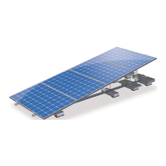
- Page 1 ValkQuattro Installation manual Van der Valk Solar Systems Solar Mounting Systems Version 02 | EN...
- Page 2 Page 03 Alu profiles Page 04 Push rods Page 05 Ballast Page 06 Placing panels Page 07 Placing panels Page 08 Cable clamp Page 09 Table of contents ValkQuattro Van der Valk Solar Systems Solar Mounting Systems Version 02 | EN...
- Page 3 Our terms and conditions shall apply to all our products and can be found on our website: www.valksolarsystems.nl. Van der Valk Solar Systems B.V. does not accept any liability for any direct and/or indirect consequences of any act (or omission) ensuing from the information in or the failure to observe the instruction provided in the project report and the installation manual and for possible incorrect results resulting from the use of this online calculation tool which was made available to you.
- Page 4 Required ballast | The Netherlands General The ValkQuattro® mounting system must be reinforced by means of tiles, which must be Note 1: The extra ballast must be equally divided over the ballast foundations. placed on the indicated ballast foundations. In three steps you can easily calculate the Note 2: The max.
- Page 5 Required ballast | Belgium General The ValkQuattro® mounting system must be reinforced by means of tiles, which must be Note 1: The extra ballast must be equally divided over the ballast foundations. placed on the indicated ballast foundations. In three steps you can easily calculate the Note 2: The max.
- Page 6 Required ballast | Germany General The ValkQuattro® mounting system must be reinforced by means of tiles, which must be Note 1: The extra ballast must be equally divided over the ballast foundations. placed on the indicated ballast foundations. In three steps you can easily calculate the Note 2: The max.
- Page 7 Required ballast | United Kingdom General The ValkQuattro® mounting system must be reinforced by means of tiles, which must be Note 1: The extra ballast must be equally divided over the ballast foundations placed on the indicated ballast foundations. In three steps you can easily calculate the Note 2: The max.
- Page 8 Required ballast | Ireland General The ValkQuattro® mounting system must be reinforced by means of tiles, which must be Note 1: The extra ballast must be equally divided over the ballast foundations. placed on the indicated ballast foundations. In three steps you can easily calculate the Note 2: The max.
- Page 9 Required ballast | Norway General The ValkQuattro® mounting system must be reinforced by means of tiles, which must be placed on the Note 1: The extra ballast must be equally divided over the ballast foundations. indicated ballast foundations. In three steps you can easily calculate the required ballast;...
- Page 10 Andøy Eigersund Bremanger near the Ålfotbreen 29 Hemsedal ӕ Solund Moskenes Hemsedal near Sogn og Fj. Sokndal ӕ Van der Valk Solar Systems Røst Bokn Selje Vågsøy Hol near Hordeland / Haugesund røy Sogn og Fjordane Klepp Skjerstad Municipality isn’t in the...
- Page 11 Required ballast | Sweden General The ValkQuattro® mounting system must be reinforced by means of tiles, which must be Note 1: The extra ballast must be equally divided over the ballast foundations placed on the indicated ballast foundations. In three steps you can easily calculate the Note 2: The max.
- Page 12 Required ballast | Finland General The ValkQuattro® mounting system must be reinforced by means of tiles, which must be Note 1: The extra ballast must be equally divided over the ballast foundations. placed on the indicated ballast foundations. In three steps you can easily calculate the Note 2: The max.
-
Page 13: Recommended Installation Tools
Recommended installation tools ValkQuattro Cordless drill Wrench 13 (for socket 13 and bit T-30) Socket 13 Torx bit T-30 Measuring tape... - Page 14 Required materials ValkQuattro A-frame connector (724420) Installation: Page 02 Roof carrier profile 2000mm (741802000) Alu. support (G13057703800000) Roof carrier profile 1500mm (741801600) Alu. support (G13057705550000) Installation: Page 01 Installation: Page 05 Alu. support (G13032208250000) Installation: Page 03 Alu. support (G13032208656565) Alu.
- Page 15 1900 Advised pitch measure 6700 (Based on sun angle 14,5 ) Panel leng 4089...
- Page 16 Attention! the 1600mm roof Front view carrier is placed in front of the 2000mm roof carrie 2nd to last hole Torque: 15 Nm ValkHint! 1) Place the mass blocks on the right locations before mounting the roof carriers. Detail A 8th hole from end roof carrier Torque: 15 Nm 16th hole from end roof carrier...
- Page 17 Detail A 5th hole from end roof carrier Detail A 18th hole from 15 Nm end roof carrier 2nd hole Mount the connector pieces to the roof carriers. Make sure they are placed as shown in the drawing. The groove on the bolt corresponds with the orientation of the bolt head!
- Page 18 Detail A 4th hole from end roof carrier Detail B 15 Nm 17th hole from end roof carrier 4th hole Mount the push rod to the roof carriers to connect the two rows. The groove on the bolt corresponds with the orientation of the bolt head!
- Page 19 Detail A.1 Detail A.2 The 2100mm profile is mounted in the middle, with a 1010mm profile on each end. M8x70 15 Nm ValkHint! Create the aluminium profile with the connector pieces/couplings first. Then mount the profile to the roof carrier.
- Page 20 Front view Detail A Diagonal rods Make sure the diagonal push rods are mounted in opposite directions (crossed) Mount the push rods betweeen the aluminium profile and the roof carrier.
- Page 21 Detail A 15 Nm 4 extra tiles 2 extra tiles 8 extra tiles 6 extra tiles For the required number of tiles check the ballast tables in front front of this manual.
- Page 22 Step 1 Step 3 Step 2 Take the end clamp out of it's slot for an easier The end clamp can only be turned clockwise, so assembly. make sure the end clamp is placed the right way. Step 4 Put the end clamp in the right slot to continue the Step 5 assembly.
- Page 23 Detail A 8 Nm Attention!! Do not forget to install the end clamps above the fourth panel! (same assembly as other end clamps, page 07.)
- Page 24 Mount cable clamp on the panel.
Need help?
Do you have a question about the ValkQuattro and is the answer not in the manual?
Questions and answers