Bose Companion 3 Series II Service Manual
Multimedia speaker system
Hide thumbs
Also See for Companion 3 Series II:
- Owner's manual (20 pages) ,
- Installation manual (20 pages) ,
- Service manual (16 pages)
Advertisement
Table of Contents
- 1 Table of Contents
- 2 Safety Information
- 3 Electrostatic Discharge Sensitive (ESDS) Device Handling
- 4 Specifications
- 5 Part List Notes
- 6 Bass Module Assembly Parts List
- 7 Amplifier Module Assembly Parts List
- 8 Packing Parts List
- 9 Electrical Parts List
- 10 Main PCB Assembly Parts List
- 11 Power Supply PCB Assembly Parts List
- 12 Disassembly Procedures
- 13 Test Procedures
- 14 Theory of Operation
- 15 Revision History
- Download this manual
®
Companion
3 Series II Multimedia
Speaker System
Product Description
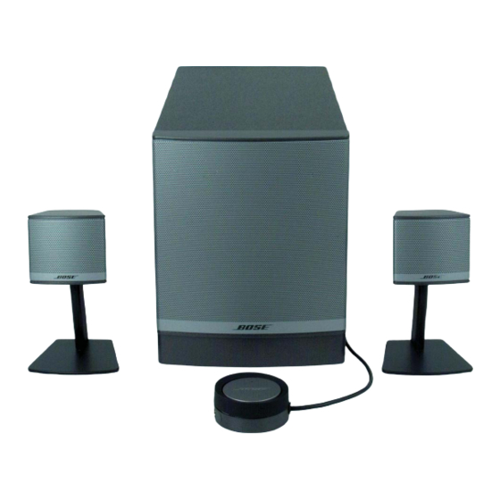
The Companion 3 series II multimedia speaker system is a stereo system designed to be used as a computer
sound system. It can be used with any analog audio source. It has a bass module with a 6.5 inch dual voice
coil woofer in a slot ported design. The two satellite speakers connect to the bass module and are mounted
to speaker stands. The speakers can be placed on a desk or other surface when removed from the stands. A
wired remote control pod is used to control volume and mute/un-mute functions. The system also has a
second input and a stereo headphone output on the control pod.
Service Manual
©2007 Bose Corporation
Reference Number 297700-SM Rev. 05
Electronic copy only
Advertisement
Table of Contents

Related Manuals for Bose Companion 3 Series II


Summary of Contents for Bose Companion 3 Series II
- Page 1 Product Description The Companion 3 series II multimedia speaker system is a stereo system designed to be used as a computer sound system. It can be used with any analog audio source. It has a bass module with a 6.5 inch dual voice coil woofer in a slot ported design.
-
Page 2: Table Of Contents
SERVICE CENTER OR OWNER OF THE BOSE PRODUCT, AND SHALL NOT BE REPRODUCED OR USED FOR ANY OTHER PURPOSE. Caution: The Companion 3 series II MultiMedia Speaker System contains no user serviceable parts. To prevent warranty infractions, refer servicing to warranty service centers or factory service. -
Page 3: Safety Information
Safety Information 1. Parts that have special safety characteristics are identified by the symbol on the schematics or by special notes on the parts list. Use only replacement parts that have critical characteristics recommended by the manufacturer. 2. Make leakage current or resistance measurements to determine that exposed parts are acceptably insulated from the supply circuit before returning the unit to the customer. -
Page 4: Specifications
Specifications Mechanical Dimensions: Bass Module: 8 5/8 “ H x 7 1/8” W x 14” D (21.8 x 18 x 35.56 cm) Satellite Speaker: 2 1/2” H x 2 3/4” W x 2 3/8” D (no stand) (6.14 x 6.86 x 6.03 cm) Control Pod: 2 1/2 “... -
Page 5: Part List Notes
Part List Notes 1. This part is not normally available from Customer Service. Approval from the Field Service Manager is required before ordering. 2. The individual parts on the PCBs are listed in the Electrical Part list. This part is critical for safety purposes. Failure to use a substitute replacement with the same safety characteristics as the recommended replacement part might create shock, fire and/or other hazards. -
Page 6: Bass Module Assembly Parts List
Bass Module Assembly Exploded View Item Description Part Number Qty. Note BASS MODULE, ASSY, US/CANADA, 120V (Electrofoil Logo) *300905-001 BASS MODULE, ASSY, EURO, 230V (Electrofoil Logo) *300905-003 BASS MODULE, ASSY, JAPAN, 100V (Electrofoil Logo) *300905-002 BASS MODULE, ASSY, US/CANADA, 120V (Padprint Logo) *303939-112 BASS MODULE, ASSY, EURO, 230V (Padprint Logo) *303939-122... -
Page 7: Amplifier Module Assembly Parts List
Amplifier Module Assembly Item Description Part Number Qty. Note PCB ASSY, MAIN 277574-001 BRACKET, METAL, IC 271859 HEATSINK, EXTRUDED, COMP 3 271856 CLIP, THERMAL, THERMISTOR 272964-001 HEAT SPREADER, ALUM 279844-001 SCREW, TAPP, 6-13x.625, PAN, XRC/S 172783-10 CONN, SWITCH, POWER, 3P 273115-001 PCB ASSY, PS, 120V, US *307872-011... -
Page 8: Packing Parts List
Packaging Part List Item Description Part Qty. Notes Number Number FEET, CLEAR SATELLITE 178321-04 FEET, RUBBER, BRACKET 260465 PACKING EPS, FILLER (includes both top and bottom filler) 300908-001 CONTROL POD, (NON-REPAIRABLE) 307874-002 CABLE, INPUT, 3.5MM, 6FT, BLK 271994-001 LINE CORD, 100V, BLK, JAPAN 264514-001 LINE CORD, 120V, BLK, US/CANADA 262814-001... -
Page 9: Electrical Parts List
ELECTRICAL PARTS LIST Main PCB Assembly Resistors Reference Description Part Number Note Designator R101 1.21K, 0805, 1/10W, 1% 133625-1211 R102 1.30K, 0805, 1/10W, 1% 133625-1301 R103 9.53K, 0805, 1/10W, 1% 133625-9531 R104 10.0K, 0805, 1/10W, 1% 133625-1002 R105 127K, 0805, 1/10W, 1% 133625-1273 R106 127K, 0805, 1/10W, 1%... - Page 10 ELECTRICAL PARTS LIST Main PCB Assembly Resistors Reference Description Part Number Note Designator R233 21.5K, 0805, 1/10W, 1% 133625-2152 R234 330 OHM, 0805, 1/10W, 1% 133625-3300 R235 6.81K, 0805, 1/10W, 1% 133625-6811 R236 17.4K, 0805, 1/10W, 1% 133625-1742 R237 1.62K, 0805, 1/10W, 1% 133625-1621 R238 2.00K, 0805, 1/10W, 1%...
- Page 11 ELECTRICAL PARTS LIST Main PCB Assembly Resistors Reference Description Part Number Note Designator R348 2.00K, 0805, 1/10W, 1% 133625-2001 R349 JUMPER, CHIP, 0805 133627 R350 JUMPER, CHIP, 0805 133627 R351 100OHM, 0805, 1/10W, 1% 133625-1000 R352 1.00K, 0805, 1/10W, 1% 133625-1001 R353 1.00K, 0805, 1/10W, 1%...
- Page 12 ELECTRICAL PARTS LIST Main PCB Assembly Resistors Reference Description Part Number Note Designator R969 JUMPER, CHIP, 0805 133627 R970 20.0K, 0805, 1/10W, 1% 133625-2002 R971 10.0K, 0805, 1/10W, 1% 133625-1002 R972 49.9K, 0805, 1/10W, 1% 133625-4992 R973 1.21K, 0805, 1/10W, 1% 133625-1211 R974 1.00K, 0805, 1/10W, 1%...
- Page 13 ELECTRICAL PARTS LIST Main PCB Assembly Capacitors Reference Description Part Number Note Designator C101 2.2uF, 1206, X7R, 10V, 20% 260361-2253 C102 .0068uF, BOX, 85C, 100V, 5% 137127-682 C103 .033uF, BOX, 85C, 63V, 5% 137127-333 C104 1000pF, 0805, COG, 50V, 5% 133622-102 C105 100 pF, 0805, COG, 50V, 5%...
- Page 14 ELECTRICAL PARTS LIST Main PCB Assembly Capacitors (continued) Reference Description Part Number Note Designator C307 1uF, EL, SMD, 105C, 50V, 20% 255071-1R0H C308 100 pF, 0805, COG, 50V, 5% 133622-101 C309 .015uF, 0805, X7R, 50V, 10% 133623-153 C310 100 pF, 0805, COG, 50V, 5% 133622-101 C311 10uF, EL, SMD, 105C, 25V, 20%...
- Page 15 ELECTRICAL PARTS LIST Main PCB Assembly Capacitors (continued) Reference Description Part Number Note Designator C401 10uF, EL, SMD, 105C, 25V, 20% 255071-100E C402 .01uF, 0805, X7R, 50V, 10% 133623-103 C403 .01uF, 0805, X7R, 50V, 10% 133623-103 C404 1000pF, 0805, COG, 50V, 5% 133622-102 C950 10uF, EL, SMD, 105C, 25V, 20%...
- Page 16 ELECTRICAL PARTS LIST Main PCB Assembly Diodes (continued) Reference Description Part Number Note Designator D401 DUAL, SOT-23, BAW56 180738 D402 DUAL, SOT-23, BAW56 180738 D403 SOT-23, BAV 99 147239 D951 SOT-23, BAV 70 147249 D952 SOT-23, BAV 99 147239 D954 DUAL, SOT-23, BAW56 180738 D955...
- Page 17 ELECTRICAL PARTS LIST Main PCB Assembly Miscellaneous Reference Description Part Number Note Designator J301 CONN, HEADER, 3 POS, .156 133220-03 J302 CONN, JACK PHONE, 3.5MM 269841-001 J305 CONN, HEADER, INLINE, PCB MNT, 4P 133220-04 J307 CONN, RCA, DUAL, PC MOUNT 272376-001 J308 CONN, MINI DIN, R/A, 9-PIN...
-
Page 18: Power Supply Pcb Assembly Parts List
ELECTRICAL PARTS LIST Power Supply PCB Assembly Resistors Reference Description Part Number Note Designator 10.0 OHM, 0805, 1/10W, 1% 133625-10R0 10.0 OHM, 0805, 1/10W, 1% 133625-10R0 10.0 OHM, 0805, 1/10W, 1% 133625-10R0 10.0 OHM, 0805, 1/10W, 1% 133625-10R0 2.00K, 0805, 1/10W, 1% 133625-2001 10.0 OHM, 0805, 1/10W, 1% 133625-10R0... - Page 19 ELECTRICAL PARTS LIST Power Supply PCB Assembly Diodes Reference Description Part Number Note Designator RECTIFIER, BRIDGE, 8A, 400V 260684-400 13V, ZEN, SOD-123, .5W, 5% 174265-5243 SOT-23, BAV 99 147239 Transistors Reference Description Part Number Note Designator BPLR, P, 40V, 200mA, SOT23 148596 BPLR, P, 40V, 200mA, SOT23 148596...
-
Page 20: Disassembly Procedures
Disassembly Procedures Bass Module 1. Module Assembly Removal 1.1 Remove the knob from the unit. 1.2 Peel back the label and remove it. Note: The label will become damaged once removed from the rear panel. A replacement label must be installed during reassembly. - Page 21 Disassembly Procedures Bass Module Cont. Speaker Connector 1.5 Disconnect the two connectors shown and remove the module assembly. Transformer Connector Power supply PCB 1.6 Disconnect the two connectors on the power supply PCB. 1.7 Remove the seven T-15 Torx screws shown, to remove the power supply PCB.
- Page 22 Disassembly Procedures Bass Module Cont. 2. Power Transformer Removal 2.1 Remove the module assembly, perform procedure 1. 2.2 Remove the bolt at the center of the power transformer. 2.3 Remove the transformer and shield-can from the bass box. 3. Woofer Removal 3.1 The Grille on the bass module is glued into place.
-
Page 23: Test Procedures
Test Procedures Test Equipment required: 1. Audio Signal Generator 2. Oscilloscope 3. Digital Multimeter Test Set up Connect the satellites to the output jacks on the bass module. Connect the control pod to the DIN jack on the bass module. Connect a signal generator to the audio input cable and connect the cable to the input jack on the bass module. - Page 24 Test Procedures 3. Bass Module Tone Control Test 3.1 Apply a 90 mVrms, 100 Hz signal to the input of the bass module. 3.2 Set the volume knob on the control pod to maximum (fully clockwise), and set the bass control to the center detent (flat) position.
- Page 25 Test Procedures 6. Control Pod Functional Test 6.1 With the system completely set up, turn on the system using the power switch located on the bass module. 6.2 Set the volume knob on the control pod to maximum (fully clockwise), and set the bass control to the center detent (flat) position.
-
Page 26: Theory Of Operation
Theory of Operation ® The Companion 3 Multimedia Speaker System is a 2.1 system designed to be used as a computer sound system. The electronics contain signal processing circuitry and the amplifiers for the woofer and satellites. A 120 volt AC input, 14 volt DC power supply powers the electronics. The power supply is located on a separate PC board. - Page 27 Theory of Operation Main Amplifier Board (continued) (refer the schematic diagram 276762) The signals coming into J308 (C7) are sent to sheet 3 of 3 (L_VOL and R_VOL). Three amplifiers in U201 (D8-4) are the equalizers for the right channel and U125, (A8-4) are the equalizers for the left channel.
- Page 28 Theory of Operation Main Amplifier Board (continued) (refer the schematic diagram 276762) The two satellite signals, and the bass signal are sent to the power Amp IC, U301 (C3). One channel of the power Amp IC is used for each satellite, and the bass signal uses two channels of the power chip to drive both of the woofer voice coils.
-
Page 29: Revision History
SERVICE MANUAL REVISION HISTORY Date Revision Description of Change Change Driven Pages Level Affected 9/06 Document released at Service Manual revision 00 Release 4/07 Added pad printed logo part Improvement of 5, 7 numbers for Bass module logo and Satellites New part number for power Improved power supply board –... - Page 30 SPECIFICATIONS AND FEATURES SUBJECT TO CHANGE WITHOUT NOTICE Bose Corporation The Mountain Framingham Massachusetts USA 01701 P/N 297700-SM Rev. 05 09/2007 (H): http://serviceops.bose.com...
- Page 31 Troubleshooting Tips Companion® 3 Series II Multimedia Speaker System Refer to the Companion® 3 Multimedia Speaker System service manuals, part number 297700 for schematics, PCB layouts and parts lists. Preventative Repair Measures Note: Perform the following on all units returned for repair. Product Check Action...
- Page 32 Troubleshooting Tips, continued Product Symptom Check Action No Audio Make sure the unit isn't At IC U301, place your positive stuck in standby probe on pin 22 and the negative probe on ground. Toggle the control pod between mute and Companion 3 standby by touching the top of the series II...
- Page 33 TP377 TP375 MMBT3906 TP330 MMBT3906 MMBT3906 Add Diode Q304 Q306 Q307 C311 R313-NV 10uF IABC3 D301 PGND C313 100uF IABC2 AGND IABC1 Date: 09/04 AGND FINS: 1569 Bose Corporation; The Mountain, Framingham, Ma. 01701-9168 Service documentation available online at http://serviceops.bose.com...
- Page 34 Location of C316, C317, C318 and C319 on Sheet 1 of SD280066 and SD271838 FINS: 2476, 2499 and 2619 FRACAS: 494 Date Issued: 10/05 Bose Corporation; The Mountain, Framingham, Ma. 01701-9168 Page 1 of 2 Service documentation available on-line at http://serviceops.bose.com...
- Page 35 Location of C316, C317, C318 and C319 on the bottom side of 271838-001 PCB FINS: 2476, 2499 and 2619 FRACAS: 494 Date Issued: 10/05 Bose Corporation; The Mountain, Framingham, Ma. 01701-9168 Page 2 of 2 Service documentation available on-line at http://serviceops.bose.com...
- Page 36 33000 µF, EL, AL, 25V, 4T 260693-3331E Euro/Japan 39000 µF, EL, AL, 25V 260693-3931E Ref Des Good Part Bad Part United Aishi Chemi-Con FINS: 2784 Date: 11/07 Bose Corporation; The Mountain, Framingham, Ma. 01701-9168 Service documentation available online at http://serviceops.bose.com...
Need help?
Do you have a question about the Companion 3 Series II and is the answer not in the manual?
Questions and answers