Table of Contents
Advertisement
Quick Links
Advertisement
Table of Contents

Related Manuals for NARDA L3HARRIS SMARTS II


Summary of Contents for NARDA L3HARRIS SMARTS II
- Page 1 SMARTS II Ultra-Wideband RF Radiation Area Monitor Operating Manual...
- Page 2 This Monitor should only be used after you have read this manual, understood how it operates and consulted with your company’s safety officer. Narda Safety Test Solutions GmbH Sandwiesenstrasse 7 72793 Pfullingen, Germany ® Names and logo are registered trademarks of Narda Safety Test Solutions GmbH and L3Harris Technologies, Inc.
-
Page 3: Table Of Contents
1 Introduction Contents Introduction ......................6 Measuring electromagnetic fields ..............6 About this monitor ..................... 6 Applications......................7 About this Operating Manual ................7 Usage of the brochure ..................7 Characters and symbols used ................7 Symbols and terms used in warnings ..............7 Structure of warnings ................... - Page 4 Contents Battery compartment ..................19 Input/output connector ..................20 Operation and installation ................. 22 Location ......................22 Options ......................22 Mounting the SMARTS II ..................23 Basic battery operation ...................23 To operate the SMARTS II from a battery without external connections .....23 External power supply operation ..............24 To operate the SMARTS II from an external low voltage supply ......24 Alarm threshold adjustment ................25 To change the alarm threshold ................25...
- Page 5 1 Introduction General Specifications..................35 Outline drawing ....................36 Declaration of conformity ................37 Declaration of origin ..................38 Ordering information ..................39 SMARTS II Sets part number ................39 SMARTS II...
-
Page 6: Introduction
1 Introduction Introduction This chapter contains a short introduction about measuring electromagnetic fields, about using the SMARTS II, and about the structure of this Operating Manual. Measuring electromagnetic fields About this monitor About this Operating Manual 1.1 Measuring electromagnetic fields In today’s world, many industries utilize equipment that generates electromagnetic fields. -
Page 7: Applications
1 Introduction entire hemisphere. They can even be mounted on a metallic wall. There is a SMARTS II model shaped to match most of the major safety standards. The SMARTS II operates from a 9-volt lithium Ultralife battery (U9VL) or an external +12 V to +24 V (Floating) supply. -
Page 8: Structure Of Warnings
1 Introduction The general danger symbol warns of risk of serious injury when used with the signal words CAUTION, WARNING, and DANGER. Follow all the instructions in order to avoid injuries or death. Indicates a danger that results in damage to or NOTICE destruction of the instrument. -
Page 9: Symbols And Marks Used In This Document
1 Introduction Symbols and marks used in this document Important instruction Indicates an instruction that must be followed to avoid danger. Requirement ✓ Indicates a requirement that must be met before the next instruction can be carried out, e.g. ✓ The instrument is switched off. Instruction ... -
Page 10: Preparing The Smarts Ii For Use
2 Preparing the SMARTS II for use Preparing the SMARTS II for use Intended use Unpacking Operation Electromagnetic fields Sensor area Power supply Batteries Instrument overview 2.1 Intended use Use the device only under the conditions and for the purposes for which it was designed. Pay particular attention to the information in the corresponding datasheet. -
Page 11: Unpacking
Do not operate a damaged device In the event of an incomplete delivery and damages to the monitor or accessories, please contact your Narda sales partner. You can find the Narda sales partner responsible for you on the Narda website at www.narda-sts.com. -
Page 12: Operation
The device is not ready for use until it has reached a temperature that is within the guaranteed operating range. For temperature ranges see the corresponding datasheet which can be downloaded at www.narda-sts.com/smarts-ii/. ⚠ WARNING Underestimation of the... -
Page 13: Electromagnetic Fields
2 Preparing the SMARTS II for use 2.4 Electromagnetic fields Strong electromagnetic fields Very strong electromagnetic fields are generated in the vicinity of certain radiation sources, which can lead to personal injuries or death in the case of endangered persons. Observe safety barriers and markings. -
Page 14: Sensor Area
2 Preparing the SMARTS II for use 2.5 Sensor area Metallic stickers in the sensor area can lead to measurement errors, in particular to an underestimation of the electromagnetic field strength. ⚠ WARNING Underestimation of the electromagnetic field Risk of personal injury or death to persons at risk ... -
Page 15: Mains Voltage, Condensation, Temperatures, Ventilation
2 Preparing the SMARTS II for use ⚠ WARNING Electrical voltages are present inside the power supply Risk of personal injury or death to persons at risk Do not use a damaged power supply Never open a power supply Mains voltage, condensation, temperatures, ventilation Incorrect mains voltage, condensation, high or low temperatures and... -
Page 16: Use And Replacement Of Batteries
2 Preparing the SMARTS II for use Do not solder anything to batteries. Use and replacement of batteries Improper replacement of batteries may result in injury and damage to the device or the batteries. Only operate the device with the permitted batteries (see 1.2 About this monitor or refer to the datasheet for information on the permissible types). -
Page 17: Instrument Overview
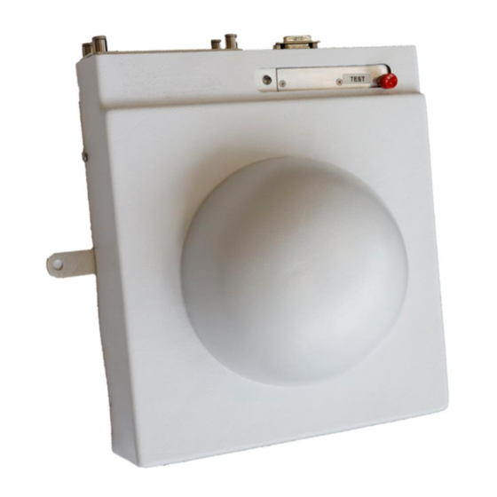
2 Preparing the SMARTS II for use Wipe up spilled electrolyte with an absorbent piece of cloth. However, protect the skin, eyes and respiratory tract from contact with the electrolyte. 2.8 Instrument overview Front view Top view LED indicator Access to Potentiometer Adjustment Battery 9-pin... -
Page 18: Operation Overview
3 Operation overview Operation overview This chapter describes important features and elements of the SMARTS Test button Alarm indications Sensor Battery compartment Input/output connector 3.1 Test button The TEST button provides a means to test most of the monitor circuitry. Briefly pressing the TEST button simulates an alarm condition. -
Page 19: Alarm Indication Overview
3 Operation overview Alarm indication overview Audible and visual alarm Condition Status signal indications Normal operation LED flashes every 40 sec. Alarm chirps and LED flashes every Low battery 40 sec. Continuous sound, LED flashes Test key depressed High every sec Continuous sound, LED flashes Alarm High... -
Page 20: Input/Output Connector
3 Operation overview Inside battery compartment: 3.5 Input/output connector All input and output connections are made via a single, 9-pin D- subminiature male connector located on the top side of the SMARTS II. A mating connector is supplied with the monitor. This input/output connector is used to provide connections for: ... - Page 21 3 Operation overview Pin nr Function N.O. (Normally open) Relay contact ENABLE/RECORDER (0/-1 V) Input/Output COM (Common) Relay contact STATUS (-4 V/+4 V) Input/Output N.C. (Normally closed) Relay contact +12 V to +24 V (shorted to 7), Floating supply see 4.5 External power supply operation p 24 +12 V to +24 V (shorted to 6), Floating supply see 4.5 External power supply operation p 24...
-
Page 22: Operation And Installation
4 Operation and installation Operation and installation Location Options Mounting the SMARTS II Basic battery operation External power supply Alarm threshold adjustment Zeroing procedure Test button Remote alarm indication 4.10 The ENABLE feature 4.11 Remote test 4.12 Low battery indication 4.1 Location The location where you mount the SMARTS II depends on many factors. -
Page 23: Mounting The Smarts Ii
4 Operation and installation Alarm Indications – either the internal audible and visual alarm indication and/or a remote indication can be used. External alarms require a cable connection. Remote Test – available with a cable connection. Enable – alarm operation can be inhibited when people are not present during high power operation. -
Page 24: External Power Supply Operation
4 Operation and installation 5. Put the battery in place into the compartment. 6. Replace the battery-compartment cover and finger-tighten the four captive screws. It is important that the screws are tightened sufficiently so that the cover slightly compresses the EMI gasket. 7. -
Page 25: Alarm Threshold Adjustment
4 Operation and installation 8. Mount the monitor in the desired location using the holes in the mounting brackets and screws suitable for the surface that the monitor is being mounted on. Connector, D-subminiature male: ⚠ CAUTION Underestimation of the electromagnetic field Risk of personal injury and malfunction of the device... -
Page 26: Zeroing Procedure
4 Operation and installation Alarm Threshold 10 % 25 % 35 % 50 % 3. Replace the battery compartment cover and finger-tighten the four captive screws. It is important that the screws are tightened sufficiently so that the cover slightly compresses the EMI gasket. 4.7 Zeroing procedure It is possible to check the Zero setting and adjust it if necessary. -
Page 27: Test Button
4 Operation and installation 4.8 Test button See 3.1 Test button 4.9 Remote alarm indication When the SMARTS II detects radiation at its preset alarm threshold or higher, an electronic signal is provided at the STATUS line (pin 4) to activated various user-supplied remote circuitry Alarm status can be detected remotely by using the STATUS signal, the RECORDER output level, and/or the STATUS relay (SPDT) -
Page 28: The Enable Feature
4 Operation and installation 4.10 The ENABLE feature To avoid the alarm indication being on constantly, the ENABLE input can be used in situations where the standard operating procedure produces RF fields above the alarm threshold and exposure to people is possible. -
Page 29: Determining Location
5 Determining location Determining location This chapter include points to consider when choosing the SMARTS II monitoring location. Overview Factors determining area coverage Preferred location Alternate locations 5.1 Overview The factors that determine when a SMARTS II monitor will activate its alarms include: ... -
Page 30: Factors Determining Area Coverage
5 Determining location 5.2 Factors determining area coverage Energy sources, either purposeful emitters such as antennas, or unintentional emitters such as waveguide leaks, can be omnidirectional or focused in one direction. Field strength (power density expressed in mW/cm2 or W/m2) drops off rapidly with distance from the source. In the far field, field strength follows the inverse square law, i.e., at twice the distance there is one quarter the field strength. - Page 31 5 Determining location Mounting a SMARTS II further from the energy source than people will be. Although it is possible to use a SMARTS II in this application, it is risky. In order to use this approach successfully, it is important to calculate the relative energy levels that the monitor and people will be exposed to based on the distance from the energy source to the monitor and the distance from the source.
-
Page 32: Maintenance
Unauthorized or improper repairs or modifications Unauthorized or improper repairs or modifications can impair the accuracy and function of the device. Repairs should only be carried out by approved Narda Service Centers. Otherwise, any warranty claims shall lapse. Modifications to the device are not permitted. Modifications void any warranty claims. -
Page 33: Proper Disposal (Eu Only)
6.3 Proper disposal (EU only) Disposal of the unit This Narda product is a high quality device that can be expected to last a long time. Nevertheless, this device will also reach the end of its service life at some point. Please note that electrical devices must be disposed of properly. -
Page 34: Specifications
Specifications Monitor Specifications General Specifications Outline drawing Declaration of conformity Declaration of origin SMARTS II... -
Page 35: Monitor Specifications
7 Specifications 7.1 Monitor Specifications Parameter Specification Frequency Range (nom.) 2 MHz to 100 GHz Field Measured Electric Field, Sensor Design Hemispherical coverage, Diode and Thermocouple array Frequency Sensitivity +6.0 / -3.0 dB (100 kHz to 2.3 GHz) +4.5 / -2.5 dB (2.3 to 30 GHz) +2.5 / -6.0 dB (30 to 50 GHz) +2.5 / -6.0 dB (50 to 100 GHz, Typical) Test Frequencies... -
Page 36: Outline Drawing
7.3 Outline drawing SMARTS II... -
Page 37: Declaration Of Conformity
7 Specifications 7.4 Declaration of conformity SMARTS II... -
Page 38: Declaration Of Origin
7.5 Declaration of origin Country of Origin Germany SMARTS II... -
Page 39: Ordering Information
8 Ordering information Ordering information SMARTS II Sets part number 8.1 SMARTS II Sets part number SMARTS II area monitor sets Part number SMARTS II Set, FCC 1997 Occupational/Controlled 2688/101 2688/104 SMARTS II Set, ICNIRP 1998 Occupational SMARTS II Set, IEEE C95.1-2019 Restricted environm. 2688/105 Each set includes: ›... - Page 40 Narda Safety Test Solutions GmbH Sandwiesenstrasse 7 72793 Pfullingen, Germany Phone +49 7121 97 32 0 info.narda-de@L3Harris.com L3Harris Narda-STS North America Representative Office 435 Moreland Road Hauppauge, NY11788, USA Phone +1 631 231 1700 NardaSTS@L3Harris.com Narda Safety Test Solutions S.r.l.
Need help?
Do you have a question about the L3HARRIS SMARTS II and is the answer not in the manual?
Questions and answers