NARDA SRM-3006 Operating Manual
Selective radiation meter
Hide thumbs
Also See for SRM-3006:
- Command reference manual (166 pages) ,
- Manual (25 pages) ,
- Handling instructions manual (142 pages)
Table of Contents

Related Manuals for NARDA SRM-3006


Summary of Contents for NARDA SRM-3006
- Page 1 SRM-3006 Selective Radiation Meter Operating Manual...
- Page 2 Narda Safety Test Solutions GmbH Sandwiesenstraße 7 72793 Pfullingen, Germany © 2010 Order no.: 3006/98.21 Issue: 03/04.2010, A ... Previous issues: 02/11.2009, A ... Subject to change. Our normal terms of warranty and delivery apply. Printed in Germany...
-
Page 3: Table Of Contents
Cables ......... . . 7 SRM-3006 as a laboratory device ..... . 8 1.3.1... - Page 4 3.4.4 Fitting a Narda antenna on a tripod ....33 Operation and Basic Settings ......39 Controls .
- Page 5 Deleting setups ........67 5.5.5 Changing the switch on behavior..... . 68 Narda SRM-3006...
- Page 6 Saving a setup ........92 SRM-3006...
- Page 7 The Marker function (Marker) ..... . . 114 The Zoom function (Zoom) ......114 Narda SRM-3006...
- Page 8 Individual results ....... . . 138 11.3.2 Total result (Total) ....... . 138 SRM-3006 Narda...
- Page 9 Time Controlled Storing of measured values... . 163 13.4.3 Changing the comment modes ..... . 165 Narda SRM-3006...
- Page 10 17.1 SRM-3006........182 17.1.1...
- Page 11 Ordering Information ........213 19.1 SRM-3006 sets ........214 19.2 Antennas .
- Page 12 Contents SRM-3006 Narda...
-
Page 13: Introduction
Introduction This chapter contains basic information on measuring electromagnetic fields, on using the SRM-3006, and on how this manual is laid out. About this device (page 2) SRM-3006 as a field strength meter (page 4) SRM-3006 as a laboratory device (page 8) -
Page 14: About This Device
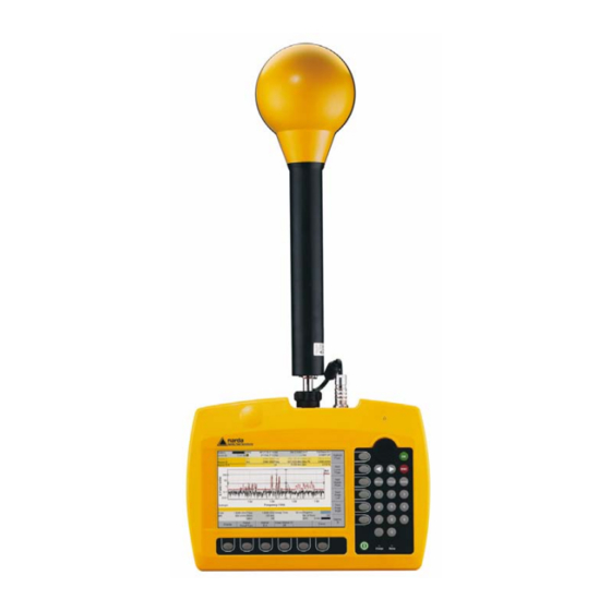
In unknown field environments such as those around so-called shared sites, where several providers of mobile telephone services share a common antenna site, the SRM-3006 displays the total field level as well as the contributions made by the individual services, either as absolute values or as a percentage of the permitted limit level. - Page 15 1 Introduction Figure 1: SRM-3006 in on-site use Narda SRM-3006...
-
Page 16: Srm-3006 As A Field Strength Meter
Basic Unit but to place it some distance away and use a cable to connect it. A 1.5 m long cable is included in all SRM-3006 field strength measuring system sets including antenna that are offered by Narda Safety Test Solutions. -
Page 17: Basic Unit
1 Introduction 1.2.1 Basic unit The SRM-3006 is a field meter that has been specially designed for use outdoors and in difficult to reach or uncomfortable measurement locations. The functions of the device have therefore been tailored to ensure ease of handling in practical situations. - Page 18 (but modification from 75 MHz to 27 MHz will be charged for). You can get further information from one of our Sales Partners in your locality or from our homepage www.narda-sts.de under Service. SRM-3006...
-
Page 19: Cables
Basic Unit by a multi-pin connector, and transfers the antenna parameters (type, serial number, calibration date, list of attenuation factors) to the Basic Unit so that the SRM-3006 can recognize and use this data. This cable also allows the SRM-3006 to control... -
Page 20: Srm-3006 As A Laboratory Device
N connector. The SRM-3006 set includes a 1.5 m long cable. A 5 m long cable can be ordered as an optional accessory (see Ordering Information on page 213). -
Page 21: Basic Unit
1.3.1 Basic unit The SRM-3006 Basic Unit has the following standard features of a spectrum analyzer: • The Integration over Frequency Band function in Spectrum Analysis mode can be used to determine the wide band value for an individual channel (Channel Power). -
Page 22: About This Operating Manual
User interface language This operating manual uses English terminology to describe the user interface. The user interface of the SRM-3006 can however be displayed in other languages. If you select another language for the user interface, the displayed terms will differ from the ones described in this manual. - Page 23 You will find a line of gray text at the start of every section in the descriptions of the menus and functions. This indicates the order of selection of the menus and sub-menus. Example: Main Menu • Safety Evaluation • Select Menu Note: Important additional information or details of special features or situations. Narda SRM-3006...
- Page 24 1 Introduction SRM-3006 Narda...
-
Page 25: Important Safety Instructions
Proper use (page 14) Improper use (page 15) General hazards (page 15) Dangers due to electromagnetic fields (page 16) AC adapter / charger (page 18) Rechargeable batteries (page 19) Faults and unusual stresses (page 22) 2.10 Proper disposal (page 22) Narda SRM-3006... -
Page 26: Using This Operating Manual
The device may only be used under the conditions and for the purpose for which it was constructed. The SRM-3006 is designed for measuring and evaluating electromagnetic fields. ⇒ Only use the device under the conditions and for the purpose for which it was constructed. -
Page 27: Improper Use
2 Important Safety Instructions Improper use The SRM-3006 is not a warning device that gives indication of the presence of dangerous fields by means of visible or audible signals. ⇒ Always consider the device as a measuring device, never as a warning device. -
Page 28: Dangers Due To Electromagnetic Fields
⇒ Always carefully observe the actual measurement value display when approaching unknown fields. ⇒ In case of doubt, use an additional wideband warning device such as RadMan (XT) or Nardalert (XT) from Narda Safety Test Solutions. WARNING Misinterpretation of results when using single axis... - Page 29 ⇒ Do not handle or use a device that is opened or that is visibly damaged. ⇒ Only use the accessories supplied with and designed for the SRM-3006. NOTICE Malfunction Improper use, damage, and unauthorized repairs can impair the accuracy and function of the device ⇒...
-
Page 30: Ac Adapter / Charger
AC adapter charger is cold and is brought into a warm room, it must be allowed to dry out before you connect it up. ⇒ Only use the AC adapter / charger indoors and at temperatures between +5 °C and +45 °C. SRM-3006 Narda... -
Page 31: Rechargeable Batteries
2 Important Safety Instructions Rechargeable batteries The SRM-3006 is fitted with a rechargeable Lithium-ion battery to allow portable operation. 2.8.1 Storage CAUTION Unsuitable environmental conditions Excessive temperatures and humidity can lead to a short circuit which can result in a fire, which may cause injury or destroy the battery pack. -
Page 32: Handling
Make sure that you are upwind of the fire before attempting to extinguish it to prevent inhaling poisonous vapors. ⇒ Irritation of the eyes, skin, and respiratory tract can occur due to smoke or vapors from a burning battery (see next section). SRM-3006 Narda... -
Page 33: Chemical Hazards
⇒ Only charge the batteries in accordance with the instructions in this manual using the specified charger unit. ⇒ The charging temperature must be between 0 °C and 45 °C. ⇒ The batteries must not be discharged at temperatures outside the range from -20 °C to +60 °C. Narda SRM-3006... -
Page 34: Disposal
2.10 Proper disposal The SRM-3006 is a high quality device that can be expected to function for a long time. Nevertheless at some point even this device will come to the end of its useful life. Be aware that electrical equipment must be disposed of in the proper manner. -
Page 35: Connecting Up And Starting To Use The Device
Connecting Up and Starting to Use the Device This chapter describes field and laboratory use of the SRM-3006, as well as the general concept of the device. Unpacking the device (page 24) Device overview (page 25) Power supply (page 27) -
Page 36: Unpacking The Device
The device is not ready for use until it has reached a temperature that is within the guaranteed operating range of -10 to +50 °C. SRM-3006 Narda... -
Page 37: Device Overview
• LED red: Battery is charging. indicator • LED green: Charging cycle finished or AC adapter / charger still connected to device charging socket. On/Off key Switches device on or off (hold down key). Horizontal Context-dependent, function selection, changing settings. softkeys Narda SRM-3006... -
Page 38: Device Side Panel With Antenna / Cable Connectors
No. Element Function / Description Multi-pin connector 12-pole socket for connecting the control cable (for automatic recognition of antenna and cable when using a Narda antenna or Narda cable). N connector Antenna connecting socket 3.2.3 Device side panel with battery compartment No. -
Page 39: Device Side Panel With External Connectors
For connecting to an external AC adapter / charger (nominal voltage: 9 V) Power supply The power supply is normally taken from the rechargeable battery pack provided. It is also possible to use the AC adapter / charger supplied with the device as a power source. Narda SRM-3006... -
Page 40: Operation From Battery Pack
✓ The AC line voltage must be the same as the operating voltage of the AC adapter / charger. 1. Connect the AC adapter / charger to the charge socket of the SRM-3006. 2. Connect the AC adapter / charger to the AC line. -
Page 41: Handling Battery Packs
Note: If the old battery pack is no longer required, do not simply throw it away with the normal trash. Dispose of it according to the regulations applicable in the country of use (also refer to Proper disposal on page 22). Narda SRM-3006... -
Page 42: Operation From Ac Adapter / Charger
3 Connecting Up and Starting to Use the Device 3.3.3 Operation from AC adapter / charger The SRM-3006 can also be operated and powered from the AC adapter / charger. However, this is not recommended for general use, as the measurement... -
Page 43: Connecting A Narda Antenna To The Basic Unit Using A Narda Cable
The connection is made in two stages: 1. Connecting the Narda cable to the SRM-3006 (page 32) 2. Connecting the Narda cable to the Narda antenna (page 32) Figure 3: Connecting the SRM-3006 to an antenna using a cable. Narda SRM-3006... - Page 44 3 Connecting Up and Starting to Use the Device Connecting the Narda cable to the SRM-3006 ✓ The SRM-3006 is switched off. 1. Stand the Basic Unit up in a vertical position. 2. Place the N connector of the cable on to the N connector of the Basic Unit.
-
Page 45: Using Commercially-Available Cables And Antennas
Note: The data for the connected cable and antennas must be entered in the SRM-3006 manually using the PC software if third party products are used (see description below). Manually entering the data for third party components The data must first be entered in the PC software, after which they can be uploaded to the SRM-3006. - Page 46 2. Attach the antenna to the holder using the Velcro strips. 3. Connect the antenna and the Basic Unit together using a cable (see Connecting a Narda antenna to the Basic Unit using a Narda cable on page 31). Figure 4: Antenna attached to the antenna holder for three axis (isotropic) antennas (3501⁄90.02), assembled horizontally (left) and vertically (right)
- Page 47 3 Connecting Up and Starting to Use the Device Assembly Figure 5: Single axis E-field antenna (top) and single axis H-field antenna (bottom), fitted on the antenna holder for single axis and three axis antennas (3501⁄90.01) Narda SRM-3006...
- Page 48 5. Turn the antenna to the desired position (marked on the antenna holder) and do up the screw to fix it in position. 6. Connect the antenna and the Basic Unit together using a cable (see Connecting a Narda antenna to the Basic Unit using a Narda cable on page 31). NOTICE Damage caused by spacing screws The black coating can be damaged by the spacing screws.
- Page 49 3 Connecting Up and Starting to Use the Device Figure 6: Cable and N connector in guideway Narda SRM-3006...
- Page 50 3 Connecting Up and Starting to Use the Device SRM-3006 Narda...
-
Page 51: Operation And Basic Settings
4 Operation and Basic Settings Operation and Basic Settings This chapter describes the controls and connectors on the device. Controls (page 40) Switching the device on and off (page 41) LCD screen elements (page 42) Fundamental operating steps (page 46) Narda SRM-3006... -
Page 52: Controls
4 Operation and Basic Settings Controls The following controls are provided for operating the SRM-3006: • Rotary control • Hardware keys (referred to as keys in this manual) • Software keys (referred to as softkeys in this manual) 4.1.1 Rotary control and keys... -
Page 53: Softkeys
The screen displayed after switch on depends on the setting of the Power on function. For more information about this, see Changing the switch on behavior on page 68. Switching off ⇒ Press and hold down the ON/OFF key for a few seconds. The device switches off. Narda SRM-3006... -
Page 54: Lcd Screen Elements
• Shows text entered by the user (for measurement routines, entry from PC only). • Indication of corrected parameters. Lower status bar Indicates settings and process analysis; displays error messages. Horizontal softkeys Displayed functions are context-sensitive. Vertical softkeys Displayed functions are context-sensitive. SRM-3006 Narda... -
Page 55: The Upper Status Bar
Antenna used (displayed only if the type is automatically recognized or has been entered manually). Cable Cable used (displayed only if the type is automatically recognized or has been entered manually). Service Table Selected service table. Standard Selected measurement standard. Narda SRM-3006... -
Page 56: The Lower Status Bar
Measurement progress (checks the progress of processor- intensive measurements until the first results are displayed on the screen) No. of Runs Number of measurements made since the measurement was last started. Number of measurements used to form the average or time for average formation. SRM-3006 Narda... -
Page 57: The Navigator Bar
✓ You have selected an operating mode. 1. Press the Display softkey. 2. Press the Screen Arrangement softkey. 3. Use the rotary control and softkeys to select the settings you want and then press the OK key to implement the changes. Narda SRM-3006... -
Page 58: Fundamental Operating Steps
4.4.1 Navigating in the menus The operating modes and functions of the SRM-3006 are arranged in hierarchical menu levels. The diagram below (see Figure 10 on page 46) shows this arrangement using the main menu and some of the functions in Safety Eval (Safety Evaluation) mode as examples. -
Page 59: Selecting Entries From A List
Figure 11: Example of a simple list: Select Meas Range To select an item: 1. Use the rotary control to highlight the desired item. 2. Press the OK key to confirm your selection. The new value is set. Narda SRM-3006... - Page 60 Note: The softkeys that are actually available depend on the Select menu that is opened. ⇒ When you have selected the items you want, press the OK key to revert to the measurement display again. SRM-3006 Narda...
-
Page 61: Changing Numerical Values
2. Use the number keys and decimal point key to enter the desired value and enter the desired units using the appropriate softkey. (You can delete digits using the Backspace softkey.) The new value is set and the Select menu closes as soon as you have entered the units. Narda SRM-3006... -
Page 62: Entering Text
There are some further functions that you can use to enter text: Softkey Function Space Enters a space. Backspace Deletes the last character entered. Delete All Deletes all characters entered. Case Switches between upper and lower case characters: • Lower: lower case characters. • Upper: upper case characters. SRM-3006 Narda... -
Page 63: Softkeys With Toggle Function
Other to Off. 4.4.6 Creating a screenshot You can download the saved screenshots in PNG format from the device using the SRM-3006 PC software applications SRM-3006 Tools. To create a screenshot: 1. Press the Display softkey. 2. Press the Save Screenshot softkey. - Page 64 4 Operation and Basic Settings SRM-3006 Narda...
-
Page 65: The Main Menu
Overview of functions and operating modes (page 54) Display and editing device and component settings (page 55) The memory menu (page 64) Using measurement routines (page 65) Saving and loading setups (page 66) Narda SRM-3006... -
Page 66: Overview Of Functions And Operating Modes
(graphical or as a table) • Long-term measurement • Peak values (table) • Wideband values (integrated/ channel power measurement) • Rapid level measurement also • Demodulation suitable for pulsed signals Figure 14: Overview of operating modes and functions. SRM-3006 Narda... -
Page 67: Display And Editing Device And Component Settings
• Performing device diagnosis (page 60) • Displaying and selecting the available antennas (page 61) • Displaying and selecting the available cables (page 61) • Displaying and selecting the safety standards (page 62) • Displaying and creating service tables (page 62) Narda SRM-3006... -
Page 68: Changing The Language, Date, And Time
2. Use the rotary control to change the setting and press OK to confirm the change or press ESC to cancel the changes. Use the arrow keys to move the cursor by one digit. 3. Press ESC to return to the Main menu. SRM-3006 Narda... -
Page 69: Editing Device-Specific Settings
1. Use the rotary control to highlight the item and select it by pressing OK. 2. Use the rotary control to change the setting and press OK to confirm the change or press ESC to cancel the changes. 3. Press ESC to return to the Main menu. Narda SRM-3006... -
Page 70: Displaying Device Information
Displaying connected antenna information Main Menu • Settings • Device Info • Antenna Info Note: Information about the connected antenna is only displayed when you use a Narda antenna. ⇒ Press the Antenna Info softkey. The antenna information is displayed as a list. -
Page 71: Displaying Gps Information
Displaying connected cable information Main Menu • Settings • Device Info • Cable Info Note: Information about the connected cable is only displayed when you use a Narda cable. ⇒ Press the Cable Info softkey. The cable information is displayed as a list. -
Page 72: Performing Device Diagnosis
Free memory space in megabytes, absolute Free Memory in Percent Free memory space in percent, relative Device Calibration OK Indicates whether device calibration is still valid or not Operating Hours Counter Number of hours of operation so far SRM-3006 Narda... -
Page 73: Displaying And Selecting The Available Antennas
Main Menu • Settings • Antenna ⇒ Press the Antenna softkey. The available antennas are listed with their characteristic data. The detected antenna type will be displayed when you use a Narda antenna. You cannot change this setting. Table 12: Description of Antennas list... -
Page 74: Displaying And Selecting The Safety Standards
Note: Some service table items may not be available for selection because of the antenna that is being used. To select a service table: ⇒ Use the rotary control to select an item and press OK to confirm the selection. SRM-3006 Narda... - Page 75 Main Menu • Settings • Service Tables • Create You can create a new service table using this menu. Note: The facilities for creating service tables using the SRM-3006 itself are limited. You cannot enter individual services manually or change the service names.
-
Page 76: The Memory Menu
• Display data sets • Display saved screenshots • Conditional saving • Timer controlled saving • Set comment function ⇒ You can find detailed information about all these functions in chapter 13 Measurement Data Memory on page 157. SRM-3006 Narda... -
Page 77: Using Measurement Routines
Setup Name Name of setup Storing Condition Condition for storing the results Time Measurement duration for timer controlled storing. No. of Runs Number of measurements for measurement cycle controlled storing Auto Next Step Start next setup automatically (On, Off) Narda SRM-3006... -
Page 78: Starting A Measurement Routine
⇒ Use the rotary control to highlight the desired setup and press the Recall Setup softkey or the OK key. The settings saved in the selected setup will be loaded and the display switches to the measurement screen. SRM-3006 Narda... -
Page 79: Editing The Setup List
2. Confirm the action by pressing OK. (You can cancel the action by pressing ESC.) The settings in the existing setup will be overwritten with the actual device settings. 5.5.4 Deleting setups You cannot delete setups in the instrument itself. You can only delete them using the PC software. Narda SRM-3006... -
Page 80: Changing The Switch On Behavior
2. Use the rotary control to highlight the desired setup and press the Mark Power on Setup softkey. The selected setup is marked in the list (‹‹...››) and will be loaded the next time the device is switched on. SRM-3006 Narda... -
Page 81: Functions Common To More Than One Operating Mode
Adjusting the Y axis (page 88) Changing the displayed units (page 89) Noise suppression (Noise Thresh.) (page 90) 6.10 Measuring spatial average values (Spatial AVG) (page 91) 6.11 Changing operating mode and keeping the same parameters (page 91) 6.12 Useful shortcuts (page 92) Narda SRM-3006... -
Page 82: Overview Of Functions Common To More Than One Operating Mode
Screenshots, where used, only serve to illustrate the function. As a rule, the settings described apply in the same way in the other operating modes although the display on the screen may not be the same as the screenshot used in this manual. SRM-3006 Narda... -
Page 83: Setting The Resolution Bandwidth (Rbw)
Scope • RBW • VBW Noisy signals can be smoothed by selecting a suitable video bandwidth. There are two possible ways to make the setting: • Off: The SRM-3006 will automatically select the correct VBW value. • Manual selection Narda... -
Page 84: Setting The Measurement Range (Meas. Range)
To set the measurement range: ⇒ Press the Meas. Range softkey. You can now select the measurement range as follows: • Manual measurement range selection • Automatic measurement range search (MR Search) SRM-3006 Narda... -
Page 85: Manual Measurement Range Selection
2. Use the rotary control to select the desired input sensitivity. 3. Press the OK key. The input sensitivity is set. Note: The selected measurement range applies to all operating modes and does not have to be set again if you change operating mode. Narda SRM-3006... -
Page 86: Automatic Measurement Range Search (Mr Search)
Note: Press the ESC key if you want to cancel the process. MR Search Type The SRM-3006 provides two types of measurement range search which can be selected using the MR Search Type softkey (toggle function): • Normal: This type is suitable for all largely static signals. -
Page 87: Selecting The Result Type (Result Type)
Information about the Standard (Std) result type: • The Standard (Std) result type is only displayed when an antenna has been selected or a Narda antenna is used. • If you set the units to “%”, Standard (Std) will be set to 100%. -
Page 88: Average Formation (Result Type: Average)
OK key. The measurements start. The AVG line shows the selected time period numerically and a bar graph next to this shows the progress towards the formation of the first average value. SRM-3006 Narda... -
Page 89: Reset Measurement Values
(two spectral lines) is approximately half the currently selected resolution bandwidth. Tip: Turning the rotary control slowly causes the marker to jump in small frequency steps. Turning the control faster causes larger frequency jumps. Briefly turning the control in the opposite direction stops the marker movement. Narda SRM-3006... -
Page 90: Using The Markers Separately
(reduces the span). Active marker (Marker A is active in the example). Marker display on the measurement screen (Marker A is shown in the example). Display type (Single is selected in the example). Result type selection for the active marker. SRM-3006 Narda... - Page 91 Next Peak Right softkey Places the marker on the next peak value to the right of the previous position. Note: An algorithm that covers all the measurement values contained in the spectrum is used for the Peak markers. Narda SRM-3006...
-
Page 92: Using Both Markers To Determine A Difference
Active marker (Marker B is active in the example) Marker display on the measurement screen (Marker B is not shown on the measurement screen in the example). Display type (the difference (Delta B-A) is selected in the example. Result type selection for the active marker. SRM-3006 Narda... - Page 93 7. Move Marker B to the desired position (either manually or using the Peak functions). The selected frequencies and the corresponding measured values along with the difference are displayed in the upper status bar. Narda SRM-3006...
-
Page 94: Displaying The Marker Data On The Measurement Screen
1. Press the Keep Marker A or Keep Marker B softkey until On is shown. (If you select the other marker, the Keep Marker softkey changes to reflect the choice of the new marker.) 2. Press the ESC key to return to the measurement screen. SRM-3006 Narda... -
Page 95: Zooming To Marker
To reset the display to the full frequency range: 1. Exit from the Marker menu. 2. Press the Set Freq softkey until Fmin & Fmax is displayed. 3. Press the Fspan softkey and then select Full Span. The full frequency range is displayed once more. Narda SRM-3006... -
Page 96: Selecting An Axis Mode
The following constellations are possible with the selections listed above: Single axis antenna 1. Align the antenna on one axis (e.g. X axis). 2. Select X-Axis in the Axis menu and measure the X axis. 3. Repeat the above for the Y and Z axes. SRM-3006 Narda... -
Page 97: Measurement Using A Three Axis Antenna
A tripod with a special antenna holder can be used for Narda antennas (see Fitting a Narda antenna on a tripod on page 33). The positions of the three measurement axes are marked on this special holder. -
Page 98: Measurement Using A Single Axis Antenna
The SRM-3006 provides support for sequential measurements using single axis antennas and for calculating the isotropic result. The sections below explain how such measurements can be made. - Page 99 ⇒ Select the Single Axis function from the Axis menu (default). Isotropic measurement The SRM-3006 provides a sequential measurement for making an isotropic measurement using a single axis antenna. The three separate measurements are made one after the other and the overall result is calculated and displayed.
-
Page 100: Adjusting The Y Axis
⇒ Press the Y-Scale Auto softkey. The Y axis is adjusted automatically. In this case, the scaling (Y-Scale Range) is set to 100 dB and the reference point (Y-Scale Ref) is the same as the measurement range (MR+0 dB). SRM-3006 Narda... -
Page 101: Changing The Displayed Units
Magnetic field strength Expressed as a logarithmic value referred to 1 A/m. Power density Calculated using the characteristic = 377 Ω. impedance of a vacuum Z mW/cm Power density % of limit value defined in a selected human safety standard Narda SRM-3006... -
Page 102: Noise Suppression (Noise Thresh.)
The threshold values are relative and always refer to the level of the intrinsic noise floor. To activate or deactivate noise suppression: 1. Press the Meas. Range softkey. 2. Press the Noise Suppr.: softkey until OFF is displayed (toggle function). Noise suppression is then activated. SRM-3006 Narda... -
Page 103: Measuring Spatial Average Values (Spatial Avg)
• Fcent (= (Fmin + Fmax) / 2) • RBW (= Fmax - Fmin) UMTS • Fcent (= (Fmin + Fmax) / 2) Scope • Fcent (= (Fmin + Fmax) / 2) • RBW (= Fmax - Fmin) Narda SRM-3006... -
Page 104: Useful Shortcuts
You can now select a service table or a service. 6.12.2 Saving a setup ⇒ Press the Display softkey, then press the Save Setup softkey. The current settings are saved when you have entered a name for the setup. SRM-3006 Narda... -
Page 105: Safety Evaluation Mode
About Safety Evaluation mode (page 94) Basic settings (page 96) Using the Table view (page 99) Using the Bar Graph view (page 103) Selecting an axis mode (page 104) Narda SRM-3006... -
Page 106: About Safety Evaluation Mode
SRM-3006. You can find further information about this under PC Software on page 171 and in the on-line help for the PC software. You can also create service tables using the SRM-3006 itself, but with a limited range of functions (see Displaying and creating service tables on page 62 for details). - Page 107 It automatically sets the resolution bandwidth so that four spectral lines can still be detected in the narrowest band. In this way, the SRM-3006 achieves a high degree of measurement accuracy without wasting time.
-
Page 108: Basic Settings
A new maximum level can also be indicated by a beeper. To do this, you must activate the Beep on new Maximum function in the main menu under Settings. To activate the beeper: ⇒ See Editing device-specific settings on page 57. SRM-3006 Narda... -
Page 109: Showing And Hiding Services
7.2.4 Setting the resolution bandwidth (RBW) Safety Evaluation: RBW Setting RBW automatically The SRM-3006 sets the RBW automatically using the basic setting Automatic: Fspan narrowest service --------------------------------------------------------------------------- - This ensures that the narrowest service to be measured is resolved finely enough. -
Page 110: Setting The Measurement Range (Meas. Range)
Safety Evaluation • Meas. Range ⇒ See Setting the measurement range (Meas. Range) on page 72. 7.2.6 Selecting the result type (Result Type) Safety Evaluation • Result Type ⇒ See Selecting the result type (Result Type) on page 75. SRM-3006 Narda... -
Page 111: Measuring In The Gaps Between Defined Services (Others)
(see page 75). Figure 20: Table view in Safety Evaluation mode Note: Information about the status bars is found under The upper status bar on page 43 and The lower status bar on page 44. Narda SRM-3006... -
Page 112: Changing The Table Displayed
To change the table type: 1. Press the Display softkey. 2. Press the Table softkey until the desired table type is shown (toggle function). 3. Press the ESC key to return to the measurement menu. SRM-3006 Narda... -
Page 113: Percentage Display
4. Press the ESC key to return to the measurement menu. 7.3.2 Percentage display The SRM-3006 can also display values as percentages in various menus. These values express different factors depending on the context. These various uses are explained in the table below:... - Page 114 Select Result Type softkey. Display for table type: Standard: Result type selected using the Percentage value Select Result Type softkey Display for table type: Detailed: Switches between the result type selected using the Select Result Type softkey and the percentage value. SRM-3006 Narda...
-
Page 115: Using The Bar Graph View
Safety Evaluation • Display • Y-Scale Ref Safety Evaluation • Display • Y-Scale Auto ⇒ See Adjusting the Y axis on page 88. 7.4.2 Changing the displayed units (Unit) Safety Evaluation • Display • Unit ⇒ See Changing the displayed units on page 89. Narda SRM-3006... -
Page 116: The Marker Function
7 Safety Evaluation Mode 7.4.3 The Marker function Safety Evaluation • Marker ⇒ See The Marker function on page 77. Selecting an axis mode Safety Evaluation • Axis ⇒ See Selecting an axis mode on page 84. SRM-3006 Narda... -
Page 117: Spectrum Analysis Mode
About Spectrum Analysis mode (page 106) Basic settings (page 106) Evaluating the measurement data (Evaluation) (page 109) The Marker function (Marker) (page 114) The Zoom function (Zoom) (page 114) Narda SRM-3006... -
Page 118: About Spectrum Analysis Mode
This section describes the basic settings for the measurement screen. If the settings are identical in several operating modes, a cross reference will indicate the appropriate description in Chapter 6, Functions Common to More Than One Operating Mode on page 69. SRM-3006 Narda... -
Page 119: Changing The Frequency Range
No. Function / Description Indication of Fmin / Fmax or Fcent / Fspan in the lower status bar. Fmin in the diagram Fmax in the diagram Fspan = Fmax - Fmin Fcent = (Fmin + Fmax) / 2 Narda SRM-3006... -
Page 120: Setting The Resolution Bandwidth (Rbw)
Fmin, Fmax, Fcent or Fspan to their limit values. In this case, the frequency range will be determined by the antenna connected, by the cable used, or by the SRM-3006 itself. ⇒ When entering Fmin, Fmax, Fcent or Fspan press the Full Span softkey. -
Page 121: Adjusting The Y Axis (Y-Scale)
Evaluating the measurement data (Evaluation) The Evaluation menu contains the following functions for evaluating the measurement data: • Peak Table Generates a table containing 50 measured peak values. • Integration Integrates the measured values over a defined frequency range. Narda SRM-3006... -
Page 122: Displaying The Peak Values (Peak Table)
Sequence number of the peak (up to 50) Frequency Frequency value of the peak Service Service to which the peak (frequency value) belongs Result types The columns displayed depend on the result types that have been selected (see next section). SRM-3006 Narda... - Page 123 1. Press the Thrsh softkey until the label shows On (toggle function). 2. Press the Set Thrsh softkey and use the rotary control to select a threshold value. 3. Press the OK key. Narda SRM-3006...
-
Page 124: Integrating Measured Values (Integration)
• Graphical: Entry using the rotary control together with the arrow keys. Note: The description of how to define the frequency range given here does not explain how to use the rotary control and keypad. Information about this is found under Fundamental operating steps on page 46. SRM-3006 Narda... - Page 125 The diamonds of both markers will be filled out in black if graphical entry is selected. 4. Use the rotary control or the keypad to specify the frequency band and then press the OK key to save the setting. Narda SRM-3006...
-
Page 126: The Marker Function (Marker)
The diamond of the right marker will be filled out in black if graphical entry is selected. 4. Use the rotary control or the keypad to specify the upper frequency limit and then press the OK key to save the setting. SRM-3006 Narda... - Page 127 OK key to save the setting. Zooming to marker The Zoom to Marker function allows you to display an enlargement of a section around the marker. As this is a marker function, it is described under Zooming to marker on page 83. Narda SRM-3006...
- Page 128 8 Spectrum Analysis Mode SRM-3006 Narda...
-
Page 129: Level Recorder Mode
About Level Recorder mode (page 118) Display overview (page 119) Basic settings (page 120) Selecting an axis mode (Axis) (page 122) Using noise suppression (Noise Thresh.) (page 122) Narda SRM-3006... -
Page 130: About Level Recorder Mode
The operating mode is therefore also particularly useful for measuring pulses. Successive measurement of three axes is not compatible with real-time determination of measurement values versus time. Nevertheless, you can make isotropic measurements using single axis measuring antennas in Level Recorder mode. SRM-3006 Narda... -
Page 131: Display Overview
• Bar: indicates the level at the moment Note: The maximum extent of the bar corresponds to the selected measurement range (Meas. Range softkey) Selected axis type Numerical display of current measured value Numerical display of maximum measured value Narda SRM-3006... -
Page 132: Activating The Beeper
Setting the resolution bandwidth (RBW) Level Recorder • RBW ⇒ See Setting the resolution bandwidth (RBW) on page 71. 9.3.3 Setting the video bandwidth (VBW) Level Recorder • RBW • VBW ⇒ See Setting the video bandwidth (VBW) on page 71. SRM-3006 Narda... -
Page 133: Setting The Measurement Range (Meas. Range)
In contrast with other operating modes, the Result Type menu in Level Recorder mode allows selection of the detector type, i.e. Peak and RMS. The following can be displayed: • Peak only • RMS only • Peak and RMS Narda SRM-3006... -
Page 134: Selecting An Axis Mode (Axis)
Level Recorder • Axis ⇒ See Selecting an axis mode on page 84. Using noise suppression (Noise Thresh.) Level Recorder • Meas. Range • Noise Thresh. / Noise Suppr. ⇒ See Noise suppression (Noise Thresh.) on page 90. SRM-3006 Narda... -
Page 135: Scope Mode
10 Scope Mode Scope Mode In Scope mode, the SRM-3006 measures continuously and selectively at a fixed frequency setting. This enables it to also detect brief peaks, e.g. from pulsed radar equipment. The operating mode is also suitable for timer- controlled measurements. -
Page 136: About Scope Mode
10 Scope Mode 10.1 About Scope mode In Scope mode, the SRM-3006 measures selectively at a pre-selected frequency and displays the result as a graph continuously versus time. The display can be “frozen” by means of a trigger function with variable threshold. -
Page 137: Setting The Measurement Parameters
– Entry in hh:mm:ss format: Press the Mode softkey. Select a section using the keys and change the value using the rotary control. 3. Press the Time Resolution softkey and enter the time in the same way. 4. Press OK to complete entry. Narda SRM-3006... -
Page 138: Limits Of Values That Can Be Set
RBW are subject to certain more or less strict limits, which result from interdependence between the parameters and from measurement restrictions. The table below shows the relationships. The SRM-3006 will therefore correct your entries to sensible or permissible values where necessary. -
Page 139: Example 1: Gsm
Parameter Function / Setting Fcent e.g. Channel 10: 1897.344 MHz 24 timeslots x 368 μs = 8 ms Sweep Time Time Resolution 1/RBW = 1/2 MHz = 500 ns 1728 kHz –> selected: 2 MHz Axis Individual axis Narda SRM-3006... -
Page 140: Example 3: Wlan
0.25 ms – 2 ms: ? Time Resolution 10 MHz – 40 MHz: ? Axis Individual axis Because of the large spread of possible setting values, it is not possible to specify fixed values. However, two representative examples are given below. SRM-3006 Narda... - Page 141 2. Examples of different settings, RBW = 20 MHz: • Sweep Time = 1 ms • Sweep Time = 5 ms • Time resolution = 1/RBW = • Time resolution = 1400 ns 1/20 MHz = 50 ns –> corrected to 400 ns Narda SRM-3006...
-
Page 142: Example 4: Remote Automobile Key (Ism Band)
2. Switch to Scope mode. 3. Settings in the example: – Fcent = 434.422 MHz, RBW = 2 MHz (from the spectrum) – Sweep Time = 8 ms – Time Resolution = 1/RBW = 1/2 MHz = 500 ns SRM-3006 Narda... -
Page 143: Using The Trigger Function
4. Press the Trigger Delay softkey and select a value: – Negative value: earlier time – Positive value: later time When you select a negative value, the trigger delay will be shown as a vertical blue line in the display. Narda SRM-3006... - Page 144 To start the trigger function: ⇒ Press the Arm softkey. The message Armed appears on the screen and the Arm softkey is now labeled Break. To stop the trigger function: ⇒ Press the Break softkey. SRM-3006 Narda...
-
Page 145: Evaluating The Measurement Results (Evaluation)
This evaluation can be used to determine the duty cycle of transmitters. To activate the Duty Cycle function: ⇒ Press the Evaluation softkey, then press the Duty Cycle softkey. The ratio Pavg/Ppeak is displayed in the upper information pane. Narda SRM-3006... - Page 146 10 Scope Mode SRM-3006 Narda...
-
Page 147: Umts Mode
About UMTS mode (page 136) 11.2 Display overview (page 137) 11.3 Explanation of measurement result display (page 138) 11.4 Basic settings (page 139) 11.5 Performing a coverage measurement (page 142) 11.6 Using noise suppression (Noise Thresh.) (page 142) Narda SRM-3006... -
Page 148: About Umts Mode
In UMTS P-CPICH Demodulation mode (or UMTS mode for short), the SRM-3006 decodes all the scrambling codes that are present in a selected UMTS frequency channel. In this way, it can record and list separately the contributions made by each of the individual radio cells to the overall field exposure level. -
Page 149: Display Overview
• Analog: Result of analog field strength measurement in the selected 5 MHz UMTS frequency channel Display of extrapolation factor (if used) with which the individual results and the overall result are multiplied, but not the result of the analog field strength measurement Narda SRM-3006... -
Page 150: Explanation Of Measurement Result Display
11.3 Explanation of measurement result display When you start the measurement, the SRM-3006 searches through the specified UMTS frequency channel for scrambling codes and measures the associated field strengths. It also makes an analog measurement of the total power level of the UMTS frequency channel. The sections below explain the various measurement results that are displayed. -
Page 151: Partial Results For Certain Radio Cells (Scrambling Codes)
This section describes the basic settings. If these settings are identical in more than one operating mode, a cross-reference will indicate the relevant section in Chapter 6 Functions Common to More Than One Operating Mode on page 69 where the setting is described. Narda SRM-3006... -
Page 152: Setting The Center Frequency (Fcent)
47. 3. When you have made your selection, press the OK key. The selected services are displayed. 11.4.3 Resetting the table (Reset Table) UMTS • Reset Table Resets the maximum, minimum, and average values. SRM-3006 Narda... -
Page 153: Setting The Measurement Range (Meas. Range)
You can enter values precisely to three decimal places. 3. Press the OK key to set the value. Narda SRM-3006... -
Page 154: Performing A Coverage Measurement
The pilot to analog ratio is displayed in the right hand column. Figure 29: UMTS mode with display of Pilot / Analog. 11.6 Using noise suppression (Noise Thresh.) UMTS • Meas. Range • Noise Thresh. / Noise Suppr. ⇒ See Noise suppression (Noise Thresh.) on page 90. SRM-3006 Narda... -
Page 155: Spatial Averaging
This chapter describes the Spatial Averaging mode. 12.1 About the Spatial Averaging function (page 144) 12.2 Description of averaging functions (page 145) 12.3 Spatial Averaging – Continuous (page 149) 12.4 Spatial Averaging – Discrete (page 151) 12.5 Spatial Averaging – Discrete Axis (page 153) Narda SRM-3006... -
Page 156: About The Spatial Averaging Function
For this reason, the results of measurements can often depend more on the time than on the spatial location. SRM-3006 Narda... -
Page 157: Description Of Averaging Functions
The averaging process The SRM-3006 simplifies the measurement by automatically averaging the values measured at different points in the room. The SRM-3006 determines the root mean square value (RMS), i.e. the average power level. For this reason it is a good idea to set the detector function in Level Recorder mode to RMS, although the PEAK setting is also available. -
Page 158: Continuous
Intermediate and final results can be saved at any time by pressing the SAVE key. The SRM-3006 averages all the measured values recorded between “Start” and “Pause” or “Continue” and “Clear”, regardless of when the measurement was started or resumed. If several parallel paths are to be traversed with the antenna, for example, you should try to keep the speed of movement the same. -
Page 159: Discrete
Each time you press the key, the SRM-3006 performs just one measurement, confirms this with a beep, and increments the value of “No. of SAVG” by one. The SRM-3006 averages all the measured values obtained in this way. The order in which you measure the various points in the room therefore does not matter if the field is constant over time. -
Page 160: Discrete Axis
Discrete Axis allows you to determine the average value using a single axis antenna. Three measurements will then need to be performed at every measurement point within the room. The SRM-3006 calculates the isotropic result for each measurement point and averages the isotropic results of all measurement points. -
Page 161: Spatial Averaging - Continuous
The Result Type selection box opens. Note: The selection of a Result Type has no relevance here, as the SRM-3006 always uses the actual value (Act or Peak) for Spatial Averaging regardless of the result type selected. Figure 33: Example: Safety Evaluation • Result Type • Spatial AVG (Continuous) 2. - Page 162 When you press the Continue softkey, the instrument resumes averaging and takes account of all the measured values obtained so far. The instrument does not clear all the measurement values recorded and start a new spatial averaging procedure until you press the Clear softkey. SRM-3006 Narda...
-
Page 163: Spatial Averaging - Discrete
The Result Type selection box opens. Note: The selection of a Result Type has no relevance here, as the SRM-3006 always uses the actual value (Act or Peak) for Spatial Averaging regardless of the result type selected. Figure 34: Example: Level Recorder • Result Type • Spatial AVG (Discrete) 2. - Page 164 When you press the Continue softkey, the instrument resumes averaging and takes account of all the measured values obtained so far. The instrument does not clear all the measurement values recorded and start a new spatial averaging procedure until you press the Clear softkey. SRM-3006 Narda...
-
Page 165: Spatial Averaging - Discrete Axis
The Result Type selection box opens. Note: The selection of a Result Type has no relevance here, as the SRM-3006 always uses the actual value (Act or Peak) for Spatial Averaging regardless of the result type selected. Figure 35: Example: Spectrum • Result Type • Spatial AVG (Discrete Axis) 2. - Page 166 The instrument continues measuring in the background (indicated by No. of Runs). 8. Repeat the process for all of the points in the room that are to be recorded. SRM-3006 Narda...
- Page 167 When you press the Continue softkey, the instrument resumes averaging and takes account of all the measured values obtained so far. The instrument does not clear all the measurement values recorded and start a new spatial averaging procedure until you press the Clear softkey. Narda SRM-3006...
- Page 168 12 Spatial Averaging SRM-3006 Narda...
-
Page 169: Measurement Data Memory
13.1 About the Memory menu (page 158) 13.2 Viewing data sets (page 159) 13.3 Viewing screenshots (page 160) 13.4 Saving measured values automatically (page 161) Narda SRM-3006... -
Page 170: About The Memory Menu
• Save results using conditions or timers • Activate comment mode To open the menu: ⇒ Switch to the Main menu and press the Memory softkey. The Memory menu is displayed with the stored data. Figure 36: Memory menu SRM-3006 Narda... -
Page 171: Viewing Data Sets
(Press the ▲▼ softkeys to show the first or last entries of the list.) To delete a data set: ⇒ Use the rotary control to select a data set and press the Delete Dataset softkey. To delete all data sets: ⇒ Press the Delete All Dataset softkey. Narda SRM-3006... -
Page 172: Viewing Screenshots
(Press the ▲▼ softkeys to show the first or last entries of the list.) The selected screenshot is displayed. Note: The SRM-3006 displays the original image at reduced size on a black background. These images may appear blurred due to the reduced number of pixels. -
Page 173: Saving Measured Values Automatically
• Timer-controlled storing Storing of data is controlled by a start time and a duration. Note: The internal memory of the SRM-3006 has the capacity to store large quantities of data. A large number of data sets can take a long time to upload to a PC, so it is a good idea not to let the data memory fill up too much and to update and manage the data regularly. - Page 174 ⇒ Storing stops automatically when the Max. Number of Records is reached. To stop storing values before this, press the Stop softkey. The operating mode is again displayed normally. You can view the stored measurement values from the Memory menu (see Viewing data sets on page 159). SRM-3006 Narda...
-
Page 175: Time Controlled Storing Of Measured Values
Figure 40: Time Controlled Storing parameters Condition Explanation Possible settings Start Date You can use the date and time settings from the SRM-3006 by pressing the Adjust Date & Time softkey Start Time Duration Duration of Maximum 99 hours 59 minutes 59 seconds... - Page 176 ⇒ Storing stops automatically when the specified duration has elapsed. To stop storing values before this, press the Stop softkey. ⇒ The operating mode is again displayed normally. You can view the stored measurement values from the Memory menu (see Viewing data sets on page 159). SRM-3006 Narda...
-
Page 177: Changing The Comment Modes
2. Enter the default text and press OK. This text will be used when Standard Text is set as Comment Mode. When Individual Text is set, the entered text is suggested in the editor and can be complemented or overwritten. Narda SRM-3006... - Page 178 13 Measurement Data Memory SRM-3006 Narda...
-
Page 179: Maintenance And Repairs
14 Maintenance and Repairs Maintenance and Repairs This chapter describes the maintenance and repairs that can be undertaken by the user. 14.1 Changing the battery pack (page 168) 14.2 Cleaning (page 168) 14.3 AC adapter / charger (page 169) Narda SRM-3006... -
Page 180: Changing The Battery Pack
• Only use a lightly moistened cloth for cleaning. Water must not get into the device under any circumstances. • To avoid spots and drying marks, wipe off the device while it is still damp with a dry cloth. SRM-3006 Narda... -
Page 181: Ac Adapter / Charger
Damage to the device If constructional changes are made to the AC adapter / charger, the safety of the device can no longer be guaranteed. ⇒ Only use original spare parts for repairs to the AC adapter / charger. Narda SRM-3006... - Page 182 14 Maintenance and Repairs SRM-3006 Narda...
-
Page 183: Pc Software
15 PC Software PC Software The PC software is an application for PC that allows convenient handling and management of the SRM-3006. 15.1 PC software versions and functions (page 172) 15.2 Connecting to the PC (page 172) 15.3 Working with the PC software (page 173) -
Page 184: Pc Software Versions And Functions
Neues figure Figure 41: Optical interface (1) and USB port (2) The following types of connection between the SRM-3006 and the PC are possible (cables and adapters are shown in the table below): • USB – USB: The fastest and most used type of connection. The electrical signals transmitted can affect the field being measured. -
Page 185: Working With The Pc Software
Interface command and press OK to confirm. – Use the rotary control to select the interface being used on the SRM-3006: Optical if you are using the optical cable, USB if you are using a USB cable. – Press OK to confirm the setting. - Page 186 15 PC Software SRM-3006 Narda...
-
Page 187: Remote Control
Remote Control This chapter gives some basic information about remote control of the SRM-3006 from a PC. Remote controlled operation of the SRM-3006 is only necessary for “exotic” applications. All other applications can be handled comfortably using the PC software applications SRM-3006 Tools. -
Page 188: About Remote Control
Narda PC software applications. Since all device functions can be remote-controlled, the full potential of the SRM-3006 can also be realized in remote operation. Note: Because the software for the SRM-3006 is being constantly developed and updated, there is a separate document that covers remote control. -
Page 189: Activating / Deactivating Remote Control
The screen display switches on. The keypad is enabled. 16.3.1 Solving problems If the SRM-3006 does not switch to remote controlled operation, check the following items: • Has you used the correct remote control cable (zero modem cable) and is the cable OK? •... -
Page 190: Srm-3006 Responses
• The SRM-3006 inserts /CR after a certain number of commas in long responses in order to force a new line. • The SRM-3006 also responds to a SET command with /CR and an error code (normally "0"). The response ends with a semicolon (;). In this way you can also check if the communication is working properly with SET commands. -
Page 191: Example Of A Command Sequence
16 Remote Control 16.4.3 Example of a command sequence Command (PC) Response Explanation (SRM-3006) Remote ON; Activate remote control No error Remote ?; Query: is remote control activated? ON,0; Remote control is activated, no error Brightness 80; Set brightness to 80% No error Brightness ?;... - Page 192 16 Remote Control SRM-3006 Narda...
-
Page 193: Specifications
17 Specifications Specifications The specifications of the SRM-3006 Basic Unit and the available E/H-field antennas are listed in this chapter. All specifications are subject to change without prior notice. 17.1 SRM-3006 (page 182) 17.2 Three axis E-field antenna 3501/03 (page 192) 17.3... -
Page 194: Srm-3006
17 Specifications 17.1 SRM-3006 Frequency Range 9 kHz to 6 GHz Modes • Spectrum Analysis • Safety Evaluation • Level Recorder • Scope 17.1.1 RF features If no different Information is made the stated specifications are effective only in a temperature range from 20 °C to 26 °C and in a relative humidity range from 25% to 75%. - Page 195 N connector, 50 Ω Type > 12 B for 1 kHz RBW, f ≤ 4.5 GHz and MR ≥ -28 dBm Return loss > 10 dB for 1 kHz RBW, f > 4.5 GHz and MR ≥ -28 dBm Narda SRM-3006...
-
Page 196: Modes
• Y-scale range 20, 40, 60, 80, 100 or 120 dB • Y-scale reference MR -100 dB to MR + 20 dB (-130 dB to 40 dBm) • Screen arrangement: Enlarges result display area by hiding other information. SRM-3006 Narda... - Page 197 < (less than threshold) Others On/Off • Measurement of services and gaps in the Service Table (Others On) or • Measurement of services in the Service Table excluding gaps (Others Off) Narda SRM-3006...
- Page 198 (selectable at 0, 3, 6, 10, 15, or 20 dB relative to device noise floor). • Measurement values below the threshold are shown as the absolute threshold value marked with < (less than threshold). Only applies to the numerical result display (Value) SRM-3006 Narda...
- Page 199 • MAX: Maximum value within the time resolution interval (corresponds to peak detector). • AVG: Average value within the time resolution interval (corresponds to RMS detector). • MIN: Minimum value within the time resolution interval. • Standard: Displays the selected safety standard. Narda SRM-3006...
-
Page 200: Measurement Functions
Antenna factors Used for display in field strength units Saved in all Narda antennas during calibration Antenna factor lists for antennas from other manufacturers can be saved (these lists defined using the PC... - Page 201 ICNIRP, IEEE, FCC, BGV B11, BImSchV, Safety Code 6 Updating for new human safety standards can be made using the PC configuration software SRM-3006 Tools (included in delivery) Correlation of results Definition and editing of service tables with the PC configuration software SRM-3006 Tools, i.e.
-
Page 202: General Specifications
Dimensions (without antenna) 297 x 213 x 77 Weight 2.8 kg (including rechargeable cell) Display Type • Color display TFT-LCD • With backlight, for indoor and outdoor use Size, resolution 152 x 91 mm (7 Inch), 800 x 480 pixels SRM-3006 Narda... - Page 203 • Typical 2.5 hour operating time • Charged using external power supply External power supply • AC/DC adapter (DIN 45323) (12 V DC / 2.5 A) • Input: 9 to 15 V Calibration interval Recommended calibration 24 months interval Narda SRM-3006...
-
Page 204: Three Axis E-Field Antenna 3501/03
27 MHz – 3 GHz The correction factors determined individually during calibration are stored in an EEPROM and are applied automatically when used in conjunction with the SRM-3006 basic unit. Antenna type E-field Sensor type Three axis design with scanned axes Dynamic range 0.2 mV/m –... -
Page 205: Uncertainty
1 Typical value k = 2 (k = extrapolation or correction factor for calculating the assessment value); +15 °C to +30 °C 17.2.3 General specifications Operating temperature range -10 °C to +50 °C (same as SRM-3006 basic unit) Air humidity < 29 g/m (< 93 % at +30 °C) RF immunity... - Page 206 Calibration 20 reference points: 26; 45; 75; 100; 200; 300; 433; 600; 750; 900 MHz; 1; 1.2; 1.4; 1.6; 1.8; 2; 2.2; 2.45; 2.7; 3 GHz The SRM-3006 basic unit applies linear interpolation between reference points Recommended calibration 24 months...
-
Page 207: Three Axis E-Field Antenna 3502/01
420 MHz to 6 GHz The correction factors determined individually during calibration are stored in an EEPROM and are applied automatically when used in conjunction with the SRM-3006 basic unit. Antenna type E-field Sensor type Three axis design with scanned axes Dynamic range 0.14 mV/m to 160 V/m... -
Page 208: Uncertainty
1 Typical value k = 2 (k = extrapolation or correction factor for calculating the assessment value +15 °C to +30 °C 17.3.3 General specifications Operating temperature range -10 °C to +50 °C (same as SRM-3006 basic unit) Air humidity < 29 g/m (< 93 % at +30 °C) RF immunity... -
Page 209: Three Axis H-Field Antenna 3581/02
Calibration 19 reference points: 800; 900 MHz; 1; 1.2; 1.4; 1.6; 1.8; 2; 2.2; 2.45; 2.7; 3; 3.5; 4; 4.5; 5; 5.5; 5.8; 6 GHz. The SRM-3006 basic unit applies linear interpolation between reference points. Recommended calibration 24 months interval 17.4... -
Page 210: Uncertainty
1 Typical value k = 2 (k = extrapolation or correction factor for calculating the assessment value); +15 °C to +30 °C 17.4.3 General specifications Operating temperature range -10 °C to +50 °C (same as SRM-3006 basic unit) Air humidity < 29 g/m (< 93 % at +30 °C) Compliance... -
Page 211: Single Axis E-Field Antenna 3531/01
17 Specifications Calibration Calibration 178 reference points The SRM-3006 basic unit applies linear interpolation between reference points Recommended calibration 24 months interval 17.5 Single axis E-field antenna 3531/01 17.5.1 Characteristics Frequency range 27 MHz – 3 GHz Antenna type E-Field... -
Page 212: General Specifications
17 Specifications 17.5.3 General specifications Operating temperature range -10 °C to +50 °C (same as SRM-3006 basic unit) Air humidity < 29 g/m (< 93% at +30 °C) Compliance Climatic Storage 1K3 (IEC 60721-3), extended to -10 °C to +50 °C... -
Page 213: Single Axis E-Field Antenna 3531/04
1 Typical value k = 2 (K= extrapolation or correction factor for determining the assessment value); +15 °C to +30 °C 17.6.3 General specifications Operating temperature range -10 °C to +50 °C (same as SRM-3006 basic unit) Air humidity < 29 g/m (< 93 % at +30 °C) Narda... - Page 214 Dimensions and weight Dimensions • Length: 460 mm • Antenna head dimension: 43 mm x 100 mm Weight 450 g Calibration Calibration 183 reference points The SRM-3006 applies linear interpolation between reference points. Recommended calibration 24 months interval SRM-3006 Narda...
-
Page 215: Single Axis H-Field Antenna 3551/02
1 Typical value k = 2 (K= extrapolation or correction factor for determining the assessment value); +15 °C to +30 °C 17.7.3 General specifications Operating temperature range -10 °C to +50 °C (same as SRM-3006 basic unit) Air humidity < 29 g/m (< 93 % at +30 °C) Narda... - Page 216 Dimensions and weight Dimensions • Length: 460 mm • Antenna head dimension: 43 mm x 100 mm Weight 450 g Calibration Calibration 141 reference points The SRM-3006 applies linear interpolation between reference points. Recommended calibration 24 months interval SRM-3006 Narda...
-
Page 217: Declaration Of Conformity
17 Specifications 17.8 Declaration of Conformity Narda SRM-3006... - Page 218 17 Specifications SRM-3006 Narda...
-
Page 219: Annex A
18 Annex A Annex A This chapter contains general information about making measurements. 18.1 Pendulum method (page 208) 18.2 Matrix method (precision measurement) (page 210) Narda SRM-3006... -
Page 220: Pendulum Method
Basic Unit via a short cable. Information about connecting an antenna is found under Fitting a Narda antenna directly on the Basic Unit on page 30 and Connecting a Narda antenna to the Basic Unit using a Narda cable on page 31. - Page 221 If the antenna is not correctly oriented in the field, there is a danger that only low emission levels or even no emission will be detected, despite the presence of strong fields. Narda SRM-3006...
-
Page 222: Matrix Method (Precision Measurement)
Measurement setup The antenna is fitted to a tripod and connected to the Basic Unit via a long cable (see Fitting a Narda antenna on a tripod on page 33). Defining the matrix For this measurement, the volume to be measured is sampled at fixed points arranged in a matrix. - Page 223 • Searching for maximum values in locations where there is low tolerance to disruption (e.g. offices) • Searching for maximum values in locations where a high degree of mobility is required (e.g. platforms, roofs) • Locations where a tripod cannot be used (e.g. platforms, roofs) Narda SRM-3006...
- Page 224 18 Annex A SRM-3006 Narda...
-
Page 225: Ordering Information
19 Ordering Information Ordering Information This chapter contains the ordering information for the SRM-3006, antennas and accessories. All ordering information is subject to change without notice. 19.1 SRM-3006 sets (page 214) 19.2 Antennas (page 215) 19.3 Options (page 215) 19.4... -
Page 226: Srm-3006 Sets
19.1 SRM-3006 sets The following sets can be ordered: • SRM-3006, Selective Radiation Meter, Set 1/2, Basic Unit, no antenna • SRM-3006, Selective Radiation Meter, Set 3/4, Basic Unit plus one isotropic antenna (800 MHz – 6 GHz) • SRM-3006, Selective Radiation Meter, Set 5/6, Basic Unit plus two... -
Page 227: Antennas
19 Ordering Information SRM-3006, Selective Radiation Meter, Set 5/6, Basic Unit, plus two isotropic antennas Selective Radiation Meter, Basic Unit, SRM-3006 with Hardcase 3006/105/E or GER Antenna, three axis, E-field, 420 MHz – 6 GHz (3501/03) with Softcase Antenna, three axis, E-field, 27 MHz – 3 GHz (3502/01) 3006/106/E or GER RF Cable SRM, 9 kHz –... -
Page 228: Accessories
/ three axis antenna Antenna Holder 3501/90.02 for three axis antenna Battery Pack 3001/90.01 Rechargeable, SRM-3006, 7V4/4000 mAh Tripod 2244/90.31 Non conductive, 1,65 m with carrying bag 3001/90.07 Charger Set for SRM-3006 Battery Pack, External SRM-3006 Narda... - Page 229 19 Ordering Information Order number Softcase 3001/90.05 for SRM-3006 Hardcase 3001/90.03 for SRM-3006 Protective Soft Carrying Bag 3001/90.13 for SRM-3006 Basic Unit Earphone 2400/90.03 3.5 mm jack O/E Converter USB 2260/90.07 RP-02/USB Narda SRM-3006...
- Page 230 19 Ordering Information SRM-3006 Narda...
-
Page 231: Glossary
20 Glossary Glossary The meanings of terms and abbreviations are explained in this chapter. Narda SRM-3006... - Page 232 Full Span Full bandwidth Fcent or Fspan are reset to the maximum possible frequency range that is defined by the antenna connected, by the cable used, or by the SRM-3006 itself. General Packet Radio GPRS Packet-switched service used for data Service communications in GSM networks.
- Page 233 Standard for digital trunked radio as a universal platform for widely differing mobile communications services for users with special security requirements, e.g. BOS, industry, public transport, airports, military, etc. Universal Mobile UMTS Third-generation mobile telecommunications Telecommunications standard (3G) System Narda SRM-3006...
- Page 234 Radio system conforming to IEEE Standard for Microwave Access 802.16 for fixed systems (e.g. radio links) as well as for use with portable devices. Wireless Local Area WLAN Wireless local area network conforming to the Network IEEE-802.11 standard. SRM-3006 Narda...
-
Page 235: Index
31 Connectors 26 Displaying available 61 Earphone socket 27 Using other products 33 Entering text 50 Center frequency (UMTS) 140 Evaluation 109 Charging socket 27 External connectors 27 Checking the display 60 Extrapolation factor (UMTS) 141 Cleaning 168 Narda SRM-3006... - Page 236 Safety Evaluation 97 Measurement range Remote control 175 Automatic search 74 About 176 Manual selection 73 Activation / deactivation 177 Measurement routines 65 Commands 177 Memory menu 64, 158 Resetting the device settings 59 Menu navigation 46 MR Search 74 SRM-3006 Narda...
- Page 237 Discrete Axis 153 Specifications 181 Status bar Activating / deactivating 45 Lower 44 Upper 43 Storing Conditional 161 Time controlled 163 Storing data 158 Switch on behavior, changing 68 Switching on / off 41 Symbols and characters 11 Narda SRM-3006...
- Page 238 Index SRM-3006 Narda...
- Page 240 Narda Safety Test Solutions GmbH Sandwiesenstraße 7 72793 Pfullingen, Germany Phone: +49 7121-9732-777 Fax: +49 7121-9732-790 E-mail: support@narda-sts.de www.narda-sts.com Narda Safety Test Solutions 435 Moreland Road Hauppauge, NY 11788, USA Phone: +1 631-231-1700 Fax: +1 631-231-1711 E-mail: NardaSTS@L-3COM.com www.narda-sts.us Narda Safety Test Solutions Srl...
Need help?
Do you have a question about the SRM-3006 and is the answer not in the manual?
Questions and answers