Table of Contents
Advertisement
Advertisement
Table of Contents

Related Manuals for NARDA NBM-550


Summary of Contents for NARDA NBM-550
-
Page 1: Operating Manual
NBM-550 Narda Broadband Field Meter Operating manual Distributed by: Air-Met Scientific Pty Ltd Air-Met Sales/Service Air-Met Rental P: 1800 000 744 P: 1300 137 067 F: 1800 000 774 E: hire@airmet.com.au E: sales@airmet.com.au W: www.airmet.com.au Work with Confidence... - Page 2 Narda Safety Test Solutions GmbH Sandwiesenstraße 7 72793 Pfullingen, Germany ® Names and Logo are registered trade- marks of Narda Safety Test Solutions GmbH and L3 Communications Holdings, Inc. – Trade names are trademarks of the owners. © 2015 Order no.: 2401/98.21 Version: 06/15.03, A ...
-
Page 3: Table Of Contents
Measuring electromagnetic fields ......2 About the NBM-550 ........2 Applications . - Page 4 NBM-550 ........
- Page 5 Locking the keypad ........41 Measuring with the NBM-550 and HF probes ....43 Avoiding measurement errors .
- Page 6 5.10 Measuring with a correction frequency ....62 Measurements with the NBM-550 and EHP-50 ....63 General information .
- Page 7 Minimum system requirements ......96 Connecting the NBM-550 ......97 Working with the PC software.
- Page 8 12.10 CE Declaration of Conformity ......129 12.11 Declarations of origin ....... . 131 NBM-550 Narda...
- Page 9 13.1 NBM-550........
- Page 10 Contents VIII NBM-550 Narda...
-
Page 11: Useful Information
Useful information This chapter contains basic information about measuring electromagnetic fields, about using the NBM-550, and about the structure of this operating manual. Measuring electromagnetic fields (page 2) About the NBM-550 (page 2) About the EHP-50 Analyzer (option) (page 3) -
Page 12: Measuring Electromagnetic Fields
They can therefore be used with any instrument in the NBM-500 family without any loss in calibration accuracy. The PC software supplied with the instrument allows you to remote control the NBM-550 as well as to export saved measurement data and to analyze the results. NBM-550... -
Page 13: Applications
1.3 About the EHP-50 Analyzer (option) Applications The NBM-550 makes precision measurements for human safety purposes, particularly in workplace environments where high electric or magnetic field strengths are likely. It can also be used to demonstrate the electromagnetic compatibility (EMC) of devices and equipment. -
Page 14: About This Operating Manual
NBM-550 as a convenient control and display unit. Even so, the EHP-50 still performs the measurement by itself and transfers the results to the NBM-550 in digital form via an optical cable. Note: The NBM-550 only supports the functions of the EHP-50 for versions EHP-50D and EHP-50F. -
Page 15: Characters And Symbols Used
Indicates a hazardous situation which, if not avoided, will DANGER result in death or serious injury. Structure of warnings All warnings are structured as follows: SIGNAL WORD Type and source of danger Consequences of failure to observe warning Instructions for preventing danger Narda NBM-550... -
Page 16: Terminology
Control element Indicates a control element on the instrument, e.g. Press the ENTER key. Menu name CAPITALS Indicates a menu name, e.g. Open the MAIN menu. Terminology Item Meaning Battery Rechargeable battery Dry battery Non-rechargeable battery NBM-550 Narda... -
Page 17: Safety Instructions
Safety instructions This chapter contains important instructions on how to use the NBM-550 safely. Please therefore read this chapter carefully and follow the instructions closely. Using this operating manual (page 8) Proper use (page 8) Improper use (page 8) Dangers from electromagnetic fields (page 9) -
Page 18: Using This Operating Manual
ensuring that the instrument is used only by appropriately qualified and trained persons. Improper use The NBM-550 is not a warning device that gives active notice of the existence of dangerous fields by means of a visible or audible warning signal. -
Page 19: Dangers From Electromagnetic Fields
Affix labels of any type only to the black probe shaft. If the instrument malfunctions, take it out of service and contact your Narda Service Center. The addresses are listed at the end of this operating manual and on the Internet at http://www.narda-sts.com. -
Page 20: Dangers When Handling Rechargeable Batteries
Always close the battery compartment immediately after replacing batteries. Never use the NBM-550 with the battery compartment open. Dangers from AC Adapter / Charger You could experience electric shock from the AC adapter/charger. -
Page 21: Preparing The Nbm-550 For Use
This chapter describes all you need to do before starting to use the NBM-550. Unpacking (page 12) Instrument overview (page 16) Power supply NBM-550 (page 20) Power supply EHP-50 (page 23) Connecting the probe (page 24) Connecting and setting up the EHP-50 (page 26) -
Page 22: Unpacking
3 Preparing the NBM-550 for use Unpacking Packaging The packaging is designed to be re-used as long as it has not been damaged. Keep the original packaging and use it whenever the instrument needs to be shipped or transported. -
Page 23: Unpacking The Probes
Check the instrument and all accessories for damage when you have unpacked them. If the instrument is damaged, contact your Narda Service Center. The addresses of your Narda Service Center are listed at the end of this operating manual and on the Internet at http://www.narda-sts.com. Narda... -
Page 24: Equipping The Case
3 Preparing the NBM-550 for use Equipping the case You can use the case provided to store a wide range of optional accessories in addition to the items supplied. The figures below show the compartments in the case lid and case base. -
Page 25: After Transport And Storage
Wait until all visible condensation has evaporated from the instrument surface to avoid damaging the instrument. Note: The instrument is not ready for use until it has reached a temperature within the operating range of -10 to +50 °C. Narda NBM-550... -
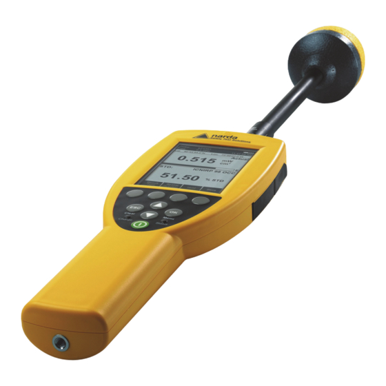
Page 26: Instrument Overview
3 Preparing the NBM-550 for use Instrument overview NBM-550 Figure 1 Device overview NBM-550 NBM-550 Narda... - Page 27 = firmware update or exceeded alarm threshold Tripod bush Electrical and optical connectors Multi-function socket for USB / GPS (optional) / external trigger Earphone Optical connector AC Adapter / Charger Tripod bush (on back of instrument) Battery compartment (on back of instrument) Narda NBM-550...
-
Page 28: Probes
3 Preparing the NBM-550 for use Probes Figure 2 Overview of probes NBM-550 Narda... - Page 29 – Green, rapid flashing: setting up communications – Green, slow flashing: data transfer in progress (flashing rate depends on measurement speed) • Charger unit connected (no data transfer possible): – Orange, rapid flashing: battery charging – Green, rapid flashing: battery fully charged Charger unit Narda NBM-550...
-
Page 30: Power Supply Nbm-550
Note: We do not recommend that you operate the instrument with the AC Adapter / Charger connected, as this can significantly degrade the measurement performance of the NBM-550. The measurement accuracy figures given in the specifications cannot then be guaranteed. Operation from rechargeable batteries The rechargeable NiMH batteries for this device are packaged separately. - Page 31 3.3 Power supply NBM-550 Charging the batteries If the device is probably not going to be used for several weeks, it should be recharged before being stored to avoid the possibility of deep discharge of the batteries. If storage is likely to be for a period of more than two months, remove the batteries from the device after recharging them.
-
Page 32: Charge State And Power Source Indicator
3 Preparing the NBM-550 for use Proper handling of rechargeable batteries Observe the following precautions when handling rechargeable batteries: • Always handle the batteries with care. • Do not drop or damage the batteries or expose them to excessively high temperatures. -
Page 33: Power Supply Ehp-50
Note: You can charge the battery with the EHP-50 switched on or off. If you connect the charger unit when a measurement is in progress, the measurement will stop and the charging cycle starts. The EHP-50 remains switched off when you unplug the charger unit. Narda NBM-550... -
Page 34: Displaying The Charge State And Power Source
The charge state of the battery is shown upper left in the display during the measurement. The same symbols are used as in the charge state display for the NBM-550 (see “Charge state and power source indicator” on page 22). -
Page 35: Probe With "Push-Pull" Connector
3.5 Connecting the probe the data sheets of the NBM-550 and probes. These documents can also be downloaded from the Narda web site on the Internet at http://www.narda-sts.com. „ NOTICE Wrong handling of the probe Damage of the probe head ... -
Page 36: Connecting And Setting Up The Ehp-50
To connect the probe: 1. Plug the black plug of the optical cable into the optical connector of the NBM-550 (Figure 1: 6c). The plug will only fit in one direction and will lock in place when light pressure is applied. -
Page 37: Fitting The Gps Module
3. Do up the knurled screw and plug the GPS module cable into the multi-function socket. 4. Reconnect the probe. Note: The GPS module can only be used with NBM-550 devices for which a GPS option was ordered and activated (see “Activating instrument options” on page 94). When... - Page 38 3 Preparing the NBM-550 for use NBM-550 Narda...
-
Page 39: Getting Started
Getting started This chapter describes how to switch on the NBM-550, the operating concept, and the initial settings. Switching on (page 30) The NBM-550 operating concept (page 32) Making basic settings (page 35) Narda NBM-550... -
Page 40: Switching On
Switch the instrument off and contact your nearest Service Center. Calibration The NBM-550 and probes must be calibrated at certain intervals to guarantee the quality of the measurement results. If you have missed the date for a calibration, this will be displayed by default after the self test is complete. -
Page 41: Gps Reception
EHP-50 measurement mode when the switch on routine has completed. If you connect or switch on the EHP-50 after you have started the NBM-550, you will have to select EHP-50 mode manually (see “Selecting EHP-50 mode manually” on page 64). -
Page 42: The Nbm-550 Operating Concept
GPS reception may be impaired by high field levels and, in particular, by field levels in the L-band (1 to 2 GHz). The NBM-550 operating concept When the self test is complete, the display switches to measurement mode. -
Page 43: The Menu Levels
4.2 The NBM-550 operating concept The menu levels The NBM-550 operating concept is context sensitive. It only displays the functions that are possible based on the probe being used, the settings selected, and the menu that is open. Settings are divided into different levels to separate... -
Page 44: Navigating In The Menus
ESC key Exits from the menu (with or without making changes) OK key Opens a menu or a function and confirms a setting ▲/▼ key Select a menu or a function and change values NBM-550 Narda... -
Page 45: Making Basic Settings
No measurement is possible during a zeroing, which takes 7s. For this period, the last measurement value is displayed and a remaining time counter is shown. If the Auto-Zero Interval function is activated, an automatic zero adjustment will be performed at the specified intervals. Narda NBM-550... -
Page 46: Setting The Auto Off Function
“Recording conditional measurements (optional)” on page 82). Changing the setting 1. Open the Auto Power-Off function (MAIN/ MEASUREMENT SETTINGS/Next/...). 2. Use the arrow keys ▲/▼ to select the desired setting and then press the OK key to confirm the setting. NBM-550 Narda... -
Page 47: Setting The Backlight
(see “Measuring with a test standard” on page 58). This is why the display unit can be selected for shaped probes as well. Narda NBM-550... -
Page 48: Changing The Units Format
Variable Triads setting. Setting the date and time Before you start using the instrument, set the date and time. This is particularly important if you want to save measured values, because the date and time of measurement are also saved. NBM-550 Narda... -
Page 49: Changing The Gps Display
Example: Lat: 48° 48’ 10.5’’ N / Lon: 9° 15’ 00.0’’ E MinDec: (-)(d)dd° mm.mmm’ • Example: Lat: 48° 48.175’ / Lon: 9° 15.000’ DegDec: (-)(d)dd.ddddd° • Example: Lat: 48.29166° / Lon: 9.25000° The default setting is DegDec. Narda NBM-550... -
Page 50: Selecting The Field Type And Units For Combination Probes
– V/m for E-fields and A/m for H-fields 3. Press the OK key to confirm the selection. Note: For simultaneous display of E and H-Field, always select the NORMAL display mode. In the other modes, display is limited to the S-Field. NBM-550 Narda... -
Page 51: Locking The Keypad
To prevent inadvertent operation of any of the keys, you can lock the keypad. Locking the keypad Press the two arrow keys ▲/▼ simultaneously. The message KEY LOCK is displayed. Unlocking the keypad Press the two arrow keys ▲/▼ simultaneously again. Narda NBM-550... - Page 52 4 Getting started NBM-550 Narda...
- Page 53 Measuring with the NBM-550 and HF probes This chapter describes how to use the NBM-550 in combination with HF probes for measurements. You can find information on how to use the EHP-50 LF Analyzer in the chapter “Measurements with the NBM-550 and EHP-50”...
-
Page 54: Measuring With The Nbm-550 And Hf Probes
5 Measuring with the NBM-550 and HF probes Avoiding measurement errors The measurement result can be falsified by external influences when measuring electromagnetic fields. Considerable measurement deviations can occur under certain circumstances, particularly when measuring low field strengths. The following tips may be of assistance in recognizing sources of interference so as to avoid measurement errors. -
Page 55: Strong Low Frequency Fields
Increase the distance from the source of low frequency interference or use a probe that has a higher frequency cutoff point at the lower end of its range. Further useful information can be found under FAQ at www.narda-sts.com Narda NBM-550... -
Page 56: Measuring In Normal Display Mode
Measuring in Normal display mode The latest measurement results are displayed in Normal mode. You can also display maximum and average values. Selecting the result type You can select the following result displays on the NBM-550: Result type Description Actual The latest measured value of field strength is shown numerically and as a bar graph. -
Page 57: Freezing A Measured Value
Press the Release key to resume the measurement. Storing a measured value You can store the measured values in an internal memory in the NBM-550 for documentation. Storing a measured value Press the Store key. The measured value displayed at the moment is stored with the date and time under the index number displayed. -
Page 58: Add Voice Comments (Optional)
5 Measuring with the NBM-550 and HF probes Add voice comments (optional) You can add a spoken comment up to 30 s in length to the stored measured values. To do this, you must activate voice recording (default setting: deactivated). -
Page 59: Setting The Averaging Time
You can measure the field strength affecting a particular space using this method. Selecting the measurement method 1. Open the Spatial AVG Mode function (MAIN/MEASUREMENT SETTINGS/Next/...). 2. Use the arrow keys ▲/▼ to select the method and press the OK key. Narda NBM-550... -
Page 60: Measuring Discrete Values
5 Measuring with the NBM-550 and HF probes Measuring discrete values ✓ You selected Discrete as the Spatial AVG Mode. 1. Press the Spatial Average key. Spatial measurement mode is displayed The result counter top left shows #0, indicating that no values have been measured yet. -
Page 61: Measuring Values Continuously
The measurement starts. The elapsed measurement time is shown top left in the display. 3. Move the NBM-550 evenly around the space to be measured. Press the Stop key to end the measurement. Pos.1 displays the measured average value. -
Page 62: Measuring In History Display Mode
5 Measuring with the NBM-550 and HF probes Measuring in History display mode You can display the progress of the measurement versus time in History mode. You can use the cursor to mark individual points on the curve and display the associated values. -
Page 63: Evaluating The Curve
The maximum and minimum values measured within the corresponding time window (interval) are displayed for these time points (see figure, left). A maximum of 200 measurement intervals are shown in the progress memory. Narda NBM-550... -
Page 64: Storing The Graphical Record
5 Measuring with the NBM-550 and HF probes Storing the graphical record The measurement values of the progress memory can be saved. To save the measurement value recording: 1. Press the Hold key to freeze the curve. 2. Press the Store History function key. -
Page 65: Display Overview
Note: You can only change the result type for the upper display area. Press the Result Type function key to select a different result type (refer to “Selecting the result type” on page 46 for information about result types). Narda NBM-550... -
Page 66: Measuring In Monitor Display Mode
5 Measuring with the NBM-550 and HF probes Measuring in Monitor display mode Monitor display mode simultaneously shows the maximum, average, and minimum measured values as well as the latest measured value. Changing to Monitor display mode ✓ The display is in measurement mode. -
Page 67: Activating The Alarm Function
2. Use the arrow keys ▲/▼ to select On and press the OK key to confirm the setting. The symbol is shown in the display when the alarm function is activated (see “Measurement screen overview” on page 32). Narda NBM-550... -
Page 68: Audible Indicator (Hot Spot Search)
5 Measuring with the NBM-550 and HF probes Audible Indicator (hot spot search) You can use the Audible Indicator function to indicate changes in field strength and determine hot spots (areas of maximum field strength). The audible signal changes according to the way the field changes: Continuous tone: Field strength is increasing •... - Page 69 2. Select the digit using the / function keys. 3. Change the value using the arrow keys ▲/▼. 4. Press the OK key when you have completed the settings to confirm them and then press the ESC key to exit from the menus. Narda NBM-550...
-
Page 70: Possible Displays When Using A Test Standard
5 Measuring with the NBM-550 and HF probes Step 3: Applying the test standard 1. Open the Apply Standard function (MAIN/MEASUREMENT SETTINGS/...). 2. Use the arrow keys ▲/▼ to select On and press the OK key. The test standard is activated, the selected frequency (Freq) is shown top left in the display. - Page 71 Probe type: E-field shaped probe Probe type: Combination (E-field and H-field) flat probe Combi probe uses: V/m, A/m Note: The S-field is shown in the upper area of the display as the product of the magnitudes of the E-field and H-field. Narda NBM-550...
-
Page 72: Measuring With A Correction Frequency
5 Measuring with the NBM-550 and HF probes 5.10 Measuring with a correction frequency All probes are calibrated in our factory to guarantee the traceability of measurements back national standards. This calibration is performed at various frequencies over the entire measurement range of the probe concerned. An... -
Page 73: Measurements With The Nbm-550 And Ehp-50
Measurements with the NBM-550 and EHP-50 This chapter describes the special functions of the NBM-550 when used with the EHP-50 LF Analyzer. You can find information about measuring with HF probes in the chapter “Measuring with the NBM-550 and HF probes”... -
Page 74: General Information
HF probe connected to the NBM-550 (HF probes have priority). If you connect the EHP-50 to an NBM-550 that has already been started and then switch it on, you will have to select the EHP-50 operating mode manually. -
Page 75: Display Types
6.2 Display types Display types The measurement settings you used last time will be applied after the EHP-50 and NBM-550 have started up. You can change the settings by opening a previously saved setup (see “Saving and loading instrument settings” on page 90) or change the measurement parameters manually. -
Page 76: General Settings
6 Measurements with the NBM-550 and EHP-50 To select the display mode: ✓ The display is in measuring mode. 1. Press the OK key to open the main menu. 2. Press the View key until the desired display mode is shown. -
Page 77: Changing The Result Type
1) All result types are shown simultaneously. 2) Only one result type can be selected at a time. Maximum The maximum measured value is retained. You can reset the maximum value and restart the measurement by pressing the ESC key. Narda NBM-550... -
Page 78: Changing The Frequency Range (Span)
6 Measurements with the NBM-550 and EHP-50 Average The average value is determined. You can set the number of measurements to be used to form the average to 4, 8, 16 or To change the number of averages: 1. Open the No. of averages function (MAIN MENU/MEASUREMENT SETTINGS/...). -
Page 79: Wpm Display Mode (Weighted Peak Method)
The EHP-50F supports exposure level evaluation according • ICNIRP 1998, public • ICNIRP 1998, occupational • ICNIRP 2010, public • ICNIRP 2010, occupational • Directive 2013/35/EU, Limbs Action Levels • Directive 2013/35/EU, High Action Levels • Directive 2013/35/EU, Low Action Levels Narda NBM-550... - Page 80 6 Measurements with the NBM-550 and EHP-50 WPM display mode displays the percentage of the limit value that has been reached referred to the selected safety standard (wideband value from 1 Hz to 400 kHz) and a graph of the field strength value versus time.
-
Page 81: Spectrum Display Mode
Graphical display of field strength with indication of selected field type (E-field in the example) Spectrum with information about: – 1 kV/m: field type and measurement range – 100 Hz: span (in addition to display top left). The logarithmic axis scale always spans 6 decades. Narda NBM-550... - Page 82 6 Measurements with the NBM-550 and EHP-50 To use the marker function: You can use the marker to read out each separate evaluation frequency in the spectrum of the FFT analysis. 1. Press the Marker function key (the key is labeled OFF when the marker function is active).
-
Page 83: Standard Display Mode
3. Press the Highest value function key to move the marker to the highest value on the trace. Other functions The other functions are the same for all display modes and are described under “General settings” on page 66. Narda NBM-550... -
Page 84: Xyz Display Mode
6 Measurements with the NBM-550 and EHP-50 XYZ display mode XYZ display mode allows you to display the numerical measurement results for each separate axis of the EHP-50 as well as the isotropic value (RSS). This display mode is useful for optimum alignment of the EHP-50 and allows you to see if an axis is overdriven and correct this by adjusting the alignment. -
Page 85: Other Settings
80 for more information. The selected time interval is temporarily increased automatically in LF mode if the measuring time of the EHP-50 makes a longer interval time necessary. The interval time menu parameter is not changed though. This Narda NBM-550... - Page 86 6 Measurements with the NBM-550 and EHP-50 means that 1 s will be displayed even if an interval time of 10 s is necessary, for example. The table below shows the relationship between span and timer interval: Span Timer interval ≥...
-
Page 87: Managing Result Data
You can save and recall your device settings in a setup in the same way as in HF mode. All EHP-50-specific settings are saved separately. This also applies to the selected standard. See “Saving and loading instrument settings” on page 90 for more information. Narda NBM-550... - Page 88 6 Measurements with the NBM-550 and EHP-50 NBM-550 Narda...
-
Page 89: Recording And Managing Measured Values
(Data Logger) and how to recall and manage the measurement data that you have recorded manually or automatically. Storage types (page 80) Recording measurements by timer control (page 80) Recording conditional measurements (optional) (page 82) Managing result data (page 84) Narda NBM-550... -
Page 90: Storage Types
1. Set the recording parameters: – enter the starting time (Timer Start), – enter the recording time (Timer Duration), – enter the recording interval (Timer Interval). 2. Select Timer Logging function to start the recording. These steps are explained below. NBM-550 Narda... -
Page 91: Setting The Recording Parameters
The maximum duration is determined by the selected interval time (see table below), because the number of measurement intervals is limited to 32000. Interval Maximum duration time (HH:MM:SS) (seconds) 8:53:20 17:46:40 26:40:00 44:26:40 88:53:20 > 10 99:59:59 Narda NBM-550... -
Page 92: Starting The Recording
– enter the starting condition (Store Condition), – enter the store range (Store Range), – enter the upper threshold, – enter the lower threshold. 2. Start the recording: – select the Condition Logging function, – press Start. These steps are explained below. NBM-550 Narda... -
Page 93: Setting The Recording Parameters
5. To enter the lower threshold (only effective at OUT of Gap): – open the Lower Threshold function, – select the threshold value with the arrow keys ▲/▼ (only effective at OUT of Gap) and press the OK button to apply the settings. Narda NBM-550... -
Page 94: Starting / Stopping The Recording
Data Viewer Overview of all stored data sets and Last data set only display of the measurement results Note: Before final deletion of data sets, a warning notice always appears giving you the option to cancel the deletion process. NBM-550 Narda... -
Page 95: Using The Memory Manager
Type Storage type: • CON: Condition Logging • HST: History mode • MON: Monitor mode • NOR: Normal mode • SPA: Spatial Averaging • TIM: Timer controlled (Timer Logging) • XYZ: XYZ mode A comment has been added. Narda NBM-550... -
Page 96: Data Viewer Display Examples
Display Meaning Values Timer display mode Data Viewer Display is in Data Viewer mode Timer Values were stored by timer control Index 0004 The series of values was stored at memory position 4. First value in the series NBM-550 Narda... - Page 97 ✓ The earphone must be connected for playback. Press the Play function key. This function is available from the overview list view and the selected measurement view. The comment is played back. Narda NBM-550...
- Page 98 7 Recording and managing measured values Deleting a data set Note: You can only ever delete the last entry in the memory. ✓ The overview list is open. Press the Delete Latest function key. The last (latest) entry is deleted. NBM-550 Narda...
-
Page 99: Setup And Configure
Setup and configure This chapter describes additional functions and settings for the interface, for instrument information and settings, as well as for use of the NBM-550 as a controller and for the activation of new instrument options. Configuring the interface (page 90) -
Page 100: Configuring The Interface
Power On = Default. Setup 1-8 Memory positions User Indicates that a user setup is stored at this memory position Factory Indicates that the factory default settings apply because a user setup has not been stored NBM-550 Narda... -
Page 101: Changing A Setup Name
You can change the names of setups using the NBM-TS PC software supplied with the device. To change setup names: 1. Upload the setups to your PC using the NBM-TS PC software. 2. Edit the names on your PC and then transfer the setups back to the instrument. Narda NBM-550... -
Page 102: Setting The Power On Behavior
Setting the power on behavior You can use the Power On function to specify the instrument setup that is loaded when you switch on the NBM-550. The following settings are possible: Previous: The settings in use when the instrument was •... -
Page 103: Using The Nbm-550 As A Controller
8.4 Using the NBM-550 as a controller Using the NBM-550 as a controller You can use the NBM-550 to control other instruments from Narda Safety Test Solutions such as the NBM-520 or another ▲/▼. This allows you to measure in places that are difficult to reach with convenient operation and reading of results. -
Page 104: Activating Instrument Options
You can find other tips in the PC software's online help. Note: The activation code of an option is linked to the serial number of the instrument. For this reason, be sure to specify the serial number of the NBM-550 being used when placing subsequent orders. NBM-550... -
Page 105: Pc Software
This chapter gives you some basic information about the NBM-TS PC software. It explains the possible applications of the software, how to connect the NBM-550 to the PC and the settings you need to make on the NBM-550. It also describes how to update the firmware of the NBM-550 via the PC software. -
Page 106: Using The Pc Software
9 PC software Using the PC software The NBM-TS PC software is included with the NBM-550. The PC software provides a large number of functions: • Visualization of stored measurement results • Off-line analysis of stored results • Remote control of the NBM-550, including live signals on the PC (not available for LF mode with the EHP-50) •... -
Page 107: Connecting The Nbm-550
Connecting the NBM-550 to a PC 1. Configure the interface (see “Configuring the interface” on page 90). Connect the NBM-550 to the PC using a USB cable or an optical cable. The NBM-550 will be detected as a new device auto- matically by the PC. -
Page 108: Updating The Firmware
9 PC software Updating the firmware You can update the firmware of the NBM-550 in order to make use of new or improved functions. You can only update the firmware using a PC on which the NBM-TS PC software has been installed. -
Page 109: Performing A Reset
Note: A reset does not change any instrument parameters, it only restarts the instrument. Clear Menu Use the Setup menu to reset the instrument to the factory default settings (see “Saving and loading Charge Status instrument settings” on page 90). Narda NBM-550... - Page 110 9 PC software NBM-550 Narda...
-
Page 111: Overview Of All Menus And Functions
Overview of all menus and functions This chapter describes all the menus and functions of the NBM-550. 10.1 Measurement menus (page 102) 10.2 Main menu (page 103) 10.3 Measurement Settings (HF mode) (page 104) 10.4 Measurement Settings (LF mode) (page 106) 10.5... -
Page 112: Measurement Menus
Hold Freezes the current (actual) measured value. The function key label changes to Release after you press Hold, and Hold flashes in the display. Press it to unfreeze the measurement value. Store Stores the current (actual) measurement value NBM-550 Narda... -
Page 113: Main Menu
• Display a list of all saved measured values. • Display saved measured values. • Delete the last measured value saved. 1) See Chapter 6 for LF measurements with EHP-50 2) Only displayed when EHP-50 display is OFF Narda NBM-550... -
Page 114: Measurement Settings (Hf Mode)
Next Open page 2 of the menu Note: The language selection is deliberately at the top of the menu. This makes it easy for you to revert to the original setting if you change the language by mistake. NBM-550 Narda... -
Page 115: 105
Cal. Date Check the calibration date when the instrument Check is switched on: On, Off Function keys Unit:... Select the measured value units: , mW/cm , V/m, A/m Back Open page 1 of the menu Narda NBM-550... -
Page 116: Measurement Settings (Lf Mode)
EHP-50F. You cannot retrospectively download standards via the NBM. Default: 2013/35/EU Low ALs Alarm Function Activate alarm function: On, Off Alarm Limit Set the alarm limit Function keys Next Open page 2 of the menu NBM-550 Narda... -
Page 117: 107
• Permanent: Always on • Off: Always off • 5 s, 10 s, 30 s, 60 s Cal. Date Check the calibration date when the instrument Check is switched on: On, Off Function keys Back Open page 1 of the menu Narda NBM-550... -
Page 118: Data Logger
• First and Last: Only the first and last values occurring during the period when the Store Condition was fulfilled are recorded. • Store all: All measured values that fulfill the 3) 4) Store Condition are recorded. Upper Upper threshold for Condition Logging Threshold (optional) NBM-550 Narda... - Page 119 Data Viewer (see “Using the Data Viewer” on page 85). It should be noted that only the first 999 sub data sets (intervals or events) can be displayed on the NBM-550. The NBM-TS PC software enables complete evaluation of all data.
-
Page 120: Memory Manager
Free Memory Free memory space. Function keys Delete Latest Delete the last saved set of measured values (i.e. the displayed set). Delete All Delete all saved sets of measured values. Play Replay the voice recording (if one exists). NBM-550 Narda... -
Page 121: Interface
PC: • USB: Connection via USB cable to the multi- function socket • Optical: Connection via optical duplex cable, type RP-02 Controller Use the NBM-550 to control another NBM-5xx Function instrument: On, Off External Trigger storage externally: On, Off Trigger... -
Page 122: Information
• Upper Frequency Limit: Greatest frequency that can be measured Device Service information Diagnostic • Temperature • Battery voltage • Battery capacity Checking instrument functions (see “Checking Probe Test instrument functions” on page 120) NBM-550 Narda... -
Page 123: Setup
Delete Deletes the user setup stored in a memory position. Load Loads the user setup stored in a memory position. Save Saves the current setup to a memory position. Narda NBM-550... -
Page 124: 10.10 Clock
You can set the time and date in the CLOCK menu. Function Meaning Time Sets the time. Time Format Sets the time format: • 12 h clock • 24 h clock Date Sets the date. Date Format Sets the date format: • mm/dd/yyyy • dd.mm.yyyy • yyyy-mm-dd NBM-550 Narda... -
Page 125: Instrument Maintenance
This chapter describes how to clean the instrument and how to replace the batteries. 11.1 Cleaning the instrument (page 116) 11.2 Replacing / removing the batteries (page 117) 11.3 Disposal (page 119) 11.4 Checking instrument functions (page 120) Narda NBM-550... -
Page 126: Cleaning The Instrument
1. Use a soft cloth to clean the instrument. You can use lukewarm water to which a little detergent solution has been added as a cleansing agent. 2. To prevent streaks and spots, wipe off the instrument with a dry cloth while it is still damp. NBM-550 Narda... -
Page 127: Replacing / Removing The Batteries
Never touch both poles of the batteries simultaneously with a metal object. Always close the battery compartment immediately after replacing batteries. Never use the NBM-550 with the battery compartment open. WARNING Reverse charging of rechargeable batteries NiMH batteries can explode if you charge them with reversed poles ... - Page 128 Make sure you insert them the right way round according to the diagram on the base of the battery compartment. 5. Close the battery compartment. 6. Connect the AC Adapter / Charger and charge the batteries (a complete charge cycle takes about 2 hours). NBM-550 Narda...
-
Page 129: Disposal
Within the European Union, all electronic measuring systems purchased from Narda after 13th August 2005 can be returned when they reach the end of their useful life. The measuring systems that come under this regulation or the documents that accompany them are clearly marked with the symbol of a garbage bin crossed out with black lines. -
Page 130: Checking Instrument Functions
This is especially important for thermocouples because the sensors can be affected by various mechanical and environmental stressors. Narda offers portable sources to accomplish this important step (see “Accessories” on page 135). Before beginning any RF radiation measurement, always advise yourself of the frequencies and field strengths that you could expect to encounter. - Page 131 All 3 channels must respond to the field source. It is no fault if some channels display identical values. The meaning of the channels varies depending on the type of probe and is irrelevant for this test. For more details about the probe, refer to the data sheet. Narda NBM-550...
-
Page 132: Appropriate Test Sources
EB5091 – – EC5091 – – ED5091 – – EF5091 – EF5092 – 1) PMR Pocket Radios are commonly available in electronics stores. 2) Model 8699 only available for North America. NBM-550 Narda... -
Page 133: Specifications
Specifications This chapter lists the specifications of the NBM-550. For the EHP-50 a separate data sheet is provided. 12.1 Display (page 124) 12.2 Measurement functions (with HF probes) (page 124) 12.3 Result memory (page 125) 12.4 Interfaces (page 125) 12.5 Options (page 126) 12.6... -
Page 134: Display
Starting time setting: Up to 24 h in advance or record immediately Recording time: up to 100 h (Timer Logging) Store interval: Every 1 s to 6 min (in 11 steps) Number of store intervals: up to 32000 NBM-550 Narda... -
Page 135: Result Memory
Via multi-function plug connector. The GPS receiver with connection cable is contained in the GPS option. Probe connection Plug-and-play with automatic detection, compatible with all NBM-series probes, integration time for measuring input approx. 270 ms, measurement sampling rate 5 Hz (5/50/60 Hz for remote operation) Narda NBM-550... -
Page 136: Options
– First and last result (for which the condition is fulfilled) Voice comments (Voice Recorder) Microphone Built-in microphone on top of instrument close to the Narda logo Record level Fixed level, VU meter display for checking the level during recording... -
Page 137: General Specifications
Weight transport case 4.2 kg (empty) Accessories (included) Hard shell case, AC Adapter / Charger, batteries, shoulder strap, table top tripod, NBM-TS software, operating manual, calibration certificate, USB interface cable 1) only for basic instrument; probes are specified separately Narda NBM-550... -
Page 138: Standards Compliance
-40 °C to +70 °C • Operation 0 °C to +40 °C 12.9 EHP-50 The specifications for the EHP-50 are contained in the EHP-50 operating manual, which is provided as a PDF file on the CD of the EHP-TS PC software. NBM-550 Narda... -
Page 139: 12.10 Ce Declaration Of Conformity
12.10 CE Declaration of Conformity 12.10 CE Declaration of Conformity Narda NBM-550... - Page 140 12 Specifications NBM-550 Narda...
-
Page 141: 12.11 Declarations Of Origin
12.11 Declarations of origin 12.11 Declarations of origin NBM-550 Germany EHP-50 Italy Narda NBM-550... - Page 142 12 Specifications NBM-550 Narda...
-
Page 143: Ordering Information
Ordering information This chapter contains the information needed for ordering the NBM-550, together with its probes and accessories. 13.1 NBM-550 (page 134) 13.2 Probes (page 134) 13.3 Accessories (page 135) Narda NBM-550... -
Page 144: Nbm-550
• Software, NBM-TS, PC Transfer (2400/93.01) • Operating Manual NBM-550 • Calibration Certificate Probes are not included Options Set for NBM-550: GPS, Voice Recorder, Conditional Logging includes: 2401/40 • GPS Receiver for NBM-550 • GPS Mounting Set • Earphone, 3.5 mm Plug •... -
Page 145: Low Frequency Probes
13.3 Accessories Low frequency probes EHP-50F E&H Field Analyzer Set, 1 Hz – 400 kHz, for NBM-550 2404/103 Set includes: • EHP-50F Basic Unit (2404/03) • AC/DC Battery Charger, for EHP-50 (2259/92.08) • FO Duplex RP-02 Cable, 10 m (2260/91.07) •... - Page 146 13 Ordering information NBM-550 Narda...
-
Page 147: Glossary
Glossary This chapter explains some important terms that are used in this operating manual. Narda NBM-550... - Page 148 Global Positioning System The Global Positioning System is a satellite supported navigation system belonging to the US Defense Ministry that is used for determining the position of any location in the world. NBM-550 Narda...
- Page 149 (Coarse/Acquisition Code) and is available for general, civilian use. S-field Product of E-field and H-field, expressed as power density or electromagnetic power flux density. The power density S is expressed in Watts per unit area: S = [W/m (or [mW/cm ] or [μW/cm Narda NBM-550...
- Page 150 WGS84 is a system used for surveying the earth, which was introduced by the Americans in 1984 along with the triumph of satellite navigation. WGS84 includes both the reference point as well as the ellipsoid and is the geodetic basis for GPS. NBM-550 Narda...
-
Page 151: Index
Connecting and setting up, EHP-50 26 Selecting the operating mode 64 Connecting the probe 24 Spectrum 71 Continuous spatial measurement 51 Standard 73 Contrast 37 Switching on 31 Controller operation 93 Weighted Peak method (WPM) 69 Correction frequency, measuring with 62 XYZ 74 Narda NBM-550... - Page 152 Isotropy 139 Items included 12 Packaging 12 PC software, using the 96 Power supply Locking the keypad 41 EHP-50 23 NBM-550 20 Probe test 120 Main menu 103 Proper use 8 Managing result data 84 Measured values Freezing 47 Rechargeable batteries...
- Page 153 Test sources, appropriate 122 Test standard, measuring with a 58 Time and date setting 38 Transport and storage 15 Transport case 14 Transport damage 13 Trigger cable 47 Tripod, using the 27 Unpacking 12 Updating the firmware 98 USB 140 Narda NBM-550...
- Page 154 Index NBM-550 Narda...
- Page 156 Narda Safety Test Solutions GmbH Sandwiesenstraße 7 72793 Pfullingen, Germany Phone: +49 7121-9732-0 Fax: +49 7121-9732-790 E-mail: support.narda-de@L-3com.com www.narda-sts.com Narda Safety Test Solutions 435 Moreland Road Hauppauge, NY 11788, USA Phone: +1 631-231-1700 Fax: +1 631-231-1711 E-mail: nardasts@L-3com.com www.narda-sts.us Narda Safety Test Solutions Srl...
Need help?
Do you have a question about the NBM-550 and is the answer not in the manual?
Questions and answers