Advertisement
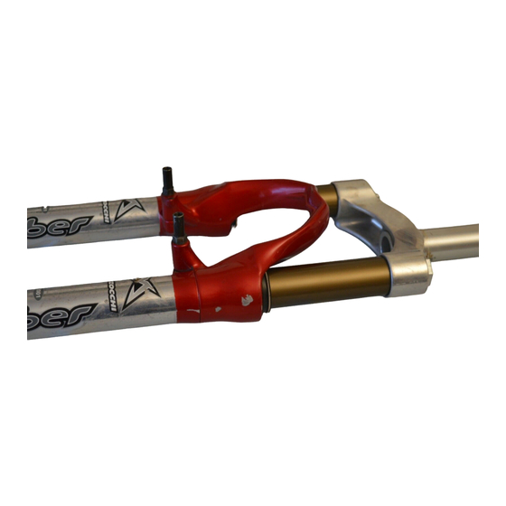
X-FLY
(80)
175
+0.05
Ø30
0
80
+0.1
100
0
130
G E N E R A L
18
• Special air/oil damped cross-country fork: each leg uses pressu-
rized air blown through a special valve on stanchion caps as
damping medium.
• The right leg rebound is damped by a hydraulic cartridge.
• Rebound damping adjustment controlled via external top right leg
adjuster.
• Stanchions fitted into lower Crown by cryofit technique. Full length
bushings guarantee superior rigidity.
• Sliders and arch are an integral assembly for reduced weight and
improved rigidity.
• Parts subjected to friction are cooled and lubricated by a specially
Ø30
formulated oil.
Steer tube: EASTON aluminum steer tube available for 1 1/8"
diameter, threadless.
Crown: Forged and CNC-machined BAM aluminum alloy.
Arch: Cast magnesium alloy.
Stanchions: anodized aluminum with variable section.
0
15
-0.1
Sliders: Forged and CNC-machined BAM aluminum alloy. Left
+1
20
0
slider comes with supports for disc brake caliper.
Slider bushing: Full length guide bushings composed of a copper
base and impregnated with an anti-friction coating.
Seals: Computer designed oil seals guarantee the highest quality
seals available.
Oil: Specially formulated oil which eliminates foaming and viscosity
breakdown while providing complete stiction-free performance.
Fork leg oil: type EBH 16 - SAE 7.5.
– right leg 110 cc,
– left leg 85 cc.
+0.1
9.2
0
25
BAM: Bomber Aerospace Material.
Special alloy developed from aerospace material.
Advertisement
Table of Contents

Related Manuals for Marzocchi X-Fly 80


Summary of Contents for Marzocchi X-Fly 80
- Page 1 G E N E R A L • Special air/oil damped cross-country fork: each leg uses pressu- rized air blown through a special valve on stanchion caps as damping medium. • The right leg rebound is damped by a hydraulic cartridge. +0.05 Ø30 •...
- Page 2 G E N E R A L • Special air/oil damped cross-country fork: each leg uses pressu- rized air blown through a special valve on stanchion caps as damping medium. +0.05 Ø30 • The right leg rebound is damped by a hydraulic cartridge. •...
-
Page 3: General Rules
I N S T R U C T I O N S GENERAL RULES 1. Where specified, assemble and disas- semble the shock absorption system using the M special tools only. ARZOCCHI 2. On reassembling the suspension sys- tem, always use new seals. 3. -
Page 4: Failures, Causes And Remedies
FAILURES, CAUSES AND REMEDIES This paragraph reports some failures that may occur when using the fork. It also indicates possible causes and suggests a remedy. Always refer to this table before doing any repair work. FAILURES CAUSES REMEDIES X-FLY Oil leaking through the top of the slider 1. -
Page 5: Disc Brake System Assembly
RECOMMENDATIONS I N S T A L L A T I O N M A I N T E N A N C E Installing the fork on a bicycle is a very DISC BRAKE SYSTEM ASSEMBLY delicate operation that should be carried forks are based on advanced WARNING: If a disc brake sys- ARZOCCHI... -
Page 6: Rebound Adjustment
A D J U S T M E N T S REBOUND ADJUSTMENT FORK LEG PRESSURIZATION The right fork leg is equipped with an Blow pressurized air through the valves to adjuster screw (A) for REBOUND damp- set COMPRESSION damping. To change ing. -
Page 7: Disassembly Diagram
D I S A S S E M B L Y GENERAL – The reference numbers given in this section relate to the components shown in the fork exploded view. – Before starting any operation. please read the diagram below. It shows the quickest procedure and the exact disassembling sequence. - Page 8 FIG. 1 FIG. 2 (only right leg) FIG. 3 Depressurize each fork leg (see section Lock the check nut (26) and remove the Push the stanchions (1) into the sliders ADJUSTMENT). cap (7) from hydraulic cartridge end (18) and let all the oil drain out from the Unscrew the caps (6) and (7) with a 21 (12).
- Page 9 HYDRAULIC CARTRIDGE CHANGE FIG. 5 (only right leg) FIG. 6 (only left leg) AND PUMPING ROD CHANGE Pull the hydraulic cartridge (12) complete A pumping rod (8) complete with re- FIG. 4 with rebound spring (9) and foot washer bound spring (9) and foot washer (23, Turn the fork leg upside-down and un- (23, see exploded view) out of the R.H.
- Page 10 FIG. 7 FIG. 8 FIG. 9 Withdraw the crown and stanchions as- Remove the dust seal (13) from the top of Remove the stop ring (14) from the sliders sembly (1) from the sliders (18). the sliders using a small screwdriver. by placing the screwdriver bit in one of the three openings on the stop ring.
- Page 11 FIG. 10 FIG. 11 FIG. 12 Fit the slider protector (A) onto the slider Remove the upper washer (16) from the Fit the bit of a small screwdriver into upper and remove the oil seal (15) with the help slider. edge slot of the pilot bushing (17) and lift of a large screwdriver.
- Page 12 REPLACING AIR VALVE FIG. 13 This operation can be performed when fork is fully assembled and fitted on bike, but only after draining inner pressure. If the air valve is disassembled with the fork removed, keep the fork vertical so as to avoid any oil leakage.
- Page 13 R E A S S E M B L Y CAUTION: before reassembling, all metal FIG. 15 FIG. 16 components should be washed carefully Fit the upper washer (16) into the slider so Lubricate the oil seal (15) and place it with inflammable, preferably biodegrad- that it touches the pilot bushing.
- Page 14 FIG. 17 FIG. 18 CROWN AND STANCHIONS Insert the stop ring (14) into the slider Lubricate the dust seals (13) and fit them ASSEMBLY making sure it is properly seated into into the stanchions from the spring end. FIG. 19 place.
- Page 15 HYDRAULIC CARTRIDGE (right leg) FIG. 21 HOW TO FILL WITH OIL AND PUMPING ROD (left leg) Lubricate O-Rings (19) on the foot nuts FIG. 22 RE-ASSEMBLY (20) and screw them onto the pumping Pour oil little by little when the stanchions FIG.
- Page 16 FIG. 23 (only right leg) FIG. 24 Screw the cap (7) on hydraulic cartridge Lubricate O-Rings (5) on caps and lift the end (12) and tighten to proper torque. stanchions, start the cap (7) onto the Lock check nut on cap. threads by hand.
-
Page 17: Specific Marzocchi Tools
SPECIFIC MARZOCCHI TOOLS R e f . I t e m . Description and use R 5089 AB Slider protector: to remove the oil seal from the slider R 5090 Oil seal press: to press oil seal into the slider...
Need help?
Do you have a question about the X-Fly 80 and is the answer not in the manual?
Questions and answers