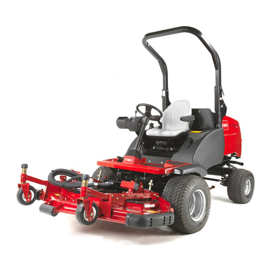
Toro Groundsmaster 3400 Operator's Manual
4-wheel drive traction unit
Hide thumbs
Also See for Groundsmaster 3400:
- Operator's manual (52 pages) ,
- Addendum (4 pages) ,
- Operator's manual (28 pages)

Related Manuals for Toro Groundsmaster 3400


Summary of Contents for Toro Groundsmaster 3400
- Page 1 Form No. 3399-521 Rev A Groundsmaster ® 3400 4-Wheel Drive Traction Unit Model No. 30651—Serial No. 314000001 and Up G018031 *3399-521* A Register at www.Toro.com. Original Instructions (EN)
- Page 2 You are responsible for operating the product properly and safely. You may contact Toro directly for product and accessory information, help finding a dealer, or to register your product. Whenever you need service, genuine Toro parts, or additional...
-
Page 3: Table Of Contents
Removing Debris from the Cooling System ....40 Safety ................4 Brake Maintenance ............41 Safe Operating Practices........... 4 Towing the Mower..........41 Toro Riding Mower Safety ........5 Belt Maintenance ............43 Sound Power Level ..........6 Tensioning the Alternator Belt .........43 Sound Pressure Level..........6 Controls System Maintenance ........43... -
Page 4: Safety
Safety • Warning—Fuel is highly flammable. Take the following precautions: – Store fuel in containers specifically designed for this This machine has been designed in accordance with EN purpose. ISO 5395:2013. – Refuel outdoors only and do not smoke while Improper use or maintenance by the operator or owner refuelling. -
Page 5: Toro Riding Mower Safety
Toro Riding Mower Safety crossing roads and sidewalks. Stop cutting unit if not mowing. The following list contains safety information specific to Toro • Do not operate the mower while sick, tired, or under the products or other safety information that you must know that influence of alcohol or drugs. -
Page 6: Sound Power Level
Keep everyone away. • Wearing safety shoes is advisable and required by some • To ensure safety and accuracy, have an Authorized Toro local ordinances and insurance regulations. Distributor check the maximum engine speed with a •... - Page 7 Measured vibration level for right hand = 1.5 m/s Uncertainty Value (K) = 0.8 m/s Measured vibration level for left hand = 1.0 m/s Uncertainty Value (K) = 0.5 m/s Measured values were determined according to the procedures outlined in EN ISO 5395. Whole Body Measured vibration level = 0.5 m/s Uncertainty Value (K) = 0.3 m/s...
-
Page 8: Safety And Instructional Decals
Safety and Instructional Decals Safety decals and instructions are easily visible to the operator and are located near any area of potential danger. Replace any decal that is damaged or lost. 950889 70-13-072 1. Warning—hot surfaces. 1. Jacking point 111-0773 950832 1. - Page 9 111–5233 111-3566 1. Slow 4. Float the cutting unit over the ground 1. Falling, crushing hazard—ensure platform latch in engaged 5. Neutral cutting unit 2. Continuous variable before operating. engine speed 3. Fast 6. Raise the cutting unit 111-3567 1. Pedal operation 111-3344 1.
-
Page 10: Setup
Setup Loose Parts Use the chart below to verify that all parts have been shipped. Procedure Description Qty. Tire pressure gauge (not supplied) Check the tire pressure. Operator's Manual Engine Operator's Manual Read the Operator's Manual before operating the machine. Parts Catalog CE certificate Note: Determine the left and right sides of the machine... -
Page 11: Product Overview
Controls Product Overview Control Panel Components 12 15 13 16 8 2 3 4 G018144 Figure 2 1. Cutting unit 4. Operator's seat 5. Hood 2. Control arm 3. Steering wheel G018032 Figure 3 1. Parking-brake switch 10. Horn button (supplied with light kit) 2. - Page 12 WARNING The parking brake operates on the front wheels only. Do not park the mower on a slope. g018033 Figure 4 1. Weight-transfer control G018029 Figure 6 1. Parking brake Service Brake Service braking is achieved by the hydraulic transmission system.
- Page 13 Throttle Control Operate the throttle control in a forward direction to increase the engine speed. Operate the throttle control in a rearward direction to reduce engine speed (Figure Note: The engine speed dictates the speed of the other functions (i.e., travel, cutting-blade rotation speed and cutting unit lift speed).
- Page 14 Operator Seat WARNING Never operate the mower without first checking that the operator seat mechanisms are in good working order and that, once adjusted and locked, the seat remains securely in position. Adjustment of the seat mechanisms should only be carried out when the mower is at a standstill with the parking brake engaged.
- Page 15 Warning Systems Hydraulic-Fluid Overheating Warning Light and Horn The hydraulic-fluid warning light illuminates when Engine-Coolant Overheating Warning Light overheating occurs. The horn is actuated when the hydraulic fluid in the reservoir exceeds 95 degrees C (203 degrees F) The engine-coolant warning light illuminates, the mower deck as shown in Figure stops, and the horn is actuated...
- Page 16 Low Battery-Charge Warning Light Low Engine-Oil Pressure Warning Light The battery-charge warning light illuminates when the low The engine-oil pressure warning light illuminates when the oil battery charge is low (Figure 13). pressure is too low (Figure 14). G018081 G018037 Figure 14 Figure 13 1.
- Page 17 Ignition Key Engine Pre-Heat Indicator Light 0 = Engine off Turn the ignition key to position II. The engine pre-heat indicator light will illuminate and heat the glow plugs (Figure I = Engine run/Auxiliary on 16). II = Engine pre-heat Important: Attempting to start a cold engine before III = Engine start using the pre-heat can cause unnecessary wear to the...
- Page 18 Hour Meter Transmission Neutral-Indicator Light The hour meter shows the total hours that the machine has This light illuminates when the travel control pedal is in the been operated (Figure 18). position and the ignition key is turned to position NEUTRAL (Figure 19).
- Page 19 Cutting Unit Drive-Switch Indicator Light This light illuminates when the cutting-unit-drive switch is in the position and the ignition key is turned to FORWARD position I (Figure 20). G029106 Figure 20 1. Indicator light for the cutting-unit-drive switch...
-
Page 20: Specifications
Engine Kubota 26.5 kw (35.5 hp) at 2000 rpm DIN 70020 Attachments/Accessories A selection of Toro approved attachments and accessories are available for use with the machine to enhance and expand its capabilities. Contact your Authorized Service Dealer or Distributor. -
Page 21: Operation
0 degrees F) • Alternate oil: SAE 10W-30 or 5W-30 (all temperatures) Toro Premium Engine oil is available from your distributor in either 15W-40 or 10W-30 viscosity. Note: The best time to check the engine oil is when the engine is cool before it has been started for the day. If it has already been run, allow the oil to drain back down to the sump for at least 10 minutes before checking. -
Page 22: Checking The Cooling System
Checking the Cooling System Use only clean, fresh diesel fuel with low (<501 ppm) or ultra low (<15 ppm) sulfur content. The minimum cetane rating Service Interval: Before each use or daily is 40. To ensure fuel freshness, purchase fuel in quantities that is used within 180 days. -
Page 23: Checking The Hydraulic Fluid
Toro Biodegradable Hydraulic Fluid (Available in 5 gallon pails or 55 gallon drums. See parts catalog or Toro • If a fuel dispenser nozzle must be used, keep the distributor for part numbers). -
Page 24: Checking The Wheel Nut Torque
Securing the Platform 1. Lower the platform carefully. The gas spring will provide assistance. 2. Move the locking handle towards the front of the mower as the platform nears the fully lowered position. Note: This will ensure that the latch hooks clear the locking bar. -
Page 25: Starting And Stopping The Engine
4. After preheating the glow plugs, turn key to the START WARNING position (III) and hold it to start the engine. Do not operate the mower if the operator-presence Note: Crank the engine for no longer than 15 seconds. controls are not functioning. 5. -
Page 26: Using Cutting-Unit Position Control
Stopping the Engine Engaging the Cutting Unit Drive 1. Move all controls to the N position, set the EUTRAL parking brake, move the throttle to the low-idle position, and allow the engine to reach low-idle speed. Important: Allow the engine to idle for 5 minutes before shutting it off after a full load operation. -
Page 27: Folding The Rops
4. Insert the retaining bolts in the lower hole and fully tighten the hand nuts to support the roll bar in its lowered position. 5. To raise the frame, follow these instructions in reverse order. WARNING If the ROPS is not properly installed or fully tightened, it will not provide full protection in the event of a roll-over. -
Page 28: Jacking Points
Jacking Points Note: Use jack stands to support the machine when required (Figure 31). • Front—under the rear lift cylinder mount. • Rear—axle tube on the rear axle. Raising The Mower off the Ground WARNING A raised mower deck that is not properly supported can fall, crushing you or bystanders who are underneath it. -
Page 29: Transporting Machines
Transporting Machines Quality of Cut The quality of cut will deteriorate if the forward speed is WARNING excessive. Always balance the quality of cut with the work rate required and set the forward speed accordingly. Driving on the street or roadway without turn signals, lights, reflective markings, or a slow Engine moving vehicle emblem is dangerous and can lead... -
Page 30: Maintenance
Maintenance Note: Determine the left and right sides of the machine from the normal operating position. Note: Download a free copy of the schematic by visiting www.Toro.com and searching for your machine from the Manuals link on the home page. -
Page 31: Daily Maintenance Checklist
Maintenance Service Maintenance Procedure Interval • Drain and clean the fuel tank. Before storage • Flush and replace the cooling system fluid. • Replace all moving hoses. Every 2 years • Replace the transmission cable. Daily Maintenance Checklist Duplicate this page for routine use. For the week of: Maintenance Check Item Mon. -
Page 32: Pre-Maintenance
Important: Regular maintenance is essential for the continued safe operation of the machine. Correct servicing will prolong the working life of the machine and safeguard the w3arranty. Always use genuine Toro service parts as these are accurately matched to the required duty. -
Page 33: Lubrication
Lubrication Lubricate bearings and bushings immediately after every washing, regardless of the interval listed. Replace any damaged grease fittings. Greasing the Bearings, Grease all grease points and ensure that sufficient grease is Bushings, and Pivots injected such that clean grease is seen to escape. This ensures maximum working life. -
Page 34: Engine Maintenance
Engine Maintenance Checking the Engine-Overheat-Warning System Service Interval: Every 500 hours G014565 Figure 34 2. Before removing the filter, use low-pressure air (40 psi, clean and dry) to help remove large accumulations of debris packed between outside of the filter and the canister. -
Page 35: Servicing The Engine Oil And Filter
8. Install the cover orienting the rubber outlet valve in a downward position—between approximately 5 o’clock to 7 o’clock when viewed from the end. 9. Check the condition of the air cleaner hoses. 10. Secure the cover. Servicing the Safety Filter The air filter has a secondary safety-filter element inside the primary air filter to prevent dislodged dust and other items from entering the engine while changing the main element. -
Page 36: Fuel System Maintenance
Fuel System Maintenance DANGER Under certain conditions, diesel fuel and fuel vapors are highly flammable and explosive. A fire or explosion from fuel can burn you and others and can cause property damage. • Use a funnel and fill the fuel tank outdoors, in an open area, when the engine is off and is cold. -
Page 37: Draining The Fuel Tank
Electrical System DANGER Under certain conditions, diesel fuel and fuel Maintenance vapors are highly flammable and explosive. A fire or explosion from fuel can burn you and others and Important: Before welding on the machine, disconnect can cause property damage. both cables from the battery and the terminal connector from the alternator to prevent damage to the electrical •... -
Page 38: Servicing The Battery
Servicing the Battery Drive System Maintenance Service Interval: Every 250 hours DANGER Changing the Battery electrolyte contains sulfuric acid, a deadly Transmission-Oil Filter poison that can cause severe burns. • Do not drink electrolyte and avoid contact with Service Interval: After the first 50 hours skin, eyes, or clothing. -
Page 39: Checking The Rear Wheel Alignment
Checking the Rear Wheel Alignment Service Interval: Every 500 hours To prevent excessive tire wear and ensure safe machine operation, align the rear wheels to 3 to 8 mm (0.12 to 0.31 inch). 1. Set the rear wheels in the straight ahead position. 2. -
Page 40: Cooling System Maintenance
Cooling System Maintenance Removing Debris from the Cooling System Service Interval: Before each use or daily Every 100 hours Every 2 years Note: To prevent the engine from overheating, the radiator and oil cooler must be kept clean. Normally, check daily and, if necessary, clean any debris off these parts. -
Page 41: Brake Maintenance
Brake Maintenance Towing the Mower Ensure that the towing vehicle specification is suited to braking the combined vehicle weight and able to remain in complete control at all times. Ensure that you apply the parking brake on the towing vehicle. Chock the mower front wheels to prevent the mower from rolling away. - Page 42 9. After towing the mower, return the mower to its WARNING normal working condition by performing the following Operating the machine without the brakes procedure: functioning properly can cause personal injury or A. Chock the front wheels. death to you and others and damage to the machine B.
-
Page 43: Belt Maintenance
Belt Maintenance Controls System Maintenance Check the condition and tension of the alternator belt after the first day of operation and every 100 operating hours thereafter. Checking the Forward and Reverse Pedal Action Tensioning the Alternator Belt With the engine switched off, operate the forward and reverse Service Interval: After the first 8 hours travel pedals through the full range of articulation and ensure Every 100 hours... -
Page 44: Inspecting The Transmission Control Cable And Operating Mechanism
Inspecting the Transmission Transmission Neutral Interlock Control Cable and Operating Switch Mechanism 1. Stop the mower engine. 2. Remove your foot from the forward/reverse travel Service Interval: Every 250 hours pedals. Check the condition and security of the cable and operating 3. -
Page 45: Hydraulic System Maintenance
Hydraulic System Maintenance WARNING Hydraulic fluid escaping under pressure can penetrate skin and cause injury. • Make sure that all hydraulic-fluid hoses and lines are in good condition and that all hydraulic connections and fittings are tight before applying pressure to the hydraulic system. •... -
Page 46: Checking The Hydraulic Lines And Hoses
Checking the Hydraulic Lines Miscellaneous and Hoses Maintenance Daily, check hydraulic lines and hoses for leaks, kinked lines, loose mounting supports, wear, loose fittings, weather Waste Disposal deterioration, and chemical deterioration. Make all necessary repairs before operating the machine. Engine oil, batteries, hydraulic fluid, and engine coolant are pollutants to the environment. -
Page 47: Storage
B. Clean the battery, terminals, and posts with a wire brush and baking soda solution. C. Coat the cable terminals and battery posts with Grafo 112X skin-over grease (Toro Part No. 505-47) or petroleum jelly to prevent corrosion. D. Slowly recharge the battery every 60 days for 24 hours to prevent lead sulfation of the battery. -
Page 48: Troubleshooting
Troubleshooting Problem Possible Cause Corrective Action The engine does not start with the ignition 1. The transmission neutral-interlock 1. Remove your foot from the key. switch is not energized. forward/reverse pedals or check the setting of the transmission neutral-interlock switch. 2. - Page 49 Problem Possible Cause Corrective Action There is excessive noise in the hydraulic 1. There is a faulty pump. 1. Identify the noisy pump and service or system. replace. 2. There is a faulty motor. 2. Identify the noisy motor and service or replace.
- Page 50 Problem Possible Cause Corrective Action A cutting unit fails to start up. 1. The seat-sensor switch is not 1. Check the mechanical and electrical functioning. operation of the switch. 2. The hydraulic-fluid level is low. 2. Fill the hydraulic-fluid reservoir to the correct level.
- Page 51 The Way Toro Uses Information Toro may use your personal information to process warranty claims, to contact you in the event of a product recall and for any other purpose which we tell you about. Toro may share your information with Toro's affiliates, dealers or other business partners in connection with any of these activities. We will not sell your personal information to any other company.
- Page 52 Countries Other than the United States or Canada Customers who have purchased Toro products exported from the United States or Canada should contact their Toro Distributor (Dealer) to obtain guarantee policies for your country, province, or state. If for any reason you are dissatisfied with your Distributor's service or have difficulty obtaining guarantee information, contact the Toro importer.