Sony UP-55MD Service Manual
Color video printer
Hide thumbs
Also See for UP-55MD:
- Brochure (2 pages) ,
- Brochure (2 pages) ,
- Instructions for use manual (75 pages)
Table of Contents
Advertisement
Advertisement
Table of Contents
Troubleshooting

Related Manuals for Sony UP-55MD


Summary of Contents for Sony UP-55MD
- Page 1 COLOR VIDEO PRINTER UP-55MD SERVICE MANUAL Volume 1 1st Edition (Revised 2)
- Page 2 Ce manual est destiné uniquement aux personnes compétentes en charge de l’entretien. Afin de réduire les risques de décharge électrique, d’incendie ou de blessure n’effectuer que les réparations indiquées dans le mode d’emploi à moins d’être qualifié pour en effectuer d’autres. Pour toute réparation faire appel à une personne compétente uniquement. UP-55MD...
- Page 3 Batterien nur durch den vom Hersteller empfohlenen produsenten. oder einen gleichwertigen Typ ersetzen. Kasser batteriet i henhold til gjeldende avfallsregler. Wenn Sie die Batterie entsorgen, müssen Sie die Gesetze der jeweiligen Region und des jeweiligen Landes befolgen. 1 (P) UP-55MD...
-
Page 5: Table Of Contents
4-1. Sensors and Motors ............4-2 1-5-12. Interlock Switch ..........1-19 4-2. Mechanical Parts ............. 4-2 1-6. Unleaded Solder ............1-19 1-7. Notes for Replacing Parts ..........1-19 1-8. Recommended Power Cord .......... 1-20 1-9. Lithium Battery ............. 1-21 UP-55MD... - Page 6 Power Circuit Block ..........5-9 5-3. Outline of KY-582 Board ..........5-9 5-4. Outline of DP-407 Board ..........5-9 5-5. Mechanical Control Block ..........5-10 5-5-1. Outline of Motor Driving Function Blocks ..5-10 5-5-2. Sensor Detection Circuits ........5-13 UP-55MD...
-
Page 7: Manual Structure
Manual Structure Purpose of this manual This manual is the service manual Vol. 1 of Color Video Printer UP-55MD. This manual describes the information on maintenance and the service information such as service overview, electrical alignment, troubleshooting, location and fuctions of sensors, motors, and mechanical parts, and circuit description. -
Page 9: Service Overview
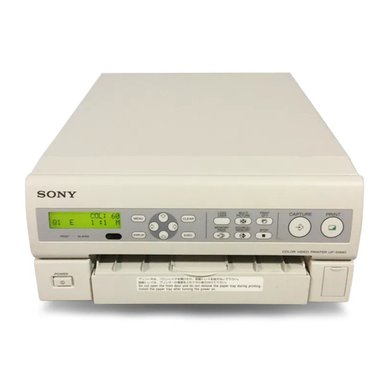
SE-749 board SE-747 board IF-988 board SE-753 board 1-2. Main Parts Location Mechanical main unit assembly DC fans (Head unit) DC motors (Head) Switching regulator Stepping motor DC fan (For inside) DC motors (Ribbon) Ribbon drive assembly Thermal head UP-55MD... -
Page 10: Removing/Installing The Cabinet
(CN805, CN601 and CN602) on CN1001 the MA-142 board. Harnesses 4. Remove the four hooks, then remove the front panel MA-142 BVTT assembly. CN904 2.6 x 5 board 5. Attach the rear panel assembly in the reverse order of steps 1 to 4. UP-55MD... -
Page 11: Replacing The Board
2.6 x 5 W2.3 MA-142 board Flexible flat cables Harnesses Harnesses MEC-24 board 8. Install the MEC-24 board in the reverse order of steps 5. Install the MA-142 board in the reverse order of steps 1 to 7. 1 to 4. UP-55MD... - Page 12 10. Disconnect the flexible flat cable from the connector (CN501) on the KY-582 board. 11. Remove the two screws (BVTP2.6 x 6), then remove the spring (LCD) and DP-407 board. 12. Disconnect the flexible flat cable from the connector (CN407) on the DP-407 board. UP-55MD...
- Page 13 D. Hook [B] 15. Disconnect the harness from the connector on the SE- 750 board. Hook [C] 16. Install the SE-747 board, SE-750 board and SE-752 board in the reverse order of steps 1 to 15. UP-55MD...
-
Page 14: Board
Flexible flat cable BVTT 2.6 x 5 CN108 IF-989 board 8. Install the IF-988 board in the reverse order of steps 1 9. Install the IF-990 and IF-989 boards in the reverse to 7. order of steps 1 to 8. UP-55MD... -
Page 15: Replacing The Main Parts
90 mm or more PS3 x 6 PS3 x 6 Shield plate (A) Protector sheet (A) Switching regulator Harness PS3 x 6 Harnesses 3 x 6 8. Attach the switching regulator in the reverse order of steps 1 to 7. UP-55MD... -
Page 16: Stepping Motor
(R) Tension arm W2.3 assembly Pick-up belt Switching regulator Helical extension BVTT2.6 x 5 BVTT2.6 x 5 spring Tension arm (S) subassembly 10. Attach the mechanical main unit assembly in the reverse order of steps 1 to 9. UP-55MD... - Page 17 Pick-up belt Cam gear (L) Shaft Oblong hole Oblong hole of Hole of cam W2.3 chassis gear (L) Sensor gear 50 mm or more ø2 Shaft 16. Assemble this unit in the reverse order of steps 1 to 5. UP-55MD...
-
Page 18: Ribbon Drive Assembly
Idler gear (R) Limiter (T) 2.6 x 5 Ribbon gear assembly Ribbon drive assembly Harnesses Limiter (S) assembly Supply lock DC motor (ribbon) subassemblies 13. Attach the ribbon drive assembly in the reverse order of steps 1 to 12. 1-10 UP-55MD... -
Page 19: Center Stay Assembly
Ribbon rail (R) Be sure to securely attach the shaft of the pendulum arm to the hole of the center stay assembly. Portion B Portion A BVTT 2.6 x 5 BVTT Front corner stay 2.6 x 5 CCM-53 board 1-11 UP-55MD... -
Page 20: Paper Feed Guide Assembly
A of the paper feed guide assembly into the portions B of the main chassis. W3.0 Bearing Tray rail (L) (850) Helical extension spring Pick-up arm (R) Tray rail (R) BVTT subassembly 2.6 x 5 1-12 UP-55MD... -
Page 21: Dc Fan (Head Unit)
P2.6 x 5 Ribbon sensor mounting plate Eccentric pins Harness Flexible flat cable Mechanical main CN302 CN303 EX-970 board unit assembly Thermal head 9. Attach the two DC fans in the reverse order of steps 1 to 8. 1-13 UP-55MD... -
Page 22: Pinch Roller
Hole Thermal head Hole 12. Attach the pinch roller in the reverse order of steps 10 and 11. 13. Clean the pinch roller with alcohol. 14. Assemble this unit in the reverse order of steps 1 to 9. 1-14 UP-55MD... -
Page 23: Capstan Roller/Platen Roller
21. Clean the capstan roller and platen roller with alcohol. Helical extension 22. Assemble this unit in the reverse order of steps 1 to 10. spring BVTT 2.6 x 5 Platen earth Paper lift lever plates Helical extension subassembly spring 1-15 UP-55MD... -
Page 24: Cam Gear (L)/Cam Gear (R)
13. Remove the retaining ring, then remove the cam gear (L). Mode lever (R) subassembly Check that the bearing is attached to the shaft of the mode lever (L) subassembly. 1-16 UP-55MD... - Page 25 (R). Cam (L) (Black) Outside Inside Imprinting Grease Groove Shaft of mode lever (L) subassembly Cam gear (L) Hole of chassis Cam (R) (White) Bearing Hole Outside Inside Imprinting E3.0 Grease Groove Mode lever (L) subassembly 1-17 UP-55MD...
- Page 26 21. Attach the cam gear (L) and cam gear (R) in the Shaft of mode lever (R) subassembly reverse order of steps 12 to 14 with the cam gear (L) and cam gear (R) secured state. 22. Assemble this unit in the reverse order of steps 1 to 11. 1-18 UP-55MD...
-
Page 27: Interlock Switch
Spare parts are listed in the spare parts list of “Spare Parts” Section (Volume 2). In the spare parts list, (GOLD) or (SILVER) is put after each part name to distinguish two kinds of types (gold and silver). 1-19 UP-55MD... -
Page 28: Recommended Power Cord
For customers in the U.S.A. and Canada: 1 Power cord 125 V 13 A (2.4 m): ! 1-556-813-22 This unit does not come with a power cord. To get a power cord, please contact your local Sony Sales AC inlet Office/Service Center. -
Page 29: Lithium Battery
The KY-582 board is mounted a lithium battery for the clock. The lithium battery is not available as repair parts. When replacing, use a CR2025-type lithium coin battery by Sony. 1. Open the front door. 2. Remove the battery cover using a fine-tipped driver, etc.. -
Page 31: Electrical Alignment
The voltage value of thermal head is adjusted. automatically. Increase the value: The voltage supply to the thermal head is increased and the print density becomes higher. Decrease the value: The voltage supply to the thermal head is decreased and the print density becomes lower. UP-55MD... - Page 32 When carrying out this item, the temperature control of thermal head is not performed. To make the print, press the [PRINT] button of this unit. . STEP(V) . STEP(H) . COLOR BAR(H) . GRAY(C0h) . GRAY(80h) . GRAY(40h) . BLACK UP-55MD...
- Page 33 The time (numeric value) is updated every 15 minutes. SAVE INTG. When the operating time is within 15 minutes, it is not Not used reflected on the numeric value. RBN INFO The information of ribbon installed in this unit is displayed. UP-55MD...
-
Page 34: Thermal Head Replacement Procedure
It is recommended to perform the procedure Be sure to perform the following procedure when replacing with the top cover removed, which saves the time the thermal head. before the printing starts. (For the procedure of removing the top cover, refer to Section 1-3-1.) UP-55MD... -
Page 35: Density Check And Adjustment
[CAPTURE] and [PRINT] buttons simultaneously. 2. Check that “INITIALISE” is displayed on LCD. Even if the master reset is performed, the density adjustment value (HEAD V value), printing position adjustment value (P H SHIFT value) and LANGUAGE setting are not reset. UP-55MD... -
Page 36: Version Upgrade
9. Select the item using the [&] and [*] buttons. . DM179AP.VUP: Select SY. . PNX179AP.VUP: Select VA. . Upgrade the two CPU’s at the same time: Select ALL. (For details, refer to “Upgrading the two CPU’s at the same time”.) UP-55MD... -
Page 37: Restoration Of This Unit
4. Turn on the power of this unit while pressing the switch on the MA-142 board (near the head harness at the center of the S1454 board). The progress status is displayed on the monitor. 5. Check that “END” is displayed on the monitor. UP-55MD... -
Page 39: Troubleshooting
The description of each item in TROUBLE and SENSOR The remaining amount of ribbon loaded in this unit at the is as follows. time of error is displayed. TTL PRINT The total print count of this unit at the time of error is displayed. UP-55MD... -
Page 40: Saving Function To Memory Stick
THRESH HL Threshold voltage H LEVEL REC ID H level voltage The ID number of the past error is displayed. The larger number represents the later error. L LEVEL The whole data can be sorted on Excel. L level voltage UP-55MD... -
Page 41: Error Code Table
HEAD_PRINT_ The head cannot move from the print position on MA-142 board HOME_TIMEOUT to the home position and time-out occurs. 0x0e HEAD_FEED1_ The head cannot move from the paper pick HOME_TIMEOUT position to the home position and time-out occurs. UP-55MD... - Page 42 0x63 PP_JAM_ERR “Paper exist” is detected with the timing of “No paper” in a jamming sensor during paper feed. 0x64 PP_JAM_ “No paper” is detected with the timing of “Paper MISSING_ERR exist” in a jamming sensor during paper feed. UP-55MD...
-
Page 43: Operating Mode (Status)
Install the head block properly. A ribbon rail is damaged. Replace the ribbon rail. A ribbon rail is out of position. Install the ribbon rail properly. A ribbon is not properly installed in the cartridge. Install the ribbon properly in the cartridge. UP-55MD... - Page 44 A head block is not in the prescribed position. Replace the cam, joint gear, or gear. (A cam, joint gear, or gear is defective.) A feed guide assembly is damaged. Replace the feed guide assembly. UP-55MD...
- Page 45 (A cam, joint gear, or gear is defective.) The tension of a ribbon is not proper. Confirm the limiter (T) and (S) assemblies and replace them. Confirm that the supply lock torsion panel is out of position and install it properly. UP-55MD...
- Page 46 A stepping motor is out of order. Apply the tension of a belt again. (The tension of a belt is not proper.) A feed guide assembly is damaged. Replace the feed guide assembly. Dedicated paper is not used. Replace the paper used by dedicated paper. UP-55MD...
- Page 47 An eject flap is out of position and damaged. Replace the eject flap. in spite of paper removal. The SE-752 board is defective. Confirm CN111 on the SE-752 board, CN105 on the MEC-24 board, and the harness. UP-55MD...
-
Page 49: Location And Functions Of Sensors, Motors, And Mechanical Parts
Location and Functions of Sensors, Motors, and Mechanical Parts This section describes the location and functions of sensors, motors, and mechanical parts. Refer to Section 1 for how to remove (replace) parts. Index Item Page 4-1. Sensors and Motors 4-2. Mechanical Parts UP-55MD... -
Page 50: Sensors And Motors
Head cooling fan In-unit cooling fan 4-2. Mechanical Parts Name Name Platen Eject roller Grip roller Ink ribbon Pinch roller Take-up limiter Thermal head Supply limiter Separation pad Ribbon guide Press roller Mode lever Load roller Cam gear UP-55MD... - Page 51 In this separated in certain timing. The supply ribbon is locked case, fixed torque is applied to the take-up and supply and not pulled out. ribbons. Disturbance (load fluctuation) must not occur in paper. UP-55MD...
-
Page 53: Circuit Description
Circuit Description 5-1. Outline of Operation 5-2. Outline of MA-142 Board The electric circuit configuration of UP-55MD (hereinafter The MA-142 board is mainly classified into two circuit blocks. referred to as this unit) can be mainly classified as follows: 1. Video signal processing block 1. - Page 54 Power is regulated to +2.5 V, +1.8 V, and +1.2 V as required and mainly supplied to the peripheral circuits of IC1101. Moreover, power is also supplied from CN201 to the MA- 142 board. UP-55MD...
-
Page 55: Soc (Ic103) Block
IC103, the gradation set in IC103 is operated and expanded to another image memory. An image is transferred during paper feeding of mechanical operation with the timing when data transfer time does not influence the print time. UP-55MD... - Page 56 When the USB flash memory device is connected to a printer, CPU detects the potential of VBUS and generates an interrupt. A dedicated file folder (\SONY\PRINTER\IMAGES) for image saving is searched when a device is recognized. Preparations for image write can be made when a file is recognized.
-
Page 57: Printer-Dedicated Circuit (Ic301)
The other terminal is used for a head clock during print. A clock of 100 MHz generated from a 20 MHz oscillator (X301) and PLL circuit (IC303) is input as an operating clock. Also, the clock generated from a 33 MHz oscillator (X302) is input for a head clock. UP-55MD... - Page 58 PP_F_EDGE Detection of paper front edge PP_B_EDGE Detection of paper back edge RBN_MARK Ribbon mark detection PLTN_TH Thermister in unit PP_IN Presence of paper HADIN REMOTE2_MIN Detection of REMOTE2 input analog level LCD_CONT LCD contrast V_CONT Head power V_CONT UP-55MD...
- Page 59 *2: For the specifications of a head, the data port number of is assigned from 1. Therefore, head data 0 on the IC side is connected to head data 1 on the head side, and head data 19 on the IC side is connected to head data 20 on the head side. UP-55MD...
-
Page 60: Mechanical Control Block
Thermal head temperature detection The voltage that was voltage-divided by the thermister and fixed resistors (R705, R706, and R707) installed in a thermal head is input to the A/D pin of a printer-dedicated circuit so as to detect a temperature. UP-55MD... -
Page 61: Key Input And Liquid-Crystal Display
GND. It is shut down when this control line is opened. This control line is connected to the opening/closing sensor of a bottom plate using a connector (CN203). Power cannot be turned on when the bottom plate is opened. UP-55MD... -
Page 62: Mechanical Control Block
The fan motor rotates when a temperature reaches more than the fixed temperature during print and in the standby state. CN804 +12V ROOM_FAN C841 C842 +3.3V MA-142 R854 Q803 R853 R855 Q802 EX-970 IC301 CN302 +12V HEAD_FAN 0 C205 C206 CN303 HEAD_FAN 1 R214 Q204 R213 R215 Q203 MEC-24 5-10 UP-55MD... - Page 63 R807 R806 IC205 CN203 RESET OUTA1 CW/CCW OUTA2 CLOCK OUTA1 OUTA2 OUTB1 OUTB2 SYNC OUTB1 OUTB2 SENSEA SENSEB TO IC301 99 pin IC207 R220 R222 R224 R226 IC703 C732 C204 C208 R229 R221 R223 R225 R227 MA-142 MEC-24 5-11 UP-55MD...
- Page 64 The two motor drive circuits (IC202 and IC203) on the MEC-24 board are controlled to drive two motors using the control signal at pins 94 and 51 of IC301 on the MA-142 board. +12V IC301 1 (94) OUT1 4 (51) OUT2 SU-86 MA-142 +12V OUT1 OUT2 SU-87 MEC-24 5-12 UP-55MD...
-
Page 65: Sensor Detection Circuits
Head down M print Head up Ribbon C cue-up and paper return Head down C print R114 Q102 R116 R113 R115 CN803/MA-142 16 pin Q101 PH51 PH52 VDR51 VDR52 IC301 R111 R112 C113 C114 GND GND MA-142 MEC-24 SE-746 5-13 UP-55MD... - Page 66 IC301, pin 132 on the MA-142 board H = Paper stack provided. ALARM (LED) lights. L = Paper stack not provided. R114 Q102 R116 R113 R115 CN803/MA-142 16 pin Q101 C106 R111 IC301 PH111 VDR111 C111 C112 R106 C107 MA-142 MEC-24 SE-751 5-14 UP-55MD...
- Page 67 16 pin Q101 MA-142 +2.5V R714 PP_F_EDGE (IC301 174pin) SE-750/749 +2.5V R121 R715 C131 C121 PP_B_EDGE (IC301 87pin) Q131 D121 SE-754/753 +2.5V R716 RBN_MARK (IC301 43pin) SE-747/748 +2.5V R161 R717 C101 C161 PP_IN Q101 D161 (IC301 175pin) SE-751/762 5-15 UP-55MD...
- Page 68 16 pin Q101 MA-142 +2.5V R714 PP_F_EDGE (IC301 174pin) SE-750/749 +2.5V R121 R715 C131 C121 PP_B_EDGE (IC301 87pin) Q131 D121 SE-754/753 +2.5V R716 RBN_MARK (IC301 43pin) SE-747/748 +2.5V R161 R717 C101 C161 PP_IN Q101 D161 (IC301 175pin) SE-751/762 5-16 UP-55MD...
- Page 69 16 pin Q101 MA-142 +2.5V R714 PP_F_EDGE (IC301 174pin) SE-750/749 +2.5V R121 R715 C131 C121 PP_B_EDGE (IC301 87pin) Q131 D121 SE-754/753 +2.5V R716 RBN_MARK (IC301 43pin) SE-747/748 +2.5V R161 R717 C101 C161 PP_IN (IC301 175pin) Q101 D161 SE-751/762 5-17 UP-55MD...
- Page 70 16 pin Q101 MA-142 +2.5V R714 PP_F_EDGE (IC301 174pin) SE-750/749 +2.5V R121 R715 C131 C121 PP_B_EDGE (IC301 87pin) Q131 D121 SE-754/753 +2.5V R716 RBN_MARK (IC301 43pin) SE-747/748 +2.5V R161 R717 C101 C161 PP_IN Q101 D161 (IC301 175pin) SE-751/762 5-18 UP-55MD...
- Page 71 The power of this unit is turned off when a bottom plate is not installed. Level: CN207, pin 7 on the MA-142 board H = Power OFF L = Power ON S141 REMOTE ON/OFF R203 CN201 7pin C203 VDR141 R204 MA-142 SE-755 5-19 UP-55MD...
- Page 73 20 V AC range are suitable. (See Fig. A) To Exposed Metal Parts on Set 0.15 µ F 1.5 k Z voltmeter (5.25V) Earth Ground Fig A. Using an AC voltmeter to check AC leakage. UP-55MD...
- Page 74 Sony Corporation UP-55MD (SY) E 2010. 7 08 9-879-778-03 ©2005...
Need help?
Do you have a question about the UP-55MD and is the answer not in the manual?
Questions and answers