
Related Manuals for Sony UP-25MD


Summary of Contents for Sony UP-25MD
-
Page 1: Instructions For Use
4-162-900-13(1) Color Video Printer Instructions for Use Before operating the unit, please read this manual thoroughly and retain it for future reference. UP-25MD © 2010 Sony Corporation... - Page 2 Record these numbers in the space provided below. device pursuant to Subpart B of Part 15 of FCC Rules. Refer to these numbers whenever you call upon your Sony For the customers in Canada dealer regarding this product.
- Page 3 UP-25MD. Guidance and manufacturer’s declaration-electromagnetic emissions The UP-25MD is intended for use in the electromagnetic environment specified below. The customer or the user of the UP-25MD should assure that it is used in such an environment. Emission test Compliance...
- Page 4 Guidance and manufacturer’s declaration - electromagnetic immunity The UP-25MD is intended for use in the electromagnetic environment specified below. The customer or the user of the UP-25MD should assure that it is used in such as environment. IEC 60601 test...
- Page 5 Guidance and manufacturer’s declaration - electromagnetic immunity The UP-25MD is intended for use in the electromagnetic environment specified below. The customer or the user of the UP-25MD should assure that it is used in such as environment. IEC 60601 test...
- Page 6 Recommended separation distances between portable and mobile RF communications equipment and the UP-25MD The UP-25MD is intended for use in an electromagnetic environment in which radiated RF disturbances are controlled. The customer or the user of the UP-25MD can help prevent electromagnetic interference by maintaining a minimum distance between portable and mobile RF communications equipment (Transmitters) and the UP-25MD as recommended below, according to the maximum output power of the communications equipment.
-
Page 7: Table Of Contents
Adjusting the Printout Color ........ 46 Table of Contents When a Black Frame or Lines Show up on the Printouts ............. 48 Fitting the Printout to the Paper ......49 Adjusting the Color Balance ........ 50 Introduction Specifying Colors for Adjustment (HSV System Overview ............ -
Page 8: Introduction
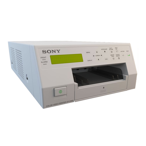
Location and Function of Parts and Controls System Overview Front The UP-25MD is a color video printer that reproduces image inputs from video equipment and other image output devices via simple operations. The UP-25MD has the following features: • High picture quality and high print resolution... - Page 9 N Tray light is pressed. The DISPLAY setting in the OUTPUT SETUP menu also changes in conjunction with each Illuminates the output tray. (You can configure the setting for this.) (page 61) press of this button. When the menu is displayed, pressing this button O Paper feed tray (page 17) temporarily hides the menu display on the monitor.
-
Page 10: Rear
D Media switch lever G - AC IN connector (page 12) Switch the position of this lever according to the type Connects to the power cord. of ink ribbon being used. REMOTE 2 connector (stereo mini jack) (page 14) Rear Connects to an RM-91 Remote Control Unit (not supplied) or an FS-24 Foot Switch (not supplied). - Page 11 G Print quantity display section Urgent messages are displayed on the center of the screen. Indicates the number of copies to be printed. This item blinks while the printer is busy. D S or M (image type) display section H Printer setting status display section Indicates the type of image being displayed on the monitor.
-
Page 12: Preparation
Preparation Connections To enable printing, video equipment to act as an input signal source, and a video monitor to display images or menus must be connected. Supplied Accessories The following diagrams illustrate how to make the input, output and remote control connections. Use this as a guide This printer is packed with the following accessories. -
Page 13: Connecting The Video Monitor
to wall outlet to wall outlet NTSC/PAL NTSC/PAL switch switch AC power cord AC power cord (not supplied) (not supplied) to AC IN to AC IN to VIDEO to RGB/YPbPr/ to VIDEO to RGB/ INPUT SYNC INPUT OUTPUT YPbPr/ SYNC OUTPUT to S VIDEO Connecting... -
Page 14: Making Connections To Enable Remote Control
Making Connections to Enable Remote Control The printer can be controlled remotely by connecting an RM-5500 Remote Control Unit (not supplied), an RM-91 Remote Control Unit (not supplied), an FS-24 Foot Switch (not supplied), or a personal computer. Computer to wall outlet RS-232C cable AC power cord (not supplied) -
Page 15: Operation
2 Switch the position of the media switch lever. Operation UPC-21S/UPC-21L: In UPC-24SA/UPC-24LA: Out Before Printing Once the printer is connected to the computer (page 12), you must load the paper and the ink ribbon as described below before you can actually begin printing. 3 Replace the cover. - Page 16 Load the ink ribbon. Note 1 Align the two pegs on each side of the ink ribbon Do not touch the white tabs on the sides of the ribbon with the slots on the ribbon tray. tray. Doing so may result in improper loading of the ink ribbon.
-
Page 17: Loading The Paper
If the ink ribbon tears during use When using printing packs UPC-21L or Cellophane tape, etc., can be used to repair a torn ink UPC-24LA ribbon so that the remainder of the ribbon can be used. 1 Open the paper feed tray. Cellophane tape Wind the ink ribbon until the cellophane tape is no longer 2 If the paper feed tray partition is raised, lower it. - Page 18 2 If the paper feed tray partition is lowered, raise it. Note Make sure to keep the protective sheet after removing it. The reverse side of the protective sheet (without printing), can be used as a cleaning sheet to clean the thermal head.
-
Page 19: Selecting The Input Signal
Fit the stopper into the two slits on the lid of the paper Select INPUT SEL by pressing the M or m button. feed tray, and insert it all the way in. Highlight INPUT SEL in green by pressing the M or m button. Select the desired input signal by pressing the <... -
Page 20: Making Full-Size Image Printouts
1 Select INPUT FORM. by pressing the M or m Making Full-Size Image button. Highlight INPUT FORM. in green by Printouts pressing the M or m button. This section explains how to make a full-size image printout. The operations described here constitute the basic procedure for making a printout. - Page 21 Start the video source to display the source image on Note the video monitor. This operation is done using the controls of the video Usually, it is recommended that you make printouts in equipment acting as the source. FRAME mode. (The default setting is FRAME.) You can confirm the memory mode setting on the bottom part of the video monitor.
- Page 22 The printing time depends on the print speed settings. To change the printout speed You can select the speed using the PRN SPEED item on On the video monitor, Q display blinks in the color which the PRINTER SETUP menu. is being printed.
-
Page 23: Making Printouts With The Desired User Set Number
Select the desired user number by pressing the < or Making Printouts with the Desired , button. User Set Number Highlight the desired user number in green by You can register all the printer settings as a user settings. pressing the < or , button. The user name of the selected user number appears below. - Page 24 To set the printout quantity by using the PRINT To decrease the number of copies QTY button While the screen which appears in step 1 is displayed, press the < button. Each time you press the < button, the number decreases. When the number reaches 1, if the 1, 2 <...
-
Page 25: Capturing Another Image While Printing
If the paper runs out during printing Press the PRINT button. The image captured in step 2 is queued. The image is The printer stops the printing operation. printed as soon as all previous printing jobs have been Load the paper into the paper tray and press the PRINT completed. -
Page 26: Making Variations Of Printouts
Selecting the Memory Mode Making Variations of Printouts Frame mode/field mode To make printouts, it is first necessary to capture the image You can capture various kinds of images in memory and in memory. make variations of printouts using the images captured in When capturing an image, there are two ways to use the memory. - Page 27 Field mode: A memory area is divided into two, and Press the MENU button and display the LAYOUT images can be captured in each. In this way a quickly SETUP menu by pressing the < or , button. moving subject can be printed with less blurring. Highlight LAY in green by pressing the <...
-
Page 28: Selecting A Memory Page
Press the MENU button. Press the MEMORY PAGE button repeatedly until the The normal screen appears. desired memory page appears. Selecting a Memory Page Memory page A memory area in which an image is captured is called a memory page in this manual. The number of usable memory pages depends on the type of the reduced images selected and on the memory mode. -
Page 29: Making A Printout Of Multiple Different Reduced Images
Making a Printout of Multiple Different Reduced Images You can capture multiple images in a memory page and make a printout with those reduced images. This section explains how to make a printout with multiple reduced The currently selected type of reduced images. - Page 30 Select the type of reduced images to be captured in The FUNCTION SETUP menu appears. memory by pressing the < or , button. Select AUTO LIVE by pressing the M or m button. Highlight the type of reduced images to be captured in memory in green by pressing the <...
- Page 31 • Select whether the white borders are to be added. (See display in step 1. The green blinking star (referred to page 32.) as the cursor) on the video monitor moves to the next The white border setting for printouts of four reduced position and the number on the printer window images can be made before or after the four images are display advances by 1.
- Page 32 Pressing the M, m, < or , button moves the Note cursor one position by one position vertically or horizontally. This setting is also effective for the images which have been captured. Press the M, m, < or , button until the third cursor blinks green.
-
Page 33: Making Printouts With A Caption
Non-text caption entry operations Making Printouts with a Display in the Function Caption CAPTION menu Inserts one character without erasing the highlighted character. Deletes a highlighted character and characters Making Printouts With a Caption shift back by one. A caption, such as comments, can be added to a printout Puts one space at the position of the below the image. - Page 34 Select CAPTION by pressing the M or m button. Select the character you want to enter by pressing the M, m, < or , button. Highlight CAPTION in green by pressing the M or m button. Example: Enter S. Highlight S in green by pressing the M, m, < or , button.
- Page 35 Press the EXEC button. To replace a previously entered character The character selected in step 5 appears at the point without changing the number of characters where the green cursor is positioned in the character You can replace a previously entered character with a display area, after which the cursor moves to the next new one.
-
Page 36: Deleting Images Stored In Memory
Set the CAPTION ON/OFF function to ON. Deleting Images Stored in 1 Select ON by pressing the M, m, < or , button. Memory You can use the STOP/CLEAR button to delete individual reduced images captured to a memory page, or to delete all of the images from one or all of the memory pages. -
Page 37: Deleting Images Stored In Memory
Deleting images in a certain memory page When you want to Settings Before deleting images Delete images of all memory pages. Set CLEAR to PAGE in the FUNCTION SETUP menu. Delete images of a single memory page. PAGE Delete the reduced image. PART Disable functioning as the CLEAR button. -
Page 38: Erasing The Screen Display On The Video Monitor
Press the SOURCE/MEMORY button when the Erasing the Screen source image is displayed on the video monitor. The image captured in memory is displayed on the Display on the Video screen. Monitor Select the memory page from which the reduced image is to be deleted by pressing the MEMORY You can erase characters displayed on the video monitor PAGE button. - Page 39 Each time you press the DISPLAY button, the setting changes in the following sequence: ON t OFF t ON..Highlight OFF in green. To display characters on the video monitor Select ON. To set the monitor display from the menu You can also set whether characters are displayed on the video monitor by changing DISPLAY to ON or OFF in the OUTPUT SETUP menu.
-
Page 40: Adjustment
Menu Functions to be set Reference Adjustment pages FUNCTION Selecting the image which SETUP appears after storing the image into memory, the source image or the memory Functions That Can be image Assigning the function to Set on Menus remote control units connected to the REMOTE 2 connector You can set up the printer to meet various specifications. -
Page 41: Menu Tree
Menu Tree Normal screen COLOR ADJUST menu WINDOW SETUP menu Press the MENU button. LAYOUT SETUP menu CAPTION menu For reference pages of each menu, see the table on “Functions That Can be Set on Menus” on page 40. PRINTER SETUP menu SYSTEM SETUP menu USER NAME menu INPUT SETUP menu... -
Page 42: Basic Menu Operations
When the cursor (that is highlighted in green) Basic Menu Operations is not positioned on the top line: Move the cursor to the top line by pressing the M or m button. In this section, in addition to the video monitor, the printer window display is also introduced. - Page 43 Select the desired item by pressing the M or m button. When - - - - - is displayed at the selection: - - - - - is displayed when changing the selection is Example: To select PRN SPEED on the ineffective.
- Page 44 To change the setting values: To return from the sub menu: Press the < or , button to decrease or increase the Select the menu on the top line, then press the , setting values. button. The current setting value Highlight PRN SETUP in green by pressing the M or m button, then press the , button.
-
Page 45: Adjusting The Color And Picture Quality
NTSC and PAL composite video signal or a separated luminance (Y) and chrominance (C) signal. Adjusting the Color and b) On a setting of step –14, OFF appears and the image, displayed on the video monitor, becomes black and white. Picture Quality c) When a component (RGB or YPbPr signal) signal is input, you cannot adjust OFFSET below 0. -
Page 46: Adjusting The Printout Color
Adjustment on the video monitor Menu When you Button to Adjustment The monitor color may not be adjusted correctly even if the adjustment want to direction on item pressed the menu printer color is correctly adjusted. Check the color of the (Adjustment video monitor before adjusting the printout color. - Page 47 Perform the adjustments while viewing the images To adjust the color intensity (RED/GREEN/ captured in memory. BLUE) The RED, GREEN and BLUE color component Display the COLOR ADJUST menu. settings are divided into 15 steps, from –7 to +7, indicated by a value and graph. The center of the COLOR ADJUST menu graph (0) corresponds to the standard setting.
-
Page 48: When A Black Frame Or Lines Show Up On The Printouts
Once you have changed the value Adjusting the tone of the printout Once you have changed the value, TEMP You can adjust the tone so that the details in the white or (TEMPORARY) appears on the menu screen. TEMP black part are clearly printed. indicates that the settings are temporary and have not yet been stored. -
Page 49: Fitting The Printout To The Paper
Perform adjustments according to the printout Note obtained by using the V START, V WIDTH, H START and H WIDTH items. A black line may apper on the right side while you adjusting on the left side. You can eliminate it using Item to be used for eliminating the vertical the H WIDTH item. -
Page 50: Adjusting The Color Balance
Select RESIZE TO FIT. Display the COLOR BALANCE menu from the PRINTER SETUP menu. Highlight RESIZE TO FIT in green. Select C-BALANCE, then press the , button. Setting When you want to The COLOR BALANCE menu appears. The highlighted area on the COLOR BALANCE menu Print the image with the printout area will be printed to be used for adjusting the color adjusted on the WINDOW SETUP... - Page 51 To reset the values to the factory setting (50/ This print operation can also be performed by 50/5) pressing the PRINT button while the COLOR Select each item by pressing the M or m button, then BALANCE menu is displayed. press the <...
-
Page 52: Specifying Colors For Adjustment (Hsv Adjustment)
The color balance of the printed image has been adjusted To perform broad adjustment to the values selected in step 5. To perform color balance adjustment beyond the current color balance range, increase the value of To readjust the color balance BAL STEP. - Page 53 Decide the position of the source image to be used for Note HSV adjustment. If grayscale data is changed due to COLOR ADJUST To decide the position of the source image, move the highlighted area by pressing the M, m, < or , menu and color balance adjustments, the adjustments of this function may affect the picture quality.
- Page 54 Specify the step setting. COLOR SEL Description Specify the step setting with STEP. GRN [G-C] Specifies green for adjustment. When adjusting the INTENSITY, the hues between green and cyan (G-C) are specified. CYN [C-B] Specifies cyan for adjustment. When adjusting the INTENSITY, the hues between cyan and blue (C-B) are specified.
- Page 55 H = HUE value of specified color Parameter Description The changes in the parameter specified with SPLIT9 INTENSITY Adjusts the hue of the color range that appear in the test print are as follows. (ex: [R-Y]) selected with COLOR SEL. If RED [R-Y] is selected for COLOR SEL, for example, the hue of colors between red and yellow is more red...
- Page 56 To reset the values to the factory setting To perform broad adjustment Select each item with the cursor, then press the < To perform parameter adjustment beyond the current and , buttons at the same time. parameter range, increase the current STEP value. As data is stored separately for each COLOR SEL color, be sure to perform the above procedure for each COLOR SEL color if you want to reset all the...
-
Page 57: Configuring Hdtv-Signal Inputs And Outputs
Select SD/HD SEL by pressing the M or m button, and Configuring HDTV-Signal select the input signal type for printing by pressing the < or , button. Inputs and Outputs Highlight the desired input signal type in green by pressing the < or , button. Selecting the Input Signal Select the input signal based on the input connector being used to connect the video equipment. -
Page 58: Selecting The Synchronization Method For Input Signals
Select HD FORMAT by pressing the M or m button, Selecting the Output Signal Type and select the HDTV signal format by pressing the < or , button. With HDTV signal input, you can select whether the printer outputs signals to a video monitor unchanged or Highlight the desired format in green by converts them to SDTV signals. -
Page 59: Selecting The Downconvert Method
Squeeze: Compresses the HDTV image horizontally into Selecting the Downconvert Method 4:3 aspect ratio. The entire HDTV image is output, but When downconverting HDTV signals for output as SDTV objects appear vertically stretched. signals, select the downconverting method. Original Image resolution is reduced and the aspect ratio changes to 4:3 when you downconvert the signals. -
Page 60: Making Various Settings
Function to be Operation Making Various Settings assigned CAP-STOP Each press of the switch captures (CAPTURE STOP) an image to memory. When the last memory page is reached, the “HIT Assigning Functions to the Remote ANY KEY” message appears and image capturing is disabled. -
Page 61: Adjusting The Contrast Of The Printer Window Display
b) When multiple reduced images are being captured, after the last image is captured, the printer goes to the next Function Setting (abbreviated memory page. display/display when selected) The tray light shines for M1/MODE1 Adjusting the Contrast of the Printer approx. -
Page 62: Setting The Baud Rate
Display the ink ribbon type and remaining the printer’s RS-232C connector, select the appropriate amount. baud rate. For details, contact your nearest Sony dealer. Erase the information about the ink ribbon type and remaining amount. Display the SYSTEM SETUP menu from the PRINTER SETUP menu. - Page 63 Select the USER NAME item, then press the , Select 2 from the SAVE USER item on the SYSTEM button. SETUP menu. The USER NAME menu appears. Press the EXEC button. The set values, modified in step 3, are registered as user set 2.
-
Page 64: Miscellaneous
2 Simultaneously press <, ,, and the MENU Miscellaneous button. The printer operation sound continues for approximately 4 seconds, and the message “PLEASE WAIT” appears on the printer window display. Precautions 3 When the printer operation sound stops and the message “TRANSPORT MODE”... -
Page 65: Cleaning The Thermal Head And The Internal Rollers
When the cabinet becomes dirty Load the thermal head cleaning cartridge into the printer. Clean the cabinet, panel and controls with a soft dry cloth, When an ink ribbon is loaded in the printer, remove it or a soft cloth lightly moistened with a mild detergent before loading the thermal head cleaning cartridge. -
Page 66: Ink Ribbon And Paper
Notes for preserving your printouts Ink Ribbon and Paper • Keep printouts in a dark and cool place. • Be sure not to stick plastic tape onto the printout. Also avoid leaving a plastic eraser on top of the printout or Do not re-use putting the printout between objects which contain Doing so may result in malfunction and negatively... -
Page 67: Specifications
Output connectors RGB/YPbPr (BNC × 3): Specifications 0.7 Vp-p SYNC ON G: 0.3 Vp-p, sync negative Power requirements SYNC (BNC × 1) 100 to 240 V AC, 50/60 Hz 0.3 to 4 Vp-p, sync negative Input current 1.7 to 1.0 A S VIDEO (4-pin mini-DIN ×... - Page 68 CAPTURE timing pulse for REMOTE 2: SOFTWARE, EXTERNAL STORAGE, OR OTHER REMOTE 2 connector pin assignment: EXTERNAL DEVICE. • SONY WILL NOT BE LIABLE FOR DAMAGES OF ANY KIND INCLUDING, BUT NOT LIMITED TO, COMPENSATION OR REIMBURSEMENT ON ACCOUNT OF THE LOSS OF PRESENT OR...
-
Page 69: Troubleshooting
• The paper is not loaded correctly. Should the problem persist after you have applied the tCheck which side of the paper remedy, unplug the unit and contact your Sony dealer or is the printing side, then load local authorized Sony service facility. - Page 70 Symptom Possible causes and remedies The printer ejects a blank The ink ribbon has been used up. tReplace the ink ribbon (page 15). sheet of paper, and then the ALARM indicator Do not reuse the ejected paper. lights and the message “CHANGE RIBBON”...
-
Page 71: Error/Warning Messages
• The ink ribbon has torn. tRepair the torn ink ribbon. (See page 17.) • When this message appears even though the ink ribbon is not torn, contact your Sony service facility or your Sony dealer to clear the error status. Error/Warning Messages... -
Page 72: Warning Messages
MECHA TROUBLE nn The thermal head is malfunctioning. HEAD tTurn the printer off, and then on again. If the error message persists, consult your Sony dealer. MECHA TROUBLE:TEMP nn MECHA TROUBLE nn The internal temperature of the printer is abnormal. - Page 73 Warning message Possible causes and remedies On the video monitor On the printer window display PLEASE WAIT PLEASE WAIT In the selected memory page, the captured image is being printed PRINTING MEMORY PRINTING MEMORY or queued. tRetry the operation once the printer finishes printing. PLEASE WAIT PLEASE WAIT The temperature of the thermal head is being adjusted.
-
Page 74: Clearing A Paper Jam
Load the paper properly. Clearing a Paper Jam If the ALARM indicator on the ribbon door panel lights after printing starts, or if the “REMOVE PAPER” or “CHECK PAPER” message appears on the printer window display, a paper jam may have occurred inside the printer. If the message does not disappear after removing the paper feed tray and reinserting it with paper loaded inside, perform the following to clear the jammed paper. - Page 75 Lift up the base plate and remove it from the printer. Note Carefully clear the jammed paper. The printer cannot print with the base plate removed. If a paper jam still cannot be cleared Consult your Sony dealer. Do not attempt to remove the paper by force. Error/Warning Messages...
- Page 76 Sony Corporation...
Need help?
Do you have a question about the UP-25MD and is the answer not in the manual?
Questions and answers