
Related Manuals for Vega VEGABAR 39


Summary of Contents for Vega VEGABAR 39
- Page 1 Operating Instructions Pressure sensor with metallic measuring cell VEGABAR 39 Three-wire 1 x transistor or 4 … 20 mA Document ID: 57536...
-
Page 2: Table Of Contents
Sensor parameter adjustment ..................41 Setup with PC/notebook (Bluetooth) ................... 42 Preparations ........................42 Connecting ........................42 Parameter adjustment ....................43 10 Diagnostics and servicing ....................45 10.1 Maintenance ........................45 VEGABAR 39 • Three-wire 1 x transistor or 4 … 20 mA... - Page 3 Safety instructions for Ex areas Take note of the Ex specific safety instructions for Ex applications. These instructions are attached as documents to each instrument with Ex approval and are part of the operating instructions. Editing status: 2020-08-31 VEGABAR 39 • Three-wire 1 x transistor or 4 … 20 mA...
-
Page 4: About This Document
Sequence of actions Numbers set in front indicate successive steps in a procedure. Battery disposal This symbol indicates special information about the disposal of bat- teries and accumulators. VEGABAR 39 • Three-wire 1 x transistor or 4 … 20 mA... -
Page 5: For Your Safety
Installation and operation in the USA and Canada This information is only valid for USA and Canada. Hence the follow- ing text is only available in the English language. VEGABAR 39 • Three-wire 1 x transistor or 4 … 20 mA... - Page 6 Installations in the US shall comply with the relevant requirements of the National Electrical Code (ANSI/NFPA 70). Installations in Canada shall comply with the relevant requirements of the Canadian Electrical Code. VEGABAR 39 • Three-wire 1 x transistor or 4 … 20 mA...
-
Page 7: Product Description
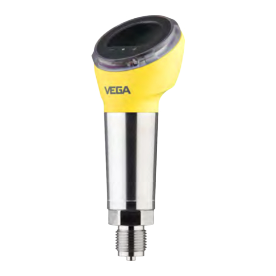
The respective scope of delivery results from the order specification. Scope of this operating This operating instructions manual applies to the following instrument instructions versions: • Hardware version from 1.0.0 • Software version from 1.2.0 VEGABAR 39 • Three-wire 1 x transistor or 4 … 20 mA... - Page 8 Constituent parts Fig. 1: Components of VEGABAR 39 1 Process fitting Electronics housing Ventilation/pressure compensation Plug connector LED illuminated ring Display/adjustment unit The type label contains the most important data for identification and Type label use of the instrument. VEGABAR 39 • Three-wire 1 x transistor or 4 … 20 mA...
-
Page 9: Principle Of Operation
Enter serial number manually in the VEGA Tools app (available free of charge in the respective stores) Principle of operation Application area VEGABAR 39 is suitable for applications in virtually all industries. It is used for the measurement of the following pressure types. • Gauge pressure •... - Page 10 Sensor element Base element Transmission liquid Process diaphragm Strain gauge (DMS) sensor element For measuring ranges above 250 bar, a strain gauge (DMS) sensor element (dry system) is used. VEGABAR 39 • Three-wire 1 x transistor or 4 … 20 mA...
-
Page 11: Adjustment
Wireless adjustment Devices with integrated Bluetooth module can be adjusted wirelessly via standard adjustment tools: • Smartphone/tablet (iOS or Android operating system) • PC/notebook (Windows operating system) VEGABAR 39 • Three-wire 1 x transistor or 4 … 20 mA... -
Page 12: Packaging, Transport And Storage
Protected against solar radiation • Avoiding mechanical shock and vibration • Storage and transport Storage and transport temperature see chapter " Supplement - temperature Technical data - Ambient conditions" VEGABAR 39 • Three-wire 1 x transistor or 4 … 20 mA... -
Page 13: Accessories
Threaded adapters enable simple adaptation of devices with stand- ard threaded fittings, e.g. to process-side hygiene connections. Mounting accessories The suitable mounting accessories for VEGABAR 39 includes si- phons, blocking valves and measuring instrument holders. VEGABAR 39 • Three-wire 1 x transistor or 4 … 20 mA... -
Page 14: Mounting
Use a suitable connection cable (see chapter "Connecting to power supply") • Tighten the cable gland or plug connector • When mounting horizontally, rotate the housing so that the cable gland or plug connector point downward VEGABAR 39 • Three-wire 1 x transistor or 4 … 20 mA... - Page 15 Higher process temperatures often mean also higher ambient temperatures. Make sure that the upper temperature limits stated in chapter "Technical data" for the environment of the electronics hous- ing and connection cable are not exceeded. VEGABAR 39 • Three-wire 1 x transistor or 4 … 20 mA...
-
Page 16: Process Pressure Measurement
Mount the instrument above the measuring point Possible condensation can then drain off into the process line. Fig. 9: Measurement setup for process pressure measurement of gases in pipelines VEGABAR 39 Blocking valve Pipeline In vapours Keep the following in mind when setting up the measuring system: • Connect via a siphon VEGABAR 39 • Three-wire 1 x transistor or 4 … 20 mA... - Page 17 Keep the following in mind when setting up the measuring system: • Mount the instrument below the measuring point The effective pressure line is always filled with liquid and gas bubbles can bubble up to the process line. Fig. 11: Measurement setup for process pressure measurement of liquids in pipelines VEGABAR 39 Blocking valve Pipeline VEGABAR 39 • Three-wire 1 x transistor or 4 … 20 mA...
-
Page 18: Level Measurement
Keep the following in mind when setting up the measuring system: • Mount the instrument below the min. level • Do not mount the instrument close to the filling stream or emptying area • Mount the instrument so that it is protected against pressure shocks from the stirrer Fig. 12: Measurement setup for level measurement VEGABAR 39 • Three-wire 1 x transistor or 4 … 20 mA... -
Page 19: Connecting To Power Supply
1. Loosen the screw on the rear of the plug connector 2. Remove the plug connector and seal from VEGABAR 39 3. Remove the plug insert from the plug housing VEGABAR 39 • Three-wire 1 x transistor or 4 … 20 mA... - Page 20 Plug insert Plug seal 7. Snap the plug insert into the plug housing and insert the sensor seal 8. Plug the plug insert with seal to VEGABAR 39 and tighten the screw The electrical connection is finished. ISO 4400 plug with Proceed as follows: hinged cover 1.
- Page 21 10. Hook in the cover and push onto the plug connection, tighten cover screw 11. Plug the plug insert with seal to VEGABAR 39 and tighten the screw VEGABAR 39 • Three-wire 1 x transistor or 4 … 20 mA...
-
Page 22: Wiring Plan
Fig. 18: Wiring plan - Three-wire 1 x transistor or 4 … 20 mA Voltage supply PNP switching NPN switching Current output Contact, plug connector Function/Polarity Voltage supply/Plus Voltage supply/Minus Transistor or current output Galvanically connected to the housing VEGABAR 39 • Three-wire 1 x transistor or 4 … 20 mA... -
Page 23: Switch-On Phase
The output signal jumps to the set fault current • Switching outputs are controlled The current measured value is then output on the signal cable. With current output activated VEGABAR 39 • Three-wire 1 x transistor or 4 … 20 mA... -
Page 24: Access Protection
If this document is lost, the emergency device code can be retrieved from your personal contact person after legitimation. The storage and transmission of the device codes is always encrypt- ed (SHA 256 algorithm). VEGABAR 39 • Three-wire 1 x transistor or 4 … 20 mA... -
Page 25: Storing The Codes In Myvega
" PINs and Codes". This greatly simplifies the use of additional adjust- ment tools, as all Bluetooth access and device codes are automati- cally synchronized when connected to the " myVEGA" account VEGABAR 39 • Three-wire 1 x transistor or 4 … 20 mA... -
Page 26: Set Up With The Integrated Display And Adjustment Unit
Switching between the individual measured value windows Navigation in the menu items, backwards Change parameter values downwards [+] and [-] Jump to next higher menu simultane- Interrupt input ously VEGABAR 39 • Three-wire 1 x transistor or 4 … 20 mA... -
Page 27: Measured Value And Menu Image Display
The menu items are displayed according to the following diagram: 0.3000 bar Schaltpunkt Ausgang 1 Fig. 21: Display menu item (example) 1 Menu item code acc. to VDMA 24574-1 Actual parameter value 3 Menu item name VEGABAR 39 • Three-wire 1 x transistor or 4 … 20 mA... -
Page 28: Menu Overview
Device-specific access code Protection of the parameterization Deactivated Reset Diagnostics Menu item Code acc. to Delivery status VDMA 24574-1 Status % values outputs referring to nominal measuring range VEGABAR 39 • Three-wire 1 x transistor or 4 … 20 mA... -
Page 29: Parameter Adjustment
Fig. 22: Hysteresis function If the measured variable moves between switching and reset point, the state of the output does not change. VEGABAR 39 • Three-wire 1 x transistor or 4 … 20 mA... - Page 30 If the measured variable moves within the window, the state of the output does not change. Menu item code: • • • • Parameter: • Pressure value Zero The menu item Zero (initial value) defines the pressure value at the output current 4 mA. VEGABAR 39 • Three-wire 1 x transistor or 4 … 20 mA...
- Page 31 These menu items allow access to the menu areas "Extended func- diagnosis tions" or "Diagnosis". Menu item code: • • 7.4.2 Extended functions Damping To damp process-dependent measured value fluctuations, set an integration time in this menu item. VEGABAR 39 • Three-wire 1 x transistor or 4 … 20 mA...
- Page 32 (see chapter "Wiring plan"). Menu item code: • Parameter: • • Function outputs In this menu item the function of the signal outputs is defined. Plug according to ISO 4400: • One transistor output or • One 4 … 20 mA output VEGABAR 39 • Three-wire 1 x transistor or 4 … 20 mA...
- Page 33 If the measured value falls below the lower value of the window again after this time has elapsed, the state of the output does not change. VEGABAR 39 • Three-wire 1 x transistor or 4 … 20 mA...
- Page 34 In this menu item ( live adjustment ) you can accept the current meas- ured value as the value for the 4 mA adjustment (LRV) or the 20 mA adjustment (URV). LRV: Lower Range Value, URV: Upper Range Value VEGABAR 39 • Three-wire 1 x transistor or 4 … 20 mA...
- Page 35 20 % • … • 100 % Pressure unit In this menu item the adjustment unit of the device is defined. The se- lection made determines the displayed unit in the menu items "Zero/ Span" and "Offset correction" as well as "Accept value". VEGABAR 39 • Three-wire 1 x transistor or 4 … 20 mA...
- Page 36 Bluetooth unlock code on the information sheet "Emergency unlock codes" also supplied. Menu item code: • VEGABAR 39 • Three-wire 1 x transistor or 4 … 20 mA...
- Page 37 (see chapter "Menu overview") Menu item code: • Parameter: • Basic settings Language and Bluetooth access code are not reset. VEGABAR 39 • Three-wire 1 x transistor or 4 … 20 mA...
- Page 38 In this menu item, the min. and max. values for pressure, measuring cell temperature and electronics temperature are displayed. Menu item code: • Parameter delivery status only available with a parameter adjustment that deviates from the basic settings, e.g. customer-specific adjustment VEGABAR 39 • Three-wire 1 x transistor or 4 … 20 mA...
- Page 39 Parameter: • Numerical value for pressure or current • Open or closed for switching output Note: Without manual deactivation, the sensor terminates the simulation automatically after 60 minutes. VEGABAR 39 • Three-wire 1 x transistor or 4 … 20 mA...
-
Page 40: Setup With Smartphone/Tablet (Bluetooth)
Operating system: Android 5.1 or newer • Bluetooth 4.0 LE or newer Download the VEGA Tools app from the " Apple App Store", " Goog- le Play Store" or " Baidu Store" to your smartphone or tablet. Device activated Make sure that the VEGABAR 39 is activated, see chapter " Operat- ing modus, activate device". -
Page 41: Sensor Parameter Adjustment
Display", " Diagnosis" and others. The selected menu item, recognisable by the colour change, is dis- played in the right half. Fig. 27: Example of an app view - Setup measured values VEGABAR 39 • Three-wire 1 x transistor or 4 … 20 mA... -
Page 42: Setup With Pc/Notebook (Bluetooth)
After activating the integrated Bluetooth or the Bluetooth USB adapt- er, devices with Bluetooth are found and created in the project tree. Device activated Make sure that the VEGABAR 39 is activated, see chapter " Operat- ing modus, activate device". Connecting... -
Page 43: Parameter Adjustment
DTMs are compiled in a DTM Collec- tion. The DTMs can also be integrated into other frame applications according to FDT standard. VEGABAR 39 • Three-wire 1 x transistor or 4 … 20 mA... - Page 44 9 Setup with PC/notebook (Bluetooth) Fig. 29: Example of a DTM view - Adjustment current output VEGABAR 39 • Three-wire 1 x transistor or 4 … 20 mA...
-
Page 45: Diagnostics And Servicing
Should these measures not be successful, please call in urgent cases the VEGA service hotline under the phone no. +49 1805 858550. The hotline is also available outside normal working hours, seven days a week around the clock. VEGABAR 39 • Three-wire 1 x transistor or 4 … 20 mA... -
Page 46: Diagnosis, Fault Messages
" Diagnostics" via the respective adjustment module. Adjustable via VEGA Tools app or PACTware/DTM VEGABAR 39 • Three-wire 1 x transistor or 4 … 20 mA... - Page 47 Adjustment not within specification Change adjustment Adjustment span too small F036 Failed or interrupted software update Repeat software update no operable sensor software F080 General software error Restart General software error VEGABAR 39 • Three-wire 1 x transistor or 4 … 20 mA...
-
Page 48: Software Update
10.5 Software update The device software is updated via Bluetooth. The following components are required: • Instrument • Voltage supply • PC/notebook with PACTware/DTM and Bluetooth USB adapter VEGABAR 39 • Three-wire 1 x transistor or 4 … 20 mA... -
Page 49: How To Proceed If A Repair Is Necessary
Attach the completed form and, if need be, also a safety data sheet outside on the packaging • Ask the agency serving you to get the address for the return ship- ment. You can find the agency on our homepage. VEGABAR 39 • Three-wire 1 x transistor or 4 … 20 mA... -
Page 50: Dismount
11.2 Disposal The device is made of recyclable materials. For this reason, it should be disposed of by a specialist recycling company. Observe the ap- plicable national regulations. VEGABAR 39 • Three-wire 1 x transistor or 4 … 20 mA... -
Page 51: Certificates And Approvals
NE 43 – Signal level for fault information from measuring transduc- Exception: Versions with measuring ranges from 250 bar. These are subject of the EU Pressure Device Directive. VEGABAR 39 • Three-wire 1 x transistor or 4 … 20 mA... -
Page 52: Environment Management System
" Packaging, transport and Lagestoragerung", " Disposal" of these operating instructions. VEGABAR 39 • Three-wire 1 x transistor or 4 … 20 mA... -
Page 53: Supplement
5/10 Nm (3.688/7.376 lbf ft) Ʋ Varivent 20 Nm (14.75 lbf ft) Transmission liquid with measuring ranges up to 40 bar. With measuring ranges from 100 bar dry measuring cell. VEGABAR 39 • Three-wire 1 x transistor or 4 … 20 mA... - Page 54 0 … 10 bar/0 … 1000 kPa +40 bar/+4000 kPa 0 bar abs. 0 … 25 bar/0 … 2500 kPa +120 bar/+12 MPa 0 bar abs. Data on overload capability apply for reference temperature. VEGABAR 39 • Three-wire 1 x transistor or 4 … 20 mA...
- Page 55 Output variable - three-wire 4 … 20 mA Output signal 4 … 20 mA (active) Connection technology Three-wire Range of the output signal 3.8 … 20.5 mA (default setting) Signal resolution 5 µA VEGABAR 39 • Three-wire 1 x transistor or 4 … 20 mA...
- Page 56 Step response time (ti: 0 s, 10 … 90 %) ≤ 4 ms Reaction time transistor output with ≤ 10 ms switching relevant change of the process variable total Depending on medium and temperature VEGABAR 39 • Three-wire 1 x transistor or 4 … 20 mA...
- Page 57 20°C 100°C -1,2 % Fig. 32: Temperature error with TD 1 : 1 Long-term stability (according to DIN 16086) Specifications refer to the set span. Turn down (TD) is the ratio: nominal measuring range/set span. 0 … +100 °C (+32 … +212 °F) VEGABAR 39 • Three-wire 1 x transistor or 4 … 20 mA...
- Page 58 0 °C (32 °F) 110 °C 130 °C (230 °F) (266 °F) Fig. 33: Temperature derating VEGABAR 39 Process temperature Ambient temperature Relative humidity 20 … 85 % VEGABAR 39 • Three-wire 1 x transistor or 4 … 20 mA...
- Page 59 -40 … +130 °C (-40 … +266 °F) Resolution < 0.2 K SIP = Sterilization in place CIP = Cleaning in place MWP: Maximum Working Pressure Measuring ranges up to 100bar/10 MPa VEGABAR 39 • Three-wire 1 x transistor or 4 … 20 mA...
- Page 60 Reverse voltage protection Integrated Depending on the instrument version Depending on the local conditions = 35 V DC, output signal = 20 mA Load current = 250 mA VEGABAR 39 • Three-wire 1 x transistor or 4 … 20 mA...
-
Page 61: Dimensions
Connection technology 35 mm 40 mm (1.38") (1.57") Fig. 35: Connection technology VEGABAR 39 Plug connector according to ISO 4400 Plug connector according to ISO 4400 with hinged cover VEGABAR 39 • Three-wire 1 x transistor or 4 … 20 mA... - Page 62 DU Thread G½ (EN 837), manometer connection C2 Thread M20 x 1.5 (EN 837), manometer connection LF Thread ½ NPT, inside ¼ NPT (ASME B1.20.1) TI Thread ¼ NPT (ASME B1.20.1) CS Thread G½, inside G¼ (ISO 228-1), Duplex (1.4462) DQ Thread G½, inside G¼ (ISO 228-1), PVDF VEGABAR 39 • Three-wire 1 x transistor or 4 … 20 mA...
- Page 63 ( 2.17 ") ( 2.17 ") Fig. 37: VEGABAR 39, threaded fitting front-flush C3 Thread G½ (ISO 228-1) N9 Thread G¾ (DIN 3852-E) C5 Thread G1 (ISO 228-1) DA Thread G1½ (DIN 3852-A) C9 Thread 1½ NPT (ASME B1.20.1) VEGABAR 39 • Three-wire 1 x transistor or 4 … 20 mA...
- Page 64 ø 40 mm ø 40 mm ( 1.57 ") ( 1.57 ") Fig. 38: VEGABAR 39, cone/extension fitting DH Thread G1 (ISO 228-1), cone 40° LX Thread G1 (ISO 228-1), hygienic design AL Thread M30 x 1.5 (DIN 13) VEGABAR 39 • Three-wire 1 x transistor or 4 … 20 mA...
- Page 65 E7 Ingold connection PN 10 FR Varivent N50-40 PN 25 EZ Collar socket DN 40 PN 40 (DIN 11851) E2 Collar socket DN 40 PN 40 (DIN 11864-1, Form A) VEGABAR 39 • Three-wire 1 x transistor or 4 … 20 mA...
-
Page 66: Industrial Property Rights
Les lignes de produits VEGA sont globalement protégées par des droits de propriété intellec- tuelle. Pour plus d'informations, on pourra se référer au site www.vega.com. VEGA lineas de productos están protegidas por los derechos en el campo de la propiedad indus- trial. Para mayor información revise la pagina web www.vega.com. - Page 67 Notes VEGABAR 39 • Three-wire 1 x transistor or 4 … 20 mA...
- Page 68 Subject to change without prior notice © VEGA Grieshaber KG, Schiltach/Germany 2020 VEGA Grieshaber KG Phone +49 7836 50-0 Am Hohenstein 113...
Need help?
Do you have a question about the VEGABAR 39 and is the answer not in the manual?
Questions and answers