Vega VEGABAR 38 Operating Instructions Manual
Pressure sensor with ceramic measuring cell
Hide thumbs
Also See for VEGABAR 38:
- Operating instructions manual (68 pages) ,
- Operating instructions manual (68 pages)

Related Manuals for Vega VEGABAR 38


Summary of Contents for Vega VEGABAR 38
- Page 1 Operating Instructions Pressure sensor with ceramic measuring cell VEGABAR 38 Three-wire with IO-Link (2 x transistor or 4 … 20 mA plus 1 x transistor) Document ID: 57532...
-
Page 2: Table Of Contents
Setup with PC/notebook (Bluetooth) ................... 40 Preparations ........................40 Connecting ........................40 Parameter adjustment ....................41 10 Diagnostics and servicing ....................42 10.1 Maintenance ........................42 VEGABAR 38 • Three-wire with IO-Link (2 x transistor or 4 … 20 mA plus 1 x transistor) - Page 3 13.4 Industrial property rights ....................67 13.5 Hash function acc. to mbed TLS ..................67 13.6 Trademark ........................67 Editing status: 2019-10-10 VEGABAR 38 • Three-wire with IO-Link (2 x transistor or 4 … 20 mA plus 1 x transistor)
-
Page 4: About This Document
Numbers set in front indicate successive steps in a procedure. Battery disposal This symbol indicates special information about the disposal of bat- teries and accumulators. VEGABAR 38 • Three-wire with IO-Link (2 x transistor or 4 … 20 mA plus 1 x transistor) -
Page 5: For Your Safety
Arbi- trary conversions or modifications are explicitly forbidden. For safety reasons, only the accessory specified by the manufacturer must be used. To avoid any danger, the safety approval markings and safety tips on the device must also be observed. VEGABAR 38 • Three-wire with IO-Link (2 x transistor or 4 … 20 mA plus 1 x transistor) -
Page 6: Eu Conformity
Installations in the US shall comply with the relevant requirements of the National Electrical Code (ANSI/NFPA 70). Installations in Canada shall comply with the relevant requirements of the Canadian Electrical Code. VEGABAR 38 • Three-wire with IO-Link (2 x transistor or 4 … 20 mA plus 1 x transistor) -
Page 7: Product Description
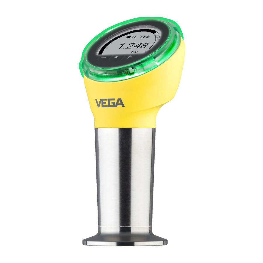
Scope of this operating This operating instructions manual applies to the following instrument instructions versions: • Hardware version from 1.0.0 • Software version from 1.1.0 VEGABAR 38 • Three-wire with IO-Link (2 x transistor or 4 … 20 mA plus 1 x transistor) - Page 8 Fig. 1: Components of VEGABAR 38 1 Process fitting Electronics housing Ventilation/pressure compensation Plug connector LED illuminated ring Display/adjustment unit Type label The type label contains the most important data for identification and use of the instrument. VEGABAR 38 • Three-wire with IO-Link (2 x transistor or 4 … 20 mA plus 1 x transistor)
-
Page 9: Principle Of Operation
Absolute pressure • Vacuum Measured products Measured products are gases, vapours and liquids. Depending on the process fitting and measurement setup, measured products can be also viscous or contain abrasive substances. VEGABAR 38 • Three-wire with IO-Link (2 x transistor or 4 … 20 mA plus 1 x transistor) - Page 10 The ambient pressure is detected in the measuring cell and compen- sated. It thus has no influence on the measured value. Absolute pressure: the measuring cell contains vacuum and is encapsulated. The ambient pressure is not compensated and does hence influence the measured value. VEGABAR 38 • Three-wire with IO-Link (2 x transistor or 4 … 20 mA plus 1 x transistor)
- Page 11 Lateral measuring cell seal Front measuring cell seal 4 Process fitting Diaphragm Front-flush installation in The front-flush, hygienic installation of the measuring cell is particu- hygienic fitting larly suitable for food applications. The front seal is installed gap-free. VEGABAR 38 • Three-wire with IO-Link (2 x transistor or 4 … 20 mA plus 1 x transistor)
-
Page 12: Adjustment
Smartphone/tablet (iOS or Android operating system) • PC/notebook (Windows operating system) Fig. 8: Wireless connection to standard operating devices with integrated Bluetooth LE Sensor Smartphone/Tablet PC/Notebook VEGABAR 38 • Three-wire with IO-Link (2 x transistor or 4 … 20 mA plus 1 x transistor) -
Page 13: Packaging, Transport And Storage
Threaded adapters enable simple adaptation of sensors with stand- ard threaded fittings, e.g. to process-side hygiene connections. Mounting accessories The suitable mounting accessories for VEGABAR 38 includes si- phons, blocking valves and measuring instrument holders. VEGABAR 38 • Three-wire with IO-Link (2 x transistor or 4 … 20 mA plus 1 x transistor) -
Page 14: Mounting
Tighten the cable gland or plug connector • When mounting horizontally, rotate the housing so that the cable gland or plug connector point downward VEGABAR 38 • Three-wire with IO-Link (2 x transistor or 4 … 20 mA plus 1 x transistor) - Page 15 Make sure that the upper temperature limits stated in chapter "Technical data" for the environment of the electronics hous- ing and connection cable are not exceeded. VEGABAR 38 • Three-wire with IO-Link (2 x transistor or 4 … 20 mA plus 1 x transistor)
-
Page 16: Process Pressure Measurement
VEGABAR 38 Blocking valve Pipeline In vapours Keep the following in mind when setting up the measuring system: • Connect via a siphon VEGABAR 38 • Three-wire with IO-Link (2 x transistor or 4 … 20 mA plus 1 x transistor) - Page 17 Fig. 13: Measurement setup for process pressure measurement of liquids in pipelines VEGABAR 38 Blocking valve Pipeline VEGABAR 38 • Three-wire with IO-Link (2 x transistor or 4 … 20 mA plus 1 x transistor)
-
Page 18: Level Measurement
• Mount the instrument so that it is protected against pressure shocks from the stirrer Fig. 14: Measurement setup for level measurement VEGABAR 38 • Three-wire with IO-Link (2 x transistor or 4 … 20 mA plus 1 x transistor) -
Page 19: Connecting To Power Supply
Connection procedure M12 x 1 plug This plug connection requires a complete confectioned cable with counter plug. VEGABAR 38 • Three-wire with IO-Link (2 x transistor or 4 … 20 mA plus 1 x transistor) -
Page 20: Wiring Plan
The output signal jumps to the set fault current • Switching outputs are controlled The current measured value is then output on the signal cable. With current output activated VEGABAR 38 • Three-wire with IO-Link (2 x transistor or 4 … 20 mA plus 1 x transistor) -
Page 21: Access Protection
"PINs and Codes". This greatly simplifies the setup of additional operating devices, as all device codes are au- tomatically synchronized when connected to the "myVEGA" account. VEGABAR 38 • Three-wire with IO-Link (2 x transistor or 4 … 20 mA plus 1 x transistor) - Page 22 VEGA contact person after legitimation. The storage and transmission of the device codes is always encrypted (SHA 256 algorithm). VEGABAR 38 • Three-wire with IO-Link (2 x transistor or 4 … 20 mA plus 1 x transistor)
-
Page 23: Set Up With The Integrated Display And Adjustment Unit
Navigation in the menu items, backwards Change parameter values downwards [+] and [-] Jump to next higher menu simultane- Interrupt input ously VEGABAR 38 • Three-wire with IO-Link (2 x transistor or 4 … 20 mA plus 1 x transistor) -
Page 24: Measured Value And Menu Item Display
The menu items are displayed according to the following diagram: 0.3000 bar Schaltpunkt Ausgang 1 Fig. 18: Display menu item (example) 1 Menu item code acc. to VDMA 24574-1 Actual parameter value Menu item name VEGABAR 38 • Three-wire with IO-Link (2 x transistor or 4 … 20 mA plus 1 x transistor) -
Page 25: Menu Overview
Indication of the switching status 100 % Pressure unit mbar Unit temperature °C Menu language English % values outputs referring to nominal measuring range VEGABAR 38 • Three-wire with IO-Link (2 x transistor or 4 … 20 mA plus 1 x transistor) -
Page 26: Parameter Adjustment
(SP). If the measured variable falls below the reset point (RP), the output returns to its previous state. VEGABAR 38 • Three-wire with IO-Link (2 x transistor or 4 … 20 mA plus 1 x transistor) - Page 27 Fig. 20: Window function If the measured variable moves within the window, the state of the output does not change. VEGABAR 38 • Three-wire with IO-Link (2 x transistor or 4 … 20 mA plus 1 x transistor)
- Page 28 Menu item code: • Parameter: • Pressure value Span The menu item Span (final value) defines the pressure value at the output current 20 mA. Menu item code: • Parameter: • Pressure value VEGABAR 38 • Three-wire with IO-Link (2 x transistor or 4 … 20 mA plus 1 x transistor)
- Page 29 20 % of the nominal measuring range, then no position correction is possible. Menu item code: • Parameter: • Pressure value VEGABAR 38 • Three-wire with IO-Link (2 x transistor or 4 … 20 mA plus 1 x transistor)
- Page 30 Only with M12 x 1 plug Only with OU2 VEGABAR 38 • Three-wire with IO-Link (2 x transistor or 4 … 20 mA plus 1 x transistor)
- Page 31 (FH) for the duration of the reset delay time, the output switches back to its previous state. DS DR DS DR Fig. 22: Effect of the delay time on the output with window function Menu item code: • • VEGABAR 38 • Three-wire with IO-Link (2 x transistor or 4 … 20 mA plus 1 x transistor)
- Page 32 • Indication of the switch- In this menu item you define the brightness of the LED illuminated ing status ring for the switching status display. LRV: Lower Range Value, URV: Upper Range Value VEGABAR 38 • Three-wire with IO-Link (2 x transistor or 4 … 20 mA plus 1 x transistor)
- Page 33 "PINs and Codes". If this is changed by the user and is no longer available, access is only pos- VEGABAR 38 • Three-wire with IO-Link (2 x transistor or 4 … 20 mA plus 1 x transistor)
- Page 34 During a reset, parameter settings made by the user are reset to the values of the basic setting or the delivery status (see chapter "Menu overview") Language and Bluetooth access code are not reset. VEGABAR 38 • Three-wire with IO-Link (2 x transistor or 4 … 20 mA plus 1 x transistor)
- Page 35 This menu item displays the number of parameter changes made. counter Menu item code: • Parameter delivery status only available with a parameter adjustment that deviates from the basic settings, e.g. customer-specific adjustment VEGABAR 38 • Three-wire with IO-Link (2 x transistor or 4 … 20 mA plus 1 x transistor)
- Page 36 Make sure the connected downstream devices are activated during the simulation. Menu item code: • Parameter: • Numerical value for pressure or current • Open or closed for switching output VEGABAR 38 • Three-wire with IO-Link (2 x transistor or 4 … 20 mA plus 1 x transistor)
- Page 37 7 Set up with the integrated display and adjustment unit Note: Without manual deactivation, the sensor terminates the simulation automatically after 60 minutes. VEGABAR 38 • Three-wire with IO-Link (2 x transistor or 4 … 20 mA plus 1 x transistor)
-
Page 38: Setup With Smartphone/Tablet (Bluetooth)
If an incorrect code is entered, the code can only be entered again after a delay time. This time gets longer after each incorrect entry. VEGABAR 38 • Three-wire with IO-Link (2 x transistor or 4 … 20 mA plus 1 x transistor) -
Page 39: Sensor Parameter Adjustment
On the left you'll find the navigation section with the menus "Setup", "Display", "Diagnosis" and others. The selected menu item, recognisable by the colour change, is dis- played in the right half. Fig. 24: Example of an app view - Setup sensor adjustment VEGABAR 38 • Three-wire with IO-Link (2 x transistor or 4 … 20 mA plus 1 x transistor) -
Page 40: Setup With Pc/Notebook (Bluetooth)
For authentication, enter in the next menu window the 6-digit code Bluetooth access code: Fig. 25: Enter Bluetooth access code You can find the code on the outside of the device housing and on the information sheet "PINs and Codes" in the device packaging. VEGABAR 38 • Three-wire with IO-Link (2 x transistor or 4 … 20 mA plus 1 x transistor) -
Page 41: Parameter Adjustment
DTMs are compiled in a DTM Collec- tion. The DTMs can also be integrated into other frame applications according to FDT standard. Fig. 26: Example of a DTM view - Adjustment current output VEGABAR 38 • Three-wire with IO-Link (2 x transistor or 4 … 20 mA plus 1 x transistor) -
Page 42: Diagnostics And Servicing
VEGA service hotline under the phone no. +49 1805 858550. The hotline is also available outside normal working hours, seven days a week around the clock. VEGABAR 38 • Three-wire with IO-Link (2 x transistor or 4 … 20 mA plus 1 x transistor) -
Page 43: Diagnosis, Fault Messages
Status messages The status messages are divided into the following categories: • Failure • Function check Adjustable via VEGA Tools app or PACTware/DTM VEGABAR 38 • Three-wire with IO-Link (2 x transistor or 4 … 20 mA plus 1 x transistor) - Page 44 General software error F110 Selected switching points too close to- Increase the distance between the gether switching points Switching points too close to- gether VEGABAR 38 • Three-wire with IO-Link (2 x transistor or 4 … 20 mA plus 1 x transistor)
-
Page 45: Software Update
• PC/notebook with PACTware/DTM and Bluetooth USB adapter • Current instrument software as file You can find the current instrument software as well as detailed infor- mation on the procedure in the download area of our homepage. VEGABAR 38 • Three-wire with IO-Link (2 x transistor or 4 … 20 mA plus 1 x transistor) -
Page 46: How To Proceed If A Repair Is Necessary
Attach the completed form and, if need be, also a safety data sheet outside on the packaging • Ask the agency serving you to get the address for the return ship- ment. You can find the agency on our homepage. VEGABAR 38 • Three-wire with IO-Link (2 x transistor or 4 … 20 mA plus 1 x transistor) -
Page 47: Dismount
The device is made of recyclable materials. For this reason, it should be disposed of by a specialist recycling company. Observe the ap- plicable national regulations. VEGABAR 38 • Three-wire with IO-Link (2 x transistor or 4 … 20 mA plus 1 x transistor) -
Page 48: Certificates And Approvals
DIN EN ISO 14001. Please help us fulfil this obligation by observing the environmental instructions in this manual: • Chapter "Packaging, transport and storage" • Chapter "Disposal" VEGABAR 38 • Three-wire with IO-Link (2 x transistor or 4 … 20 mA plus 1 x transistor) -
Page 49: Supplement
Ʋ Thread G½ (EN 837), G1 (ISO 228-1), 50 Nm (36.88 lbf ft) G1½ (DIN 3852-A) Ʋ Thread G1 with conus 100 Nm (73.76 lbf ft) VEGABAR 38 • Three-wire with IO-Link (2 x transistor or 4 … 20 mA plus 1 x transistor) - Page 50 0 … +75 psig +950 psig -14.51 psig 0 … +150 psig +1300 psig -14.51 psig Data on overload capability apply for reference temperature. VEGABAR 38 • Three-wire with IO-Link (2 x transistor or 4 … 20 mA plus 1 x transistor)
- Page 51 Damping (63 % of the input variable), 0 … 999 s adjustable Output variable - Three-wire 1 x transistor Output signal Transistor PNP or NPN can be configured Connection technology Three-wire VEGABAR 38 • Three-wire with IO-Link (2 x transistor or 4 … 20 mA plus 1 x transistor)
- Page 52 Fig. 28: Behaviour the current output in case of sudden change of the process variable. t : dead time; t : rise time; : jump response time Process variable Output signal Size Time Dead time ≤ 4 ms VEGABAR 38 • Three-wire with IO-Link (2 x transistor or 4 … 20 mA plus 1 x transistor)
- Page 53 Fig. 29: Temperature error with TD 1 : 1 In the compensated temperature range 0 … +100 °C (+32 … +212 °F). VEGABAR 38 • Three-wire with IO-Link (2 x transistor or 4 … 20 mA plus 1 x transistor)
- Page 54 Process temperature Ambient temperature Relative humidity 20 … 85 % Process pressures > 5 bar: 20 … +60 °C (-4 … +140 °F) VEGABAR 38 • Three-wire with IO-Link (2 x transistor or 4 … 20 mA plus 1 x transistor)
- Page 55 4-pole with M12 x 1 screw connection Voltage supply Operating voltage U 12 … 35 V DC MWP: Maximum Working Pressure Depending on the local conditions VEGABAR 38 • Three-wire with IO-Link (2 x transistor or 4 … 20 mA plus 1 x transistor)
-
Page 56: Io-Link
Speed: COM2 38.4 kBaud Min. cycle time 4.0 ms Length process data word: 32 Bit IO-Link Data Storage: Yes Block parameter adjustment: Yes VEGABAR 38 • Three-wire with IO-Link (2 x transistor or 4 … 20 mA plus 1 x transistor) - Page 57 (read). The ISDU (Indexed Service Data Unit) determines, among other things, whether the data is read or written. VEGABAR 38 • Three-wire with IO-Link (2 x transistor or 4 … 20 mA plus 1 x transistor)
- Page 58 Float Reset point (RP1) 0x0103 Float Switching delay (DS1) 0x0104 Float 0.0 … 60.0 Reset delay (DR1) 0x0105 Float 0.0 … 60.0 VEGABAR 38 • Three-wire with IO-Link (2 x transistor or 4 … 20 mA plus 1 x transistor)
- Page 59 1=Red, 2=Or- ange, 3=White, 4=Green, 5=Blue, 6=Yellow, 7=No signalling Switching output 0x011E Unsigned8 Operating Status 0x011F Unsigned8 Lighting (DIS) 0x0120 Unsigned8 0=Off, 1=On VEGABAR 38 • Three-wire with IO-Link (2 x transistor or 4 … 20 mA plus 1 x transistor)
- Page 60 Max. measuring cell tem- 0x0136 Float perature Electronics temperature 0x0137 Float Min. electronics temper- 0x0138 Float ature Max. electronics temper- 0x0139 Float ature VEGABAR 38 • Three-wire with IO-Link (2 x transistor or 4 … 20 mA plus 1 x transistor)
- Page 61 Reset pointer function, temperature 0x0A1 Reset pointer function, electronic temperture 0x0A2 Accept 4 mA (LRV) 0x0A3 Accept 20 mA (URV) 0x0A4 Accept setpoint value 0x0A5 VEGABAR 38 • Three-wire with IO-Link (2 x transistor or 4 … 20 mA plus 1 x transistor)
-
Page 62: Dimensions
13 Supplement 13.3 Dimensions Connection technology 35 mm 40 mm (1.38") (1.57") Fig. 32: Connection technology VEGABAR 38 VEGABAR 38 • Three-wire with IO-Link (2 x transistor or 4 … 20 mA plus 1 x transistor) - Page 63 C2 Thread M20 x 1.5 (EN 837), manometer connection LF Thread ½ NPT, inside ¼ NPT (ASME B1.20.1) Thread ¼ NPT (ASME B1.20.1) CS Thread G½, inside G¼ (ISO 228-1), Duplex (1.4462) DQ Thread G½, inside G¼ (ISO 228-1), PVDF VEGABAR 38 • Three-wire with IO-Link (2 x transistor or 4 … 20 mA plus 1 x transistor)
- Page 64 ( 2.17 ") Fig. 34: VEGABAR 38, threaded fitting front-flush C3 Thread G½ (ISO 228-1) N9 Thread G¾ (DIN 3852-E) C5 Thread G1 (ISO 228-1) DS Thread 1 NPT (ASME B1.20.1) DA Thread G1½ (DIN 3852-A) C9 Thread 1½ NPT (ASME B1.20.1) VEGABAR 38 • Three-wire with IO-Link (2 x transistor or 4 … 20 mA plus 1 x transistor)
- Page 65 ø 40 mm ( 1.08 ") ( 1.57 ") ( 1.57 ") Fig. 35: VEGABAR 38, cone/extension fitting DH Thread G1 (ISO 228-1), cone 40° LX Thread G1 (ISO 228-1), hygienic design AL Thread M30 x 1.5 (DIN 13) VEGABAR 38 • Three-wire with IO-Link (2 x transistor or 4 … 20 mA plus 1 x transistor)
- Page 66 FB SMS DN51 PN6 E7 Ingold connection PN 10 FR Varivent N50-40 PN 25 EZ Collar socket DN 40 PN 40 (DIN 11851) E2 Collar socket DN 40 PN 40 (DIN 11864-1, Form A) VEGABAR 38 • Three-wire with IO-Link (2 x transistor or 4 … 20 mA plus 1 x transistor)
-
Page 67: Industrial Property Rights
License. 13.6 Trademark All the brands as well as trade and company names used are property of their lawful proprietor/ originator. VEGABAR 38 • Three-wire with IO-Link (2 x transistor or 4 … 20 mA plus 1 x transistor) - Page 68 Subject to change without prior notice © VEGA Grieshaber KG, Schiltach/Germany 2019 VEGA Grieshaber KG Phone +49 7836 50-0 Am Hohenstein 113...
Need help?
Do you have a question about the VEGABAR 38 and is the answer not in the manual?
Questions and answers