Table of Contents
Advertisement
Quick Links
—
A B B M EA S U R E M E N T & A N A L Y T I C S | O P E R A T I N G I N S T R U C T I O N | O I / E L 3 0 0 0 - E N R E V . D
EasyLine EL3000
Continuous gas analyzers
—
Introduction
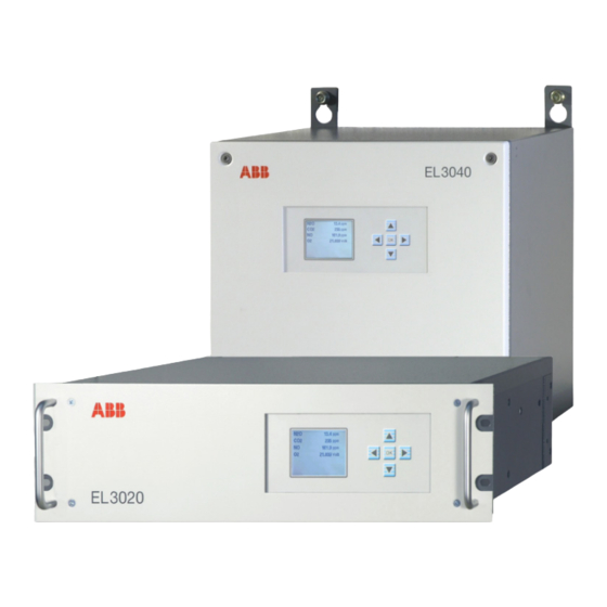
EasyLine EL3020
EasyLine EL3040
EasyLine is a powerful yet cost-effective line of
devices for the measurement of gas
concentrations in numerous applications.
Automatic calibration and the use of superior ABB
calibration cell technology in the photometer
avoids the use of expensive test gas cylinders in
most applications.
Zero-point calibration with ambient air
Various analyzer types available:
Combining different analyzers in a single housing
enables optimum economy and operational
efficiency for your application.
So smart, they're simple
Measurement made easy
Additional Information
Additional documentation on EasyLine EL3000 is
available for download free of charge at
www.abb.com/analytical.
Alternatively simply scan this code:
Advertisement
Table of Contents
Troubleshooting

Related Manuals for ABB EasyLine EL3000


Summary of Contents for ABB EasyLine EL3000
- Page 1 Alternatively simply scan this code: Automatic calibration and the use of superior ABB calibration cell technology in the photometer avoids the use of expensive test gas cylinders in most applications.
-
Page 2: Table Of Contents
EL3000 CONTINUOUS GAS ANALYZERS | OI/EL3000-EN REV. D Table of contents Electrical connections ..........93 Safety ................ 4 Safety instructions .............. 93 General information and instructions ......... 4 General Notes ............... 93 Warnings .................. 4 Model EL3020 ............... 93 Warranty provisions ............... 4 Model EL3040 ............... - Page 3 EL3000 CONTINUOUS GAS ANALYZERS | OI/EL3000-EN REV. D 10 Configuration ............141 13 Maintenance ............177 Measuring range switchover..........141 Safety instructions ............. 177 Measuring range configuration with ECT ....... 142 Inspection ................177 Measuring range configuration in the gas analyzer ..144 Maintenance switch ............178 Uras26 –...
-
Page 4: Safety
EL3000 CONTINUOUS GAS ANALYZERS | OI/EL3000-EN REV. D 1 Safety Warnings General information and instructions The warnings in these instructions are structured as follows: These instructions are an important part of the product and must be retained for future reference. DANGER Installation, commissioning, and maintenance of the product may only be performed by trained specialist personnel who have... -
Page 5: Intended Use
EL3000 CONTINUOUS GAS ANALYZERS | OI/EL3000-EN REV. D Intended use Operation in hazardous areas The gas analyzer is designed for continuous measurement of the DANGER concentration of individual components in gases or vapors. Explosion hazard Any other use is not approved. Explosion hazard when measuring flammable gases in The intended use also includes taking note of this operating hazardous areas. -
Page 6: Safety Instructions
EL3000 CONTINUOUS GAS ANALYZERS | OI/EL3000-EN REV. D … 1 Safety Safety instructions Requirements for safe operation Potential equalization In order to operate in a safe and efficient manner the device • The external potential equalization connection of the should be properly handled and stored, correctly installed and analyzer housing must be connected to the local potential set-up, properly operated and correctly maintained. -
Page 7: Fidas24 - Information For Safe Operation
EL3000 CONTINUOUS GAS ANALYZERS | OI/EL3000-EN REV. D Fidas24 – Information for safe operation Conditions to be complied with by the end user DANGER The end user must comply with the following prerequisites and Explosion hazard conditions to ensure safe operation of the gas analyzer: Explosion hazard due to leaking combustion gas (hydrogen). -
Page 8: Notes On Data Safety
/ or theft of data or information. the gas analyzer. ABB Ltd and its affiliates are not liable for damages and / or This shut-off valve should be installed outside the losses related to such security breaches, any unauthorized... -
Page 9: Manufacturer's Address
Tel: +49 69 7930-4666 Email: cga@de.abb.com Service address If the information in this Operating Instruction does not cover a particular situation, ABB Service will be pleased to supply additional information as required. Please contact your local service representative. For emergencies, please contact:... -
Page 10: Use In Potentially Explosive Atmospheres
Repairs by the manufacturer installations must be disconnected from the power supply. Repairs can also be carried out by the manufacturer, for example on-site by an ABB Service employee or at the manufacturing The disconnect point must be identified with an appropriate plant. -
Page 11: Explosion Proof Design In Degree Of Protection Ii 3G
II 3G Ex ec nC IIC T4 Gc Note All documentation, declarations of conformity, and certificates In undisturbed operation there cannot be any sparking, arcing or are available in ABB's download area. impermissible temperatures inside the device. www.abb.com/analytical Explosion protection through: increased safety as well as gasketed or encapsulated equipment. - Page 12 EL3000 CONTINUOUS GAS ANALYZERS | OI/EL3000-EN REV. D … 2 Use in potentially explosive atmospheres … Explosion proof design in degree of protection II 3G Characteristic values Special conditions • The cables must be inserted into the cable glands properly and gasketed by tightening the screws so that the IP 65 System bus, computer housing protection is maintained.
-
Page 13: Design And Function
1 LCD indicator 2 Gas and electrical connections Figure 1: EasyLine EL3000 housing designs The EL3020 gas analyzer model features a 19” housing with 3 HU (4 HU with Magnos27) and IP rating IP 20 (IP 40 in the version for emissions monitoring). -
Page 14: Available Analyzer Modules
EL3000 CONTINUOUS GAS ANALYZERS | OI/EL3000-EN REV. D … 3 Design and function Available analyzer combinations Available analyzer modules The following analyzer modules are available for selection: Analyzer combination EL3020 EL3040 • Uras26 infrared photometer • • Uras26 with Magnos206 for the measurement of infrared-active gas components, •... -
Page 15: Preparation For Installation
EL3000 CONTINUOUS GAS ANALYZERS | OI/EL3000-EN REV. D 4 Preparation for Installation Scope of delivery Material required for installation Note • Gas analyzer model EL3020 (19” housing) or model EL3040 The materials listed below are not included in the scope of (wall housing) delivery of the device, and must be provided by the customer. - Page 16 EL3000 CONTINUOUS GAS ANALYZERS | OI/EL3000-EN REV. D … 4 Preparation for Installation … Material required for installation Shut-off valve Signal Lines Install a shut-off valve in the sample gas line (recommended Select conductive material which is appropriate for the length of when the sample gas is pressurized).
-
Page 17: Requirements For The Installation Site
EL3000 CONTINUOUS GAS ANALYZERS | OI/EL3000-EN REV. D Requirements for the installation site Note Climatic Conditions For the analyzers ZO23 and Fidas24, the instructions specified in Relative humidity ZO23 on page 28 or Fidas24 on page 33 must be observed. Maximum 75 %, no condensation Installation site requirements Ambient temperature... -
Page 18: Power Supply
EL3000 CONTINUOUS GAS ANALYZERS | OI/EL3000-EN REV. D … 4 Preparation for Installation Power supply … Requirements for the installation site Electric information (entire device) Special conditions for the model EL3040 gas analyzer in The power supply built into the system housing is used to supply degree of protection II 3G 24 V DC to the analyzer module and the associated electronics. -
Page 19: Uras26
EL3000 CONTINUOUS GAS ANALYZERS | OI/EL3000-EN REV. D Uras26 Sample gas Flowing reference gas Sample gas inlet conditions Gas inlet conditions as for sample gas DANGER Pressure sensor Explosion hazard The pressure sensor is installed in the gas analyzer as standard, Explosion hazard when measuring ignitable gas / air or see Pressure sensor on page 36. - Page 20 EL3000 CONTINUOUS GAS ANALYZERS | OI/EL3000-EN REV. D … 4 Preparation for Installation … Uras26 Test gases – Uras26 Analyzer(s) Test gas for the zero calibration Test gas for the end-point calibration Uras26 with calibration cells or air or sample component-free gas —...
-
Page 21: Limas23
EL3000 CONTINUOUS GAS ANALYZERS | OI/EL3000-EN REV. D Limas23 Sample gas Pressure sensor Sample gas inlet conditions The pressure sensor is installed in the gas analyzer as standard, see Pressure sensor on page 36. DANGER Explosion hazard The pressure sensor is connected to the sample gas path or a Explosion hazard when measuring flammable gases and connection socket at different positions depending on the ignitable gas / air or gas / oxygen mixtures... - Page 22 EL3000 CONTINUOUS GAS ANALYZERS | OI/EL3000-EN REV. D … 4 Preparation for Installation … Limas23 Test gases – Limas23 Analyzer(s) Test gas for the zero calibration Test gas for the end-point calibration Limas23 with calibration cells or air or UV sample component-free gas Calibration cells or test gas for each sample (automatic calibration) component...
-
Page 23: Magnos206
EL3000 CONTINUOUS GAS ANALYZERS | OI/EL3000-EN REV. D Magnos206 Sample gas Sample gas inlet conditions Corrosive gases If the sample gas contains Cl , HCl, HF or other corrosive DANGER components, the analyzer may only be used if the sample gas Explosion hazard composition has been taken into account by the manufacturer Explosion hazard when measuring ignitable gas / air or... - Page 24 EL3000 CONTINUOUS GAS ANALYZERS | OI/EL3000-EN REV. D … 4 Preparation for Installation … Magnos206 Test gases – Magnos206 Analyzer Test gas for zero point calibration and single-point Test gas for the end-point calibration calibration Magnos206 Oxygen-free process gas Process gas with a known O concentration Magnos206 suppressed measuring range •...
-
Page 25: Magnos28
EL3000 CONTINUOUS GAS ANALYZERS | OI/EL3000-EN REV. D Magnos28 Sample gas Sample gas inlet conditions Corrosive gases If the sample gas contains Cl , HCl, HF or other corrosive DANGER components, the analyzer may only be used if the sample gas Explosion hazard composition has been taken into account by the manufacturer Explosion hazard when measuring ignitable gas / air or... - Page 26 EL3000 CONTINUOUS GAS ANALYZERS | OI/EL3000-EN REV. D … 4 Preparation for Installation … Magnos28 Test gases – Magnos28 Analyzer Test gas for zero point calibration and single-point Test gas for the end-point calibration calibration Magnos28 Oxygen-free process gas Process gas with a known O concentration Magnos28 with a suppressed measuring •...
-
Page 27: Magnos27
EL3000 CONTINUOUS GAS ANALYZERS | OI/EL3000-EN REV. D Magnos27 Sample gas Tests gases – Magnos27 Sample gas inlet conditions DANGER Analyzer Test gas for the zero Test gas for the end-point calibration calibration Explosion hazard Magnos27 Oxygen-free process gas Process gas with a known Explosion hazard when measuring flammable gases and concentration ignitable gas / air or gas / oxygen mixtures... -
Page 28: Zo23
EL3000 CONTINUOUS GAS ANALYZERS | OI/EL3000-EN REV. D … 4 Preparation for Installation ZO23 Sample gas Sample gas inlet conditions Associated gas effect DANGER Inert gases (Ar, N ) have no effect. Flammable gases (CO, H ) in stoichiometric concentrations to the oxygen content: Explosion hazard conversion O <... - Page 29 EL3000 CONTINUOUS GAS ANALYZERS | OI/EL3000-EN REV. D Installation and sample handling NOTICE Damage to the measuring cell The ingress of liquids into the analyzer module can cause serious damage including destruction of the sample cell. Note The following information on installation and the sample handling must be considered for the measurement and the execution of controlled calibrations (manual, automatic and externally controlled calibration).
- Page 30 EL3000 CONTINUOUS GAS ANALYZERS | OI/EL3000-EN REV. D … 4 Preparation for Installation … ZO23 Gas sampling Bypass The nominal diameter of the line from the sampling point to the The gas analyzer is connected to a gas flow in the bypass at a first switch-over valve should be 4 mm.
-
Page 31: Caldos27
EL3000 CONTINUOUS GAS ANALYZERS | OI/EL3000-EN REV. D Caldos27 Sample gas Pressure sensor Sample gas inlet conditions The pressure sensor is installed in the gas analyzer at the factory, see Pressure sensor on page 36. DANGER The pressure sensor is connected to a connection socket via an Explosion hazard FPM tube. - Page 32 EL3000 CONTINUOUS GAS ANALYZERS | OI/EL3000-EN REV. D … 4 Preparation for Installation … Caldos27 Test gases – Caldos27 Analyzer Test gas for zero point calibration and single-point Test gas for the end-point calibration calibration Caldos27 Sample component-free test gas or process gas Test gas or process gas with a known sample component concentration Caldos27 with a suppressed...
-
Page 33: Fidas24
EL3000 CONTINUOUS GAS ANALYZERS | OI/EL3000-EN REV. D Fidas24 Sample gas Operational gases Sample components Instrument air Hydrocarbons. The concentration of the gas components in the sample gas path must not exceed the temperature-dependent Parameter Value/Description LEL. The analyzer temperature is 180 °C. Quality According to ISO 8573-1 Class 2 Particle size: max. - Page 34 (cylinder, line). Combustion gas parameter Quality Hydrogen (H /He mix ABB recommends the use of a pneumatic shut-off valve that is Quality 5.0 (40 %/60 %) actuated by the instrument air. This shut-off valve can be Inlet pressure p 1200 hPa, ±100 hPa...
-
Page 35: Sample Gas Input And Output Conditions
EL3000 CONTINUOUS GAS ANALYZERS | OI/EL3000-EN REV. D Sample gas input and output conditions Analyzers Test gases Analyzer Additional Information Test Gases for Zero Calibration Quality Nitrogen, Quality 5.0, synthetic air or catalytically Uras26 See page 19 cleaned air with an organic C < 1 % MBU Limas23 See page 21 Inlet pressure p... -
Page 36: Pressure Sensor
EL3000 CONTINUOUS GAS ANALYZERS | OI/EL3000-EN REV. D … 4 Preparation for Installation … Sample gas input and output conditions Pressure sensor In which analyzer modules is a pressure sensor installed? Special conditions for the model EL3040 gas analyzer in degree of protection II 3G Flammable gases Gas analyzer... -
Page 37: Housing Purge
EL3000 CONTINUOUS GAS ANALYZERS | OI/EL3000-EN REV. D Housing purge Housing design Initial purging upon commissioning Housing purging is only possible with the wall-mounted housing (model EL3040). The purge gas connectors (⅛ NPT female Housing purge* thread) are factory-installed in accordance with the order. Purge gas Nitrogen Purge gas flow... -
Page 38: Dimensions
EL3000 CONTINUOUS GAS ANALYZERS | OI/EL3000-EN REV. D … 4 Preparation for Installation Dimensions 19” housing (model EL3020) Dimensions in mm (in) Figure 3: 19” housing (model EL3020) - Page 39 EL3000 CONTINUOUS GAS ANALYZERS | OI/EL3000-EN REV. D 19” housing (model EL3020 with Magnos27) Dimensions in mm (in) Figure 4: 19″housing (model EL3020 with Magnos27) Note Only the front view of the housing (with its height differing from the standard dimension) is depicted in this dimensional drawing. Additional views and dimensions of the 19”...
- Page 40 EL3000 CONTINUOUS GAS ANALYZERS | OI/EL3000-EN REV. D … 4 Preparation for Installation … Dimensions Wall-mount housing (model EL3040) Dimensions in mm (in) A Consider free space to swivel the door Figure 5: Wall-mount housing (model EL3040)
-
Page 41: Special Conditions For The Measurement Of Combustion Gases
EL3000 CONTINUOUS GAS ANALYZERS | OI/EL3000-EN REV. D Special conditions for the measurement of combustion gases Installation of the gas analyzer DANGER • The pressure sensor must not be connected to the sample Explosion hazard gas path. Explosion hazard due to the formation of explosive gas •... - Page 42 EL3000 CONTINUOUS GAS ANALYZERS | OI/EL3000-EN REV. D … 4 Preparation for Installation … Special conditions for the measurement of combustion gases Commissioning of the gas analyzer • The sample gas path must be purged with inert gas before the gas analyzer is commissioned (see Purge sample gas path and analyzer housing on page 103).
-
Page 43: Installation
EL3000 CONTINUOUS GAS ANALYZERS | OI/EL3000-EN REV. D 5 Installation Unpacking the Gas Analyzer Analyzer data sheet CAUTION Contents The analyzer data sheet contains the following information: Injury hazard due to heavy weight • Order Number (O-No.), Depending on the version, the gas analyzer weighs7 to 15 kg •... -
Page 44: Mounting The Fittings On The Gas Analyzer
EL3000 CONTINUOUS GAS ANALYZERS | OI/EL3000-EN REV. D … 5 Installation Mounting the fittings on the gas analyzer General information Requisite Material To connect the gas lines to the gas analyzer, screw-in sockets Screw-in spud with hose nozzles (supplied) or screw-in fittings (fittings) are used in different designs. -
Page 45: Position And Design Of The Gas Connections
EL3000 CONTINUOUS GAS ANALYZERS | OI/EL3000-EN REV. D Position and design of the gas connections The following pages list the location and execution of the gas connections of the individual analyzer modules and their combinations. The table below is used as an aid in navigating the connection descriptions. Position and design of the gas connections Analyzer module Model EL3020... - Page 46 EL3000 CONTINUOUS GAS ANALYZERS | OI/EL3000-EN REV. D … 5 Installation … Position and design of the gas connections Gas connections Uras26 (model EL3020) Figure 6: Gas connections Uras26 (EL3020) Uras26: Gas connections for hose lines (internal gas lines made using hoses) Pos.
- Page 47 EL3000 CONTINUOUS GAS ANALYZERS | OI/EL3000-EN REV. D Uras26: Gas connections for pipelines (internal gas lines made stainless steel pipes) Pos. Connection Supplementary information Version Pressure sensor — Screwed connections with hose nozzles (stainless steel 1.4305) for hoses with 4 mm inside diameter (included in scope of supply) Sample gas inlet —...
- Page 48 EL3000 CONTINUOUS GAS ANALYZERS | OI/EL3000-EN REV. D … 5 Installation … Position and design of the gas connections Gas connections Uras26 (model EL3040) Figure 7: Gas connections Uras26 (model EL3040) Uras26: Gas connections Pos. Connection Supplementary information Version Pressure sensor The pressure sensor is connected to the Pos.
- Page 49 EL3000 CONTINUOUS GAS ANALYZERS | OI/EL3000-EN REV. D Gas connections Uras26 with Magnos206 (model EL3020) Figure 8: Gas connections Uras26 with Magnos206 (model EL3020) Uras26: Gas connections for hose lines (internal gas lines made using hoses) Pos. Connection Supplementary information Version Sample gas inlet (gas path 1) Without ‘integrated gas feed’...
- Page 50 EL3000 CONTINUOUS GAS ANALYZERS | OI/EL3000-EN REV. D … 5 Installation … Position and design of the gas connections Uras26: Gas connections for pipelines (internal gas lines made stainless steel pipes) Pos. Connection Supplementary information Version Pressure sensor — Screwed connections with hose nozzles (stainless steel 1.4305) for hoses with 4 mm inside diameter (included in scope of supply) Sample gas inlet...
- Page 51 EL3000 CONTINUOUS GAS ANALYZERS | OI/EL3000-EN REV. D Gas connections Uras26 with Magnos206 (model EL3040) Figure 9: Gas connections Uras26 with Magnos206 (model EL3040) Uras26: Gas connections Pos. Connection Supplementary information Version Pressure sensor The pressure sensor is connected to the Pos. 1 terminal if ⅛...
- Page 52 EL3000 CONTINUOUS GAS ANALYZERS | OI/EL3000-EN REV. D … 5 Installation … Position and design of the gas connections Magnos206: Gas Connections Pos. Connection Supplementary information Version Sample gas inlet — ⅛ NPT female thread (stainless steel 1.4305) • Connection of hose lines: Sample gas outlet —...
- Page 53 EL3000 CONTINUOUS GAS ANALYZERS | OI/EL3000-EN REV. D Gas connections Uras26 with Magnos28 (model EL3020) Figure 10: Gas connections Uras26 with Magnos28 (EL3020) Uras26: Gas connections for hose lines (internal gas lines made using hoses) Pos. Connection Supplementary information Version Sample gas inlet (gas path 1) Without ‘integrated gas feed’...
- Page 54 EL3000 CONTINUOUS GAS ANALYZERS | OI/EL3000-EN REV. D … 5 Installation … Position and design of the gas connections Uras26: Gas connections for pipelines (internal gas lines made stainless steel pipes) Pos. Connection Supplementary information Version Pressure sensor — Screwed connections with hose nozzles (stainless steel 1.4305) for hoses with 4 mm inside diameter (included in scope of supply) Sample gas inlet...
- Page 55 EL3000 CONTINUOUS GAS ANALYZERS | OI/EL3000-EN REV. D Gas connections Uras26 with Magnos28 (model EL3040) Figure 11: Gas connections Uras26 with Magnos28 (model EL3040) Uras26: Gas connections (internal gas lines made using hoses or stainless steel pipes) Pos. Connection Supplementary information Version Pressure sensor The pressure sensor is connected to the Pos.
- Page 56 EL3000 CONTINUOUS GAS ANALYZERS | OI/EL3000-EN REV. D … 5 Installation … Position and design of the gas connections Magnos28: Gas Connections Pos. Connection Supplementary information Version Sample gas inlet — ⅛ NPT female thread (stainless steel 1.4305) • Connection of hose lines: Sample gas outlet —...
- Page 57 EL3000 CONTINUOUS GAS ANALYZERS | OI/EL3000-EN REV. D Gas connections Uras26 with Caldos27 (model EL3020) Figure 12: Gas connections Uras26 with Caldos27 (model EL3020) Uras26: Gas connections for hose lines (internal gas lines made using hoses) Pos. Connection Supplementary information Version Sample gas inlet (gas path 1) Without ‘integrated gas feed’...
- Page 58 EL3000 CONTINUOUS GAS ANALYZERS | OI/EL3000-EN REV. D … 5 Installation … Position and design of the gas connections Uras26: Gas connections for pipelines (internal gas lines made stainless steel pipes) Pos. Connection Supplementary information Version Pressure sensor — Screwed connections with hose nozzles (stainless steel 1.4305) for hoses with 4 mm inside diameter (included in scope of supply) Sample gas inlet...
- Page 59 EL3000 CONTINUOUS GAS ANALYZERS | OI/EL3000-EN REV. D Gas connections Uras26 with Caldos27 (model EL3040) Figure 13: Gas connections Uras26 with Caldos27 (model EL3040) Uras26: Gas connections Pos. Connection Supplementary information Version Pressure sensor The pressure sensor is connected to the Pos. 1 terminal if ⅛...
- Page 60 EL3000 CONTINUOUS GAS ANALYZERS | OI/EL3000-EN REV. D … 5 Installation … Position and design of the gas connections Caldos27: Gas Connections Pos. Connection Supplementary information Version Sample gas inlet — ⅛ NPT female thread (stainless steel 1.4305) • Connection of hose lines: Sample gas outlet —...
- Page 61 EL3000 CONTINUOUS GAS ANALYZERS | OI/EL3000-EN REV. D Gas connections Limas23 (model EL3020) Figure 14: Gas connections Limas23 (model EL3020) Limas23: Gas connections Pos. Connection Supplementary information Version Sample gas inlet Without optional solenoid valve Screwed connections with hose nozzles (stainless steel 1.4305) for hoses with 4 mm inside diameter Sample gas outlet —...
- Page 62 EL3000 CONTINUOUS GAS ANALYZERS | OI/EL3000-EN REV. D … 5 Installation … Position and design of the gas connections Gas connections Limas23 (model EL3040) Figure 15: Gas connections Limas23 (model EL3040) Limas23: Gas connections Pos. Connection Supplementary information Version Sample gas inlet —...
- Page 63 EL3000 CONTINUOUS GAS ANALYZERS | OI/EL3000-EN REV. D Gas connections Limas23 with Magnos206 (model EL3020) Figure 16: Gas connections Limas23 with Magnos206 (model EL3020) Limas23: Gas connections Pos. Connection Supplementary information Version Sample gas inlet Without optional solenoid valve Screwed connections with hose nozzles (stainless steel 1.4305) for hoses with 4 mm inside diameter Sample gas outlet —...
- Page 64 EL3000 CONTINUOUS GAS ANALYZERS | OI/EL3000-EN REV. D … 5 Installation … Position and design of the gas connections Gas connections Limas23 with Magnos206 (model EL3040) Figure 17: Gas connections Limas23 with Magnos206 (model EL3040) Limas23: Gas connections Pos. Connection Supplementary information Version Sample gas inlet...
- Page 65 EL3000 CONTINUOUS GAS ANALYZERS | OI/EL3000-EN REV. D Magnos206: Gas Connections Pos. Connection Supplementary information Version Sample gas inlet — ⅛ NPT female thread (stainless steel 1.4305) • Connection of hose lines: Sample gas outlet — straight screw-in socket (PP) with hose nozzles Not assigned —...
- Page 66 EL3000 CONTINUOUS GAS ANALYZERS | OI/EL3000-EN REV. D … 5 Installation … Position and design of the gas connections Gas connections Limas23 with Magnos28 (model EL3020) Figure 18: Gas connections Limas23 with Magnos28 (model EL3020) Limas23: Gas connections Pos. Connection Supplementary information Version Sample gas inlet...
- Page 67 EL3000 CONTINUOUS GAS ANALYZERS | OI/EL3000-EN REV. D Gas connections Limas23 with Magnos28 (model EL3040) Figure 19: Gas connections Limas23 with Magnos28 (model EL3040) Limas23: Gas connections Pos. Connection Supplementary information Version Sample gas inlet — ⅛ NPT female thread (stainless steel 1.4305) •...
- Page 68 EL3000 CONTINUOUS GAS ANALYZERS | OI/EL3000-EN REV. D … 5 Installation … Position and design of the gas connections Magnos28: Gas Connections Pos. Connection Supplementary information Version Sample gas inlet — ⅛ NPT female thread (stainless steel 1.4305) • Connection of hose lines: Sample gas outlet —...
- Page 69 EL3000 CONTINUOUS GAS ANALYZERS | OI/EL3000-EN REV. D Gas connections Magnos206 (model EL3020) Figure 20: Gas connections Magnos206 (model EL3020) Magnos206: Gas Connections Pos. Connection Supplementary information Version Sample gas inlet — ⅛ NPT female thread (stainless steel 1.4305) • Connection of hose lines: straight screw-in socket (PP) with hose nozzles for Sample gas outlet...
- Page 70 EL3000 CONTINUOUS GAS ANALYZERS | OI/EL3000-EN REV. D … 5 Installation … Position and design of the gas connections Gas connections Magnos206 (model EL3040) Figure 21: Gas connections Magnos206 (model EL3040) Magnos206: Gas Connections Pos. Connection Supplementary information Version Sample gas inlet —...
- Page 71 EL3000 CONTINUOUS GAS ANALYZERS | OI/EL3000-EN REV. D Gas connections Magnos28 (model EL3020) Figure 22: Gas connections Magnos28 (model EL3020) Magnos28: Gas Connections Pos. Connection Supplementary information Version Sample gas inlet — ⅛ NPT female thread (stainless steel 1.4305) Sample gas outlet —...
- Page 72 EL3000 CONTINUOUS GAS ANALYZERS | OI/EL3000-EN REV. D … 5 Installation … Position and design of the gas connections Gas connections Magnos28 with Magnos28 (model EL3020) Figure 23: Gas connections Magnos28 with Magnos28 (model EL3020) Magnos28 – gas connections for direct connection (applies to both analyzer modules) Pos.
- Page 73 EL3000 CONTINUOUS GAS ANALYZERS | OI/EL3000-EN REV. D Gas connections Magnos28 with Caldos27 (model EL3020) Figure 24: Gas connections Magnos28 with Caldos27 (model EL3020) Magnos28 – gas connections for direct connection Pos. Connection Supplementary information Version Sample gas inlet — ⅛...
- Page 74 EL3000 CONTINUOUS GAS ANALYZERS | OI/EL3000-EN REV. D … 5 Installation … Position and design of the gas connections Magnos28 with Caldos27 – gas connections for ‘Integral gas feed’ option with flow sensor Pos. Connection Supplementary information Version Sample gas outlet Factory-connected to Magnos28 sample gas inlet 1 Screwed connections with hose nozzles (stainless (gas path 1 / Magnos28)
- Page 75 EL3000 CONTINUOUS GAS ANALYZERS | OI/EL3000-EN REV. D Gas connections Magnos28 (model EL3040) Figure 25: Gas connections Magnos28 (model EL3040) Magnos28: Gas Connections Pos. Connection Supplementary information Version Sample gas inlet — ⅛ NPT female thread (stainless steel 1.4305) • Connection of hose lines: Sample gas outlet —...
- Page 76 EL3000 CONTINUOUS GAS ANALYZERS | OI/EL3000-EN REV. D … 5 Installation … Position and design of the gas connections Gas connections Magnos27 (model EL3020) Figure 26: Gas connections Magnos27 (model EL3020) Magnos27: Gas Connections Pos. Connection Supplementary information Version Pressure sensor —...
- Page 77 EL3000 CONTINUOUS GAS ANALYZERS | OI/EL3000-EN REV. D Gas connections Magnos27 with Uras26 (model EL3020) Figure 27: Gas connections Magnos27 with Uras26 (model EL3020) Magnos27: Gas Connections Pos. Connection Supplementary information Version Sample gas inlet — Screwed connections with hose nozzles (stainless steel 1.4305) for hoses with 4 mm inside diameter Sample gas outlet —...
- Page 78 EL3000 CONTINUOUS GAS ANALYZERS | OI/EL3000-EN REV. D … 5 Installation … Position and design of the gas connections Gas connections ZO23 (model EL3020) Figure 28: Gas connections ZO23 (Model EL3020) ZO23: Gas Connections The measuring chamber is connected to the sample gas inlet connection via a stainless steel tube (inlet side) and to the sample gas outlet connection via a FPM hose (outlet side).
- Page 79 EL3000 CONTINUOUS GAS ANALYZERS | OI/EL3000-EN REV. D Gas connections ZO23 (model EL3040) Figure 29: Gas connections ZO23 (model EL3040) ZO23: Gas Connections The measuring chamber is connected to the sample gas inlet connection via a stainless steel tube (inlet side) and to the sample gas outlet connection via a FPM hose (outlet side).
- Page 80 EL3000 CONTINUOUS GAS ANALYZERS | OI/EL3000-EN REV. D … 5 Installation … Position and design of the gas connections Gas connections Caldos27 (model EL3020) Figure 30: Gas connections Caldos27 (model EL3020) Caldos27: gas connections Pos. Connection Supplementary information Version Sample gas inlet —...
- Page 81 EL3000 CONTINUOUS GAS ANALYZERS | OI/EL3000-EN REV. D Gas connections Caldos27 with Caldos27 (model EL3020) Figures 31: Gas connections Caldos27 with Caldos27 (model EL3020) Caldos27 – gas connections for direct connection (applicable for both analyzer modules) Pos. Connection Supplementary information Version Sample gas inlet —...
- Page 82 EL3000 CONTINUOUS GAS ANALYZERS | OI/EL3000-EN REV. D … 5 Installation … Position and design of the gas connections Gas connections Caldos27 (model EL3040) Figure 32: Gas connections Caldos27 (model EL3040) Caldos27: gas connections Pos. Connection Supplementary information Version Sample gas inlet —...
- Page 83 EL3000 CONTINUOUS GAS ANALYZERS | OI/EL3000-EN REV. D Gas connections and electrical connections Fidas24 (model EL3020) Figure 33: Gas connections and electric connections Fidas24 (model EL3020) Fidas24: Gas and electrical connections Pos. Connection Supplementary information Version Power supply (input) 115 V AC or 230 V AC for heating the detector and sample 4-pin male connector, connection cable included in gas inlet scope of supply...
- Page 84 EL3000 CONTINUOUS GAS ANALYZERS | OI/EL3000-EN REV. D … 5 Installation … Position and design of the gas connections Gas connections and electrical connections Fidas24 (model EL3040) Figure 34: Gas connections and electrical connections Fidas24 (model EL3040) Fidas24: Gas and electrical connections Pos.
-
Page 85: Gas Analyzer Installation
EL3000 CONTINUOUS GAS ANALYZERS | OI/EL3000-EN REV. D Gas Analyzer Installation NOTICE Special conditions for the model EL3020 gas analyzer for the measurement of flammable gases Damage to the device due to unsuited installation site Unrestricted exchange of air with the environment must be •... -
Page 86: Connecting The Gas Lines
EL3000 CONTINUOUS GAS ANALYZERS | OI/EL3000-EN REV. D … 5 Installation Connecting the gas lines Provide for sample gas line purging NOTICE Install a shut-off valve in the sample gas line (highly Damage to the gas analyzer recommended for pressurized sample gas) and provide the Damage to the gas analyzer due to condensing sample gas option of introducing an inert gas, such as nitrogen, from the during commissioning. -
Page 87: Fidas24 - Connect Gas Lines
EL3000 CONTINUOUS GAS ANALYZERS | OI/EL3000-EN REV. D Fidas24 – Connect gas lines Safety instructions Connection of process gases and test gases DANGER Explosion hazard Explosion hazard due to leaking combustion gas in the gas analyzer. • The leak tightness of the combustion gas supply line outside the gas analyzer as well as the combustion gas path in the gas analyzer must be checked regularly. -
Page 88: Fidas24 - Connecting The Combustion Gas Line
EL3000 CONTINUOUS GAS ANALYZERS | OI/EL3000-EN REV. D … 5 Installation Fidas24 – Connecting the combustion gas … Fidas24 – Connect gas lines line Test gas connection The test gas outlet is connected to the sample gas connection at Clean combustion gas line. the factory. -
Page 89: Fidas24 - Connecting The Sample Gas Line To The Heated Sample Gas Connection
EL3000 CONTINUOUS GAS ANALYZERS | OI/EL3000-EN REV. D Fidas24 – Connecting the sample gas line to the heated sample gas connection NOTE Maximum length of the sample gas line The maximum length of a heated sample gas line (inner diameter Damage to the gas analyzer 4 mm) is 60 m. - Page 90 EL3000 CONTINUOUS GAS ANALYZERS | OI/EL3000-EN REV. D … 5 Installation … Fidas24 – Connecting the sample gas line to the heated sample gas connection Connection of the sample gas line to the heated sample gas connection Wall-mount housing (view from bottom right) 19”...
-
Page 91: Fidas24 - Connecting The Sample Gas Line To The Unheated Sample Gas Connection
EL3000 CONTINUOUS GAS ANALYZERS | OI/EL3000-EN REV. D Fidas24 – Connecting the sample gas line to the unheated sample gas connection NOTE Maximum length of the sample gas line The maximum length of the unheated sample gas line (inside Damage to the gas analyzer diameter 4 mm) is 50 m. - Page 92 EL3000 CONTINUOUS GAS ANALYZERS | OI/EL3000-EN REV. D … 5 Installation … Fidas24 – Connecting the sample gas line to the unheated sample gas connection Connection of the sample gas line to the unheated sample gas connection Alternatively, with: 1 Sample gas line (heated or unheated, PTFE or stainless steel tubing with a 4/6 mm inside/outer diameter) 6 Socket Connection either with:...
-
Page 93: Electrical Connections
EL3000 CONTINUOUS GAS ANALYZERS | OI/EL3000-EN REV. D 6 Electrical connections Safety instructions WARNING Risk of injury due to live parts. Improper work on the electrical connections can result in electric shock. • Connect the device only with the power supply switched off. •... -
Page 94: Model El3040
EL3000 CONTINUOUS GAS ANALYZERS | OI/EL3000-EN REV. D … 6 Electrical connections Model EL3040 Safety instructions Observe the relevant national safety regulations for installing and operating electric systems. 1 Power supply connection 4 Modbus module (see Connecting the power supply on page 100) (see Modbus®-Module on page 99) (3-pin grounded instrument connector in accordance with EN 60320-1/C14;... - Page 95 EL3000 CONTINUOUS GAS ANALYZERS | OI/EL3000-EN REV. D Figure 41: Cable glands model EL3040 Type Application (recommended) Permissible cable diameter Power supply 5 to 13 mm Modbus / Profibus 8 to 17 mm (insert 5 × 4 mm) Network 8 to 17 mm 3 ×...
-
Page 96: Analog Output Modules
EL3000 CONTINUOUS GAS ANALYZERS | OI/EL3000-EN REV. D … 6 Electrical connections Analog output modules Terminal layout Analog outputs AO1 to AO4 0/4 to 20 mA (factory-set to 4 to 20 mA), common negative pole, electrically isolated from ground, freely connectible to ground, max. -
Page 97: Digital I/O Module
EL3000 CONTINUOUS GAS ANALYZERS | OI/EL3000-EN REV. D Digital I/O module Terminal layout Digital inputs DI1 to DI4 Optocouplers with internal 24 V DC power supply. Control system alternatively available with potential-free contacts, with external voltage 12 to 24 V DC or with PNP or NPN open-collector driver. - Page 98 EL3000 CONTINUOUS GAS ANALYZERS | OI/EL3000-EN REV. D … 6 Electrical connections … Digital I/O module Standard assignment of digital inputs and digital outputs Function Digital I/O Module 1 Digital I/O Module 2 Failure Maintenance required Maintenance mode Overall status Start automatic calibration Stop automatic calibration Disable automatic calibration...
-
Page 99: Modbus®-Module
EL3000 CONTINUOUS GAS ANALYZERS | OI/EL3000-EN REV. D Modbus®-Module PROFIBUS®-Module Terminal layout Terminal layout Figure 45: Modbus module Image 46: PROFIBUS® module RS232 Interface RS485 interface Version: 9-pin sub-D male connector Version: 9-pin sub-D female connector Signal Signal Description — not assigned 24 V output voltage, ground RxD/TxD-P... -
Page 100: Connecting The Signal Lines
EL3000 CONTINUOUS GAS ANALYZERS | OI/EL3000-EN REV. D … 6 Electrical connections Connecting the Signal Lines Connecting the power supply Safety instructions NOTICE • Follow local regulations on installing and connecting Damage to the gas analyzer electrical wiring. Damage to the gas analyzer due to condensing sample gas •... - Page 101 EL3000 CONTINUOUS GAS ANALYZERS | OI/EL3000-EN REV. D Grid connection cable EL3000 Connect power supply lines For the power supply of the gas analyzer, a connection cable 1. Ensure that the power supply feeder has an adequately (length 5 m, conductor cross section 3 × 1.5 mm ) with a 3-pole dimensioned protective device (circuit-breaker).
-
Page 102: Commissioning
EL3000 CONTINUOUS GAS ANALYZERS | OI/EL3000-EN REV. D 7 Commissioning Safety instructions Installation Check 1. Is the gas analyzer securely fastened, see Gas Analyzer NOTICE Installation on page 85? Damage to the gas analyzer 2. Are all gas lines including that of the pressure sensor Damage to the gas analyzer due to condensing sample gas correctly connected and installed, see Connecting the gas during commissioning. -
Page 103: Purge Sample Gas Path And Analyzer Housing
EL3000 CONTINUOUS GAS ANALYZERS | OI/EL3000-EN REV. D Purge sample gas path and analyzer Gas analyzer start-up housing Note For the analyzers ZO23 and Fidas24, the instructions specified in Before the gas analyzer is commissioned and the sample gas is ZO23 –... - Page 104 EL3000 CONTINUOUS GAS ANALYZERS | OI/EL3000-EN REV. D … 7 Commissioning … Gas analyzer start-up ZO23 – Commissioning the gas analyzer Fidas24 – Commissioning the gas analyzer Note Power-up the power supply, heat-up phase, connect We recommend starting the first calibration procedure at the operating gases installation site on the day before the actual measurement 1.
- Page 105 EL3000 CONTINUOUS GAS ANALYZERS | OI/EL3000-EN REV. D Adjust output variables of the internal pressure controllers If the analyzer cannot be commissioned automatically with the 6. During the heating phase, the following status messages are pressure values specified in the device data sheet, the displayed: manipulated variables of the internal pressure controllers must be adjusted.
- Page 106 EL3000 CONTINUOUS GAS ANALYZERS | OI/EL3000-EN REV. D … 7 Commissioning … Gas analyzer start-up Igniting the flame 12. Flame ignition is automatic. On initial commissioning of the gas analyzers, it may occur that, depending on the position of the combustion gas line, there is not sufficient combustion gas available to ignite the flame at first.
-
Page 107: Operation
EL3000 CONTINUOUS GAS ANALYZERS | OI/EL3000-EN REV. D 8 Operation Safety instructions When safe operation can no longer be assured LCD display in measurement mode If it is apparent that safe operation is no longer possible, the device should be taken out of operation and secured against unauthorized use. - Page 108 EL3000 CONTINUOUS GAS ANALYZERS | OI/EL3000-EN REV. D … 8 Operation … LCD indicator LCD display in menu mode Status Icons Icon Description An automatic calibration is in progress, see page 118. The icon also appears in menu mode in the menu title line, see LCD display in menu mode on page 108.
- Page 109 EL3000 CONTINUOUS GAS ANALYZERS | OI/EL3000-EN REV. D Button functions in menu mode Enter password Button 3-tier menu Select menu item Return to the next higher menu Return to measurement mode Component list Select component ...
-
Page 110: Menu Overview
EL3000 CONTINUOUS GAS ANALYZERS | OI/EL3000-EN REV. D … 8 Operation Menu Overview This menu depends on the configuration of the gas analyzer Figure 54: Menu overview... -
Page 111: Notes On The Operating Concept
EL3000 CONTINUOUS GAS ANALYZERS | OI/EL3000-EN REV. D Notes on the operating concept The operating concept of the gas analyzer requires that the functions needed in normal operating mode are operated and configured directly on the device. On the other hand, those functions that are seldom needed, for example when commissioning the device, are named, configured and then loaded into the gas analyzer offline using the ECT ‘EasyLine Configuration Tool’... -
Page 112: Communication Between Gas Analyzer And Computer
EL3000 CONTINUOUS GAS ANALYZERS | OI/EL3000-EN REV. D … 8 Operation Communication between gas analyzer and computer Ethernet communication Setting the IP address The communication between the gas analyzer and the computer Menu Path runs via an Ethernet connection either as a point-to-point ‘... - Page 113 EL3000 CONTINUOUS GAS ANALYZERS | OI/EL3000-EN REV. D Setting the IP address in the computer Adresses The IP address, IP address screen and IP gateway address need to be queried from the system administrator. Note The address bits variable from the address screen may not be set to 0 or 1 (broadcast addresses).
- Page 114 EL3000 CONTINUOUS GAS ANALYZERS | OI/EL3000-EN REV. D … 8 Operation … Communication between gas analyzer and computer Establish communication between configurator and gas Release of communication via Modbus® TCP/IP analyzer In the EL3000, communication via Modbus® TCP/IP is blocked on all Ethernet interfaces by default.
-
Page 115: Calibration
EL3000 CONTINUOUS GAS ANALYZERS | OI/EL3000-EN REV. D 9 Calibration Calibration control Manual and automatic calibration Current output signal during calibration Manual Calibration In the configurator, it is possible to set whether the current Manual calibration is normally controlled on the display and signals on the analog outputs operation unit of the gas analyzer separately for each sample •... -
Page 116: Test Gases
EL3000 CONTINUOUS GAS ANALYZERS | OI/EL3000-EN REV. D … 9 Calibration Test gases … Calibration control Wait until the warm-up phase has ended DANGER Analyzer module may not be calibrated until the warm-up phase Explosion hazard has ended. Explosion hazard due to the formation of explosive gas mixtures when measuring flammable gases and connecting Duration of the Warm-up Phase oxygen-containing test gases (such as air). -
Page 117: Set Test Gas Concentration
EL3000 CONTINUOUS GAS ANALYZERS | OI/EL3000-EN REV. D Set test gas concentration Test gas supply Menu path If the gas analyzer is equipped with a solenoid valve (‘Integral ‘ Setup / Calibration Data / Test Gas Set Points’ gas feed’... -
Page 118: Automatic Calibration: Control
EL3000 CONTINUOUS GAS ANALYZERS | OI/EL3000-EN REV. D … 9 Calibration Automatic calibration: Control Starting automatic calibration Blocking automatic calibration Cyclic timed start To block automatic calibration, a control signal (high level) at the Automatic calibration is normally started cyclically on a time- digital input DI2 ‘Block automatic calibration’... -
Page 119: Automatic Calibration: Settings
EL3000 CONTINUOUS GAS ANALYZERS | OI/EL3000-EN REV. D Automatic calibration: settings Menu path Controlling the automatic calibration ‘ Setup / Calibration Data / Autocal. Settings’ Figure 62: ‘Automatic calibration Control’ menu Figure 60: ‘Auto Calibration -settings’ menu Activation Settings in the configurator and in the device Automatic calinration is completed only when it is activated. - Page 120 EL3000 CONTINUOUS GAS ANALYZERS | OI/EL3000-EN REV. D … 9 Calibration … Automatic calibration: settings Output current response Oxygen sensor In the configurator, you need to set whether during the If an electrochemical oxygen sensor is installed in the gas calibration process, the signals at the current outputs (analog analyzer together with the Uras26 or Limas23 analyzer, iyou need outputs) are held at the last measured value before the...
- Page 121 EL3000 CONTINUOUS GAS ANALYZERS | OI/EL3000-EN REV. D Gas feed system Figure 63: ‘Automatic calibration purge times’ Purge times The purge time settings for each calibration phase determines the time • after switching from sample gas to zero point gas until the start of zero point calibration, •...
- Page 122 EL3000 CONTINUOUS GAS ANALYZERS | OI/EL3000-EN REV. D … 9 Calibration … Automatic calibration: settings Calibration method (automatic) Analyzer Calibration method Remark Uras26 Zero point / end-point calibration Cannot be changed. Limas23 Zero point / end-point calibration Cannot be changed. Magnos206 Zero point / end-point calibration or substitute gas If a substitute gas component is set up in the Magnos206 analyzer, the calibration...
-
Page 123: Automatic Calibration: Manual Start
EL3000 CONTINUOUS GAS ANALYZERS | OI/EL3000-EN REV. D Automatic calibration: manual start Menu path Manually aborting the automatic calibration ‘ Operation / Calibration / Automatic Calibration’ Figure 66: Menu ‘Automatic Calibration Figure 64: ‘Calibration’ Menu Note Wait until the warm-up phase has ended When automatic calibration is aborted, the analyzer module is in Analyzer module may not be calibrated until the warm-up phase an undefined state (in reference to the calibration). - Page 124 EL3000 CONTINUOUS GAS ANALYZERS | OI/EL3000-EN REV. D … 9 Calibration … Manual calibration: calibration method Calibration method (manual) Analyzer Calibration method Remark Uras26 Zero point / final point calibration (test gas) Cannot be changed. Limas23 Zero point / final point calibration (test gas) Cannot be changed.
-
Page 125: Manual Calibration: Execution
EL3000 CONTINUOUS GAS ANALYZERS | OI/EL3000-EN REV. D Manual calibration: execution Menu path Manually calibrating measurement components ‘ Operation / Calibration / Manual Calibration’ Zero point / single point calibration 1. Select the ‘Zero Point / Single Point’ menu. 2. -
Page 126: Uras26 - Instructions For Calibration
EL3000 CONTINUOUS GAS ANALYZERS | OI/EL3000-EN REV. D … 9 Calibration Uras26 – Instructions for calibration Calibration methods Calibration of the Uras26 together with Magnos206 or • Automatic calibration: Magnos28 or Caldos27 or oxygen sensor zero point/end-point calibration Automatic calibration •... - Page 127 EL3000 CONTINUOUS GAS ANALYZERS | OI/EL3000-EN REV. D Test gases – Uras26 Analyzer(s) Test gas for the zero calibration Test gas for the end-point calibration Uras26 with calibration cells or air or sample component-free gas — (automatic calibration) (calibration cells) Uras26 without calibration cells or air Span gas*...
-
Page 128: Limas23 - Instructions For Calibration
EL3000 CONTINUOUS GAS ANALYZERS | OI/EL3000-EN REV. D … 9 Calibration Limas23 – Instructions for calibration Calibration methods • Automatic calibration: Manual Calibration zero point/end-point calibration For the Limas23 sample components, the zero point/end-point • Manual calibration: calibration is fixed as the calibration method. zero point/end-point calibration The calibration method for the measurement component of the Magnos206 or Magnos28 needs to be configured. - Page 129 EL3000 CONTINUOUS GAS ANALYZERS | OI/EL3000-EN REV. D Test gases – Limas23 Analyzer(s) Test gas for the zero calibration Test gas for the end-point calibration Limas23 with calibration cells or air or UV sample component-free gas Calibration cells or test gas for each sample (automatic calibration) component Limas23 without calibration cells...
-
Page 130: Magnos206 - Notes For Calibration
EL3000 CONTINUOUS GAS ANALYZERS | OI/EL3000-EN REV. D … 9 Calibration Magnos206 – notes for calibration Calibration methods Single-point calibration • Automatic calibration: Magnos206 long-term sensitivity drift is less than 0.25 % of zero point/end-point calibration or substitute gas calibration measured value per year. -
Page 131: Magnos28 - Notes For Calibration
EL3000 CONTINUOUS GAS ANALYZERS | OI/EL3000-EN REV. D Magnos28 – notes for calibration Calibration methods Single-point calibration • Automatic calibration: The long-term sensitivity drift of the Magnos28 is less than zero point/end-point calibration or substitute gas calibration 0.15 % of measured value per three months (at least 0.03 vol. % (factory-set if the substitute gas component is set up) or per three months). - Page 132 EL3000 CONTINUOUS GAS ANALYZERS | OI/EL3000-EN REV. D … 9 Calibration … Magnos28 – notes for calibration Test gases – Magnos28 Analyzer Test gas for zero point calibration and single-point Test gas for the end-point calibration calibration Magnos28 Oxygen-free process gas Process gas with a known O concentration Magnos28 with a suppressed measuring...
-
Page 133: Magnos27 - Notes For Calibration
EL3000 CONTINUOUS GAS ANALYZERS | OI/EL3000-EN REV. D Magnos27 – notes for calibration Calibration methods • Automatic calibration: zero point/end-point calibration or substitute gas calibration Substitute gas calibration is a zero point / end-point calibration (factory-set if the substitute gas component is set up) of the substitute gas component. -
Page 134: Zo23 - Checking The Reference Point And End Point
EL3000 CONTINUOUS GAS ANALYZERS | OI/EL3000-EN REV. D … 9 Calibration ZO23 – Checking the reference point and Caldos27 – Notes for calibration end point Calibration methods • Automatic calibration: Checking the end point single-point calibration We recommend checking the end point approx. 4 weeks after •... - Page 135 EL3000 CONTINUOUS GAS ANALYZERS | OI/EL3000-EN REV. D Associated gas effect The Caldos27 analyzer measurement technique is based on the If other associated gas components are present in the sample differing thermal conductivity of various gases. gas their effect on initial factory calibration must be considered. Since this technique is non-selective, the concentration of a sample component can be accurately measured only in a binary or quasi-binary gas mixture.
-
Page 136: Fidas24 - Notes For Calibration
EL3000 CONTINUOUS GAS ANALYZERS | OI/EL3000-EN REV. D … 9 Calibration Fidas24 – Notes for calibration Sample components and measurement ranges Test gas supply The Fidas24 analyzer has always at least 1 sample component The test gases for the zero and span calibration must be fed in with 2 measuring ranges. -
Page 137: Fidas24 - Substitute Gas Calibration
EL3000 CONTINUOUS GAS ANALYZERS | OI/EL3000-EN REV. D Fidas24 – Substitute gas calibration Example Test gas connection at the sample gas inlet during manual Substitute gas calibration in the Fidas24 is described using the calibration ‘Acetone measurement in room air’ example. If the test gas is connected directly at the sample gas inlet during manual calibration, when the pressure switch is activated Acetone measurement in room air... -
Page 138: Fidas24 - Response Factors And Other Relevant Variables
EL3000 CONTINUOUS GAS ANALYZERS | OI/EL3000-EN REV. D … 9 Calibration Fidas24 – Response factors and other relevant variables Response factors Definition Response factors for additional sample components If a measuring component is added with a response factor which was not factory-set, we recommend determining this as follows: The response factor of Propane (C ) is equal to 1.00 in The following information should therefore be noted in... -
Page 139: Fidas24 - Conversion Of Concentration Data
EL3000 CONTINUOUS GAS ANALYZERS | OI/EL3000-EN REV. D Fidas24 – Conversion of concentration data Various units for concentration details When measuring organic carbon compounds (total C) the Example 2 concentration is indicated in various units. f a test gas other than propane is used, its response factor (see Fidas24 –... -
Page 140: Oxygen Sensor - Notes For Calibration
EL3000 CONTINUOUS GAS ANALYZERS | OI/EL3000-EN REV. D … 9 Calibration Oxygen sensor – Notes for calibration Calibration methods • Automatic calibration: single-point calibration • Manual calibration: zero point/end-point calibration Note The zero point of the oxygen sensor is not calibrated, as it is stable owing to the principle. -
Page 141: Configuration
EL3000 CONTINUOUS GAS ANALYZERS | OI/EL3000-EN REV. D 10 Configuration Measuring range switchover Description Two measurement ranges with suppressed zero point Two measuring ranges per measuring component are set up in the gas analyzer. The calibration always refers to both measuring ranges. Limits of measuring ranges The limits of the measuring ranges can be set by following the rules applicable to the respective analyzer. -
Page 142: Measuring Range Configuration With Ect
EL3000 CONTINUOUS GAS ANALYZERS | OI/EL3000-EN REV. D … 10 Configuration Measuring range configuration with ECT … Measuring range switchover Measuring range parameters Measuring range configuration Measuring range switchover The measuring ranges can be configured either in the The type of measuring range switchover ‘Range Mode’ is configurator (see Measuring range configuration with ECT on configured in the ‘Component’... - Page 143 EL3000 CONTINUOUS GAS ANALYZERS | OI/EL3000-EN REV. D Measuring range limits and autorange switching thresholds Configuration of inputs and outputs for measuring The lower range values and upper range values as well as the range switchover and feedback autorange switching thresholds are configured in the ‘Measurement Range’...
-
Page 144: Measuring Range Configuration In The Gas Analyzer
EL3000 CONTINUOUS GAS ANALYZERS | OI/EL3000-EN REV. D … 10 Configuration Measuring range configuration in the gas analyzer Menu Path Note ‘ Setup / Measurement Ranges’ • The automatic measuring range switchover (‘Autorange’) can only be configured if an analog output is assigned to the The measuring range parameters must be set individually for detector. -
Page 145: Uras26 - Change Measuring Range Limits
EL3000 CONTINUOUS GAS ANALYZERS | OI/EL3000-EN REV. D Uras26 – Change measuring range limits Limas23 – Change measuring range limits Menu Path Menu Path ‘ Setup / Measurement Ranges’ ‘ Setup / Measurement Ranges’ The measuring range limits can also be set in the Configurator, The measuring range limits can also be set in the Configurator, see Measuring range configuration with ECT on page 142. -
Page 146: Magnos206 - Change Measuring Range Limits
EL3000 CONTINUOUS GAS ANALYZERS | OI/EL3000-EN REV. D … 10 Configuration Magnos206 – Change measuring range Magnos28 – Change measuring range limits limits Menu Path Menu Path ‘ Setup / Measurement Ranges’ ‘ Setup / Measurement Ranges’ The measuring range limits can also be set in the Configurator, The measuring range limits can also be set in the Configurator, see Measuring range configuration with ECT on page 142. -
Page 147: Caldos27 - Change Measuring Range Limits
EL3000 CONTINUOUS GAS ANALYZERS | OI/EL3000-EN REV. D Caldos27 – Change measuring range limits Limit values Menu Path Setup ‘ Setup / Measurement Ranges’ The measuring range limits can also be set in the Configurator, see Measuring range configuration with ECT on page 142. Note •... -
Page 148: Set Low-Pass Time Constant
EL3000 CONTINUOUS GAS ANALYZERS | OI/EL3000-EN REV. D … 10 Configuration … Limit values Set low-pass time constant Setup Note If several measured components are configured in the gas analyzer and these measured components are assigned limit values, the status of the inactive measured components is set to ‘normal’... -
Page 149: Active Component Selection
EL3000 CONTINUOUS GAS ANALYZERS | OI/EL3000-EN REV. D Active component selection Externally controlled measured component switch Menu Path ‘ Operation / Switch-Over / Active Component’ Description The externally controlled switch of the active sample component is possible via appropriately configured digital inputs (see Digital I/O module on page 97). -
Page 150: Changing The Physical Unit For A Sample Component
EL3000 CONTINUOUS GAS ANALYZERS | OI/EL3000-EN REV. D … 10 Configuration Changing the physical unit for a sample Sample components component Setup The sample components can only be configured in the Setup Configurator and not on the gas analyzer. The physical unit used for the measured value display of a sample component, e.g. - Page 151 EL3000 CONTINUOUS GAS ANALYZERS | OI/EL3000-EN REV. D Component Selection List Adding a User Component 1. In ECT, in the tree structure, right-click on a ‘Free Component’ entry. 2. In the component selection list, select a user component, for example <User 001>, by left-clicking with the mouse in the tree structure.
-
Page 152: Configuring Signal Inputs And Outputs
EL3000 CONTINUOUS GAS ANALYZERS | OI/EL3000-EN REV. D … 10 Configuration … Sample components Configuring signal inputs and outputs Changing a Component Setup Note The signal inputs and outputs (I/O connections) can only be A component that is activated for calibration cannot be configured in the Configurator and not on the gas analyzer. -
Page 153: Setting The Ip Address
EL3000 CONTINUOUS GAS ANALYZERS | OI/EL3000-EN REV. D Setting the IP address Menu Path Analog outputs ‘ Setup / Device Settings / Ethernet’ By default, the measured values are assigned to the analog outputs AO1, AO2, etc. in the order of configuration, see Digital I/O module on page 97. -
Page 154: Setting The Date And Time
EL3000 CONTINUOUS GAS ANALYZERS | OI/EL3000-EN REV. D … 10 Configuration … Setting the IP address Setting the date and time Adresses Menu Path The IP address, IP address screen and IP gateway address need ‘ Setup / Device settings / Date/time’ to be queried from the system administrator. -
Page 155: Configuring The User Interface Language
EL3000 CONTINUOUS GAS ANALYZERS | OI/EL3000-EN REV. D Configuring the user interface language Downloading the language file to the gas analyzer Requirements: 6. In the ‘Options’ menu, either click on the ‘Send Language The ECT software tool (‘Configurator’) is installed on the File…’... -
Page 156: Password
EL3000 CONTINUOUS GAS ANALYZERS | OI/EL3000-EN REV. D … 10 Configuration Password Enter password Password protection Access to the calibration as well as to the menus where the configuration of the device can be changed can be password- protected. Password protection is not activated at the factory. Password protection variants: •... -
Page 157: Software Updates
EL3000 CONTINUOUS GAS ANALYZERS | OI/EL3000-EN REV. D Software updates Software updates With the software update, the current data set is transmitted 6. We recommend making a backup of the configuration data from the gas analyzer to the computer and, together with the before loading the software update: new software, it is reloaded to the gas analyzer. - Page 158 EL3000 CONTINUOUS GAS ANALYZERS | OI/EL3000-EN REV. D … 10 Configuration … Software updates 10. Confirm the update of software in the ‘EasyLine Query’ dialog by clicking ‘Ok’. The new software is loaded onto the gas analyzer. 11. After the update has been completed, the information ‘New software successfully installed.
-
Page 159: Qal3 Monitoring
EL3000 CONTINUOUS GAS ANALYZERS | OI/EL3000-EN REV. D 11 QAL3 monitoring General information Application Is the ‘QAL3 monitoring’ option integrated in the gas The QAL3 monitoring is used to continuously monitor the quality analyzer? of the measurement results of an automatic measuring system Do the following to determine whether the ‘QAL3 monitoring’... -
Page 160: Control Cards
EL3000 CONTINUOUS GAS ANALYZERS | OI/EL3000-EN REV. D … 11 QAL3 monitoring Control cards CUSUM Control Cards CUSUM control cards allow the isolated determination of Test for acceptance of the precision (‘Decrease of Precision’) accuracy and drift of the AMS at the zero point and reference st less than or equal to hs AMS is working in the control area, point. -
Page 161: Configuration Of Qal3 Monitoring
EL3000 CONTINUOUS GAS ANALYZERS | OI/EL3000-EN REV. D Configuration of QAL3 monitoring Configuration of sample components NOTICE 1. In the QAL3 monitoring web interface, click ‘QAL3 Data loss of the QAL3 data! Monitoring’. The QAL3 data stored on the memory card will be lost if the 2. -
Page 162: Display And Print Control Chart
EL3000 CONTINUOUS GAS ANALYZERS | OI/EL3000-EN REV. D … 11 QAL3 monitoring Display and print control chart … Configuration of QAL3 monitoring Display control chart Configuration of data storage 1. In the QAL3 monitoring web interface, click ‘QAL3 1. In the QAL3 monitoring web interface, click ‘QAL3 Monitoring’. -
Page 163: Edit Or Delete Qal3 Values
EL3000 CONTINUOUS GAS ANALYZERS | OI/EL3000-EN REV. D Edit or delete QAL3 values Exporting or deleting QAL3 data Edit a single QAL3 value Exporting QAL3 data 1. On the ‘QAL3 Monitoring’ page in the display of the control The QAL3 data can be exported from the gas analyzer to archive chart (see Display and print control chart on page 162), click it or to for example edit it in a spreadsheet program. -
Page 164: Diagnosis / Troubleshooting
ABB service team. This helps to shorten response times in the event of a fault, thereby increasing the availability of your gas analyzers. Dynamic QR Code is compatible with both the ABB app “my Installed Base” and standard QR Code scanner apps... - Page 165 Recommended QR code scanner apps analyzer and indicated on the display. ABB recommends using the following QR code scanner apps (available free of charge for iOS and Android devices): The QR Code Scanner App installed in the mobile device scans the QR Code that is displayed.
-
Page 166: Status Messages - Explanations
EL3000 CONTINUOUS GAS ANALYZERS | OI/EL3000-EN REV. D … 12 Diagnosis / Troubleshooting Status messages – Explanations Status Signals Status Message Categories The status messages (see Possible status messages on In terms of operator reaction, there are three categories of page 168) set the ‘Failure’, ‘Maintenance required’, ‘Function status messages: control’... -
Page 167: Status Messages On The Lcd Display
EL3000 CONTINUOUS GAS ANALYZERS | OI/EL3000-EN REV. D Status messages on the LCD display Menu path ‘ Maintenance / Diagnosis / Device Status / Status Presentation of the categories Messages’ In the status message list and the detailed view of the individual status messages, the categories are displayed by the following icons: Symbol... -
Page 168: Possible Status Messages
EL3000 CONTINUOUS GAS ANALYZERS | OI/EL3000-EN REV. D … 12 Diagnosis / Troubleshooting Possible status messages Legend for the ‘status messages’ table Status Signals ‘Failure’ status The analyzer is in a state that requires immediate user intervention. The measured value is invalid. ‘Maintenance required’... - Page 169 EL3000 CONTINUOUS GAS ANALYZERS | OI/EL3000-EN REV. D Status Message Reaction/troubleshooting No new measured values from the analog/digital converter. Notify Service. The measured value exceeds the value range of the analog/digital Check sample gas concentration. Check connectors on the gas converter.
- Page 170 EL3000 CONTINUOUS GAS ANALYZERS | OI/EL3000-EN REV. D … 12 Diagnosis / Troubleshooting … Possible status messages Status Message Reaction/troubleshooting The measured value exceeds the value range of the analog/digital Notify Service. converter. A calculation error occurred while calculating the measured value. Notify Service.
- Page 171 EL3000 CONTINUOUS GAS ANALYZERS | OI/EL3000-EN REV. D Status Message Reaction/troubleshooting The intensity measured at the receiver up-scales or down-scales the Notify Service. limit value 1. The intensity measured at the receiver up-scales or down-scales the Notify Service. limit value 2. The filter wheel could not be initialized.
- Page 172 EL3000 CONTINUOUS GAS ANALYZERS | OI/EL3000-EN REV. D … 12 Diagnosis / Troubleshooting … Possible status messages Status Message Reaction/troubleshooting An internal calibration error has occurred. Repeat calibration. Check the configuration using Optima TCT Light . Notify Service. The requested functionality is not available in the device. Check the configuration using Optima TCT Light .
-
Page 173: Troubleshooting
EL3000 CONTINUOUS GAS ANALYZERS | OI/EL3000-EN REV. D Troubleshooting Note Unstable display of measured value For the Fidas24 analyzer, the instructions under Fidas24 – Vibrations Troubleshooting on page 174 must be observed. • Provide measures to reduce the vibrations. Increase the low pass time constant (see Set low-pass •... -
Page 174: Fidas24 - Troubleshooting
EL3000 CONTINUOUS GAS ANALYZERS | OI/EL3000-EN REV. D … 12 Diagnosis / Troubleshooting Fidas24 – Troubleshooting Pressure regulator fault Flow error Unstable pressure values Sample gas inlet nozzle or sample gas filter clogged • Set the external pressure of the process gases such that •... - Page 175 EL3000 CONTINUOUS GAS ANALYZERS | OI/EL3000-EN REV. D Flame does not ignite In case of instrument air supply failure Air in the combustion gas line It must be ensured that the gas supply to the analyzer module is When connecting or replacing the combustion gas bottle make shut off if the instrument air supply fails.
-
Page 176: Notify Service
For more information visit: disposal or must observe the following regulations for shipping www.abb.com/measurement purposes: All devices delivered to ABB must be free from any hazardous materials (acids, alkalis, solvents, etc.). Before you notify Service … Before contacting the service department regarding a... -
Page 177: Maintenance
There is a risk of explosion if the device is opened in a • Repairs and replacement of parts on the device may only be potentially explosive atmosphere. done by ABB service. Please take note of the following information before opening For information on returning the device, refer to Returning •... -
Page 178: Maintenance Switch
EL3000 CONTINUOUS GAS ANALYZERS | OI/EL3000-EN REV. D … 13 Maintenance Maintenance switch Perform calibration reset Menu path Menu path ‘ Maintenance / Basic Settings / Calibration Reset’ ‘ Maintenance / Maintenance Switch’ Figure 91: ‘Calibration reset’ menu Figure 90: ‘Maintenance switch’... -
Page 179: Uras26, Limas23 - Measuring The Calibration Cell
EL3000 CONTINUOUS GAS ANALYZERS | OI/EL3000-EN REV. D Uras26, Limas23 – measuring the Limas23 – Intensity display calibration cell Menu path ‘ Maintenance / Diagnosis / Device Status / Menu Path Analyzer Status / Limas Intensity’ ‘... -
Page 180: Limas23 - Clean The Sample Cell
EL3000 CONTINUOUS GAS ANALYZERS | OI/EL3000-EN REV. D … 13 Maintenance … Limas23 – Intensity display Limas23 – Clean the sample cell When should the sample cell be cleaned? Emission intensity too low The sample cell must be cleaned when the display of measured If the actual values of the emission intensity are significantly values has become unstable (drift or disruption) and the analysis reduced compared to the init values (approx. - Page 181 EL3000 CONTINUOUS GAS ANALYZERS | OI/EL3000-EN REV. D Remove light protection hoods Loosen electrical connections and gas lines CAUTION 5. Disconnect plugs from the electrical connections. 6. Loosen all gas lines from the connection socket of the Risk of burns sample cell and in the housing and pull out of the housing.
- Page 182 EL3000 CONTINUOUS GAS ANALYZERS | OI/EL3000-EN REV. D … 13 Maintenance … Limas23 – Clean the sample cell Sample cell installation Sample cell cleaning 1. Perform steps 4 to 8. (see Sample cell removal on page 180) CAUTION in reverse order. Observe the following information in the process: Risk of fire and poisoning •...
-
Page 183: Limas23 - Replacing The Uv Lamp (Edl)
EL3000 CONTINUOUS GAS ANALYZERS | OI/EL3000-EN REV. D Limas23 – Replacing the UV lamp (EDL) Replacing the UV lamp – Remove the old lamp When should the UV lamp be replaced? 1. Disconnect the supply of sample gas to the gas analyzer! The UV lamp must be cleaned when the display of measured 2. - Page 184 EL3000 CONTINUOUS GAS ANALYZERS | OI/EL3000-EN REV. D … 13 Maintenance … Limas23 – Replacing the UV lamp (EDL) Remove heater from the lamp Remove the lamp from the bracket Figure 97: Removing the lamp 5. Loosen 3 mounting nuts (8 mm) of the bracket.
- Page 185 EL3000 CONTINUOUS GAS ANALYZERS | OI/EL3000-EN REV. D Replacing the UV lamp – Installing the new lamp Configuring and calibrating the gas analyzer 1. Before installing the new lamp, record the serial number After replacing the UV lamp, the following work must be carried shown on the name plate .
- Page 186 EL3000 CONTINUOUS GAS ANALYZERS | OI/EL3000-EN REV. D … 13 Maintenance … Limas23 – Replacing the UV lamp (EDL) 4. In the menu tree, click on ‘Limas23 UV Detector 1’ and double- Adjusting the zero point of the electronic SO cross- click on the ‘Limas23 Configuration Parameters’...
- Page 187 EL3000 CONTINUOUS GAS ANALYZERS | OI/EL3000-EN REV. D Carry out intensity standardization The intensity standardization allows the raw measured values of 7. For each detector, the connection of the zero point gas as the sample components with zero point gas to be scaled to zero. well as the stabilization of the measured value must be At the same time, for each measured component, the init values confirmed by clicking on the...
-
Page 188: Zo23 - Function Test
EL3000 CONTINUOUS GAS ANALYZERS | OI/EL3000-EN REV. D … 13 Maintenance ZO23 – Function Test Check of the sample cell using test gases Description To check the T -time, two test gases with differing The function test is used to carry out a rapid and regular check concentrations are required in the measuring range (see Sample of the response time of the sample cell. -
Page 189: Fidas24 - Standby / Restart
EL3000 CONTINUOUS GAS ANALYZERS | OI/EL3000-EN REV. D Fidas24 – Standby / Restart Definitions Setting Fidas24 back to measurement mode • Standby mode: ‘ Operation / Pump / Standby / Fidas Standby Heater on, combustion gas valve closed, combustion air ... -
Page 190: Fidas24 - Replace The Sample Gas Filter In The Heated Sample Gas Connection
EL3000 CONTINUOUS GAS ANALYZERS | OI/EL3000-EN REV. D … 13 Maintenance Fidas24 – replace the sample gas filter in the heated sample gas connection When is it necessary to replace the filter? CAUTION The sample gas filter in the heated sample gas connection must Risk of burns be replaced whenever it is polluted, resulting in the sample gas Risk of burns at the heated sample gas connection... -
Page 191: Cleaning The Fidas24 Air Jet Injector
EL3000 CONTINUOUS GAS ANALYZERS | OI/EL3000-EN REV. D Cleaning the Fidas24 air jet injector CAUTION When does a housing purge become necessary? It is necessary to clean the air jet injector when the sample gas Risk of burns outlet pressure is too high, i.e. when the negative pressure can Risk of burns at the heated sample gas connection no longer be adjusted to p <... -
Page 192: Check The Integrity Of Combustion Gas Path
Disconnect the combustion gas supply. • Do not restart the gas analyzer. • Have the combustion gas valve replaced by the ABB Service team. 6. After conclusion of the seal integrity test, set the combustion gas pressure to normal pressure again, i.e. 1.2 bar. - Page 193 Check all connection points with a hydrogen detector • Do not restart the gas analyzer. (for example, based on thermal conductivity) for leakage • Have the combustion gas valve replaced by the ABB of combustion gas. Service team. – The leakage rate may not up-scale 2×10 hPa l/s.
-
Page 194: Drift Indicator
EL3000 CONTINUOUS GAS ANALYZERS | OI/EL3000-EN REV. D … 13 Maintenance Drift indicator Pressure correction Menu Path Menu Path ‘ Maintenance / Diagnosis / Device Status / ‘ Maintenance / Basic Settings / Atmospheric Analyzer Status / Drift’ Pressure’... -
Page 195: Device Test
EL3000 CONTINUOUS GAS ANALYZERS | OI/EL3000-EN REV. D Device test Calibration of pressure sensor Menu Path If the reading of the built-in pressure sensor differs from the ‘ Maintenance / Diagnosis / Test Functions / actual air pressure, the pressure sensor can be recalibrated. ... - Page 196 EL3000 CONTINUOUS GAS ANALYZERS | OI/EL3000-EN REV. D … 13 Maintenance … Device test Keypad Test I/O Test (Test of inputs and outputs) Testing the digital inputs Figure 111: Keypad Test Figure 112: Menu ‘Test Digital Inputs’ 5 square fields appear on the display. Test: The list shows the digital inputs (DI) that are available on the If the user presses any button, the respective field that is...
- Page 197 EL3000 CONTINUOUS GAS ANALYZERS | OI/EL3000-EN REV. D Digital output test Test of analog outputs Figure 113: Menu ‘Test Digital Outputs’ Figure 114: Menu ‘Test Analog Outputs’ The list shows the digital outputs (DO) that are available on the The list shows the analog outputs (AO) that are available on the digital I/O modules installed in the device, see Digital I/O analog output modules installed in the device, see Analog module on page 97.
-
Page 198: Instrument Information
EL3000 CONTINUOUS GAS ANALYZERS | OI/EL3000-EN REV. D … 13 Maintenance Instrument information Operate pump Menu Path Menu Path ‘ Operation / Pump’ ‘ Maintenance / Diagnosis / Device Info’ Figure 115: ‘Device information’ Menu Display Both the serial number and the version number, the date of the Figure 116: ‘Pump settings’... -
Page 199: Checking Gas Path Leak Tightness
EL3000 CONTINUOUS GAS ANALYZERS | OI/EL3000-EN REV. D Checking gas path leak tightness Important instructions for measuring combustion gases When should gas paths be checked for leak tightness? The leak tightness of the sample gas path should be checked on Measures to take after each opening of the gas paths within a regular basis. -
Page 200: Decommissioning
EL3000 CONTINUOUS GAS ANALYZERS | OI/EL3000-EN REV. D 14 Decommissioning Fidas24 – Shutting down the gas analyzer Decommissioning the gas analyzer In the case of a temporary shutdown: In the case of a temporary shutdown: 1. Shut off the sample gas supply at the sampling point. 1. -
Page 201: Packing The Gas Analyzer
4. Mark the box as "Fragile Goods". Note If the device is returned to ABB Service (e.g. for repair), the following points must be observed: • It is essential that the gases that were introduced into the gas analyzer are specified on the return form (see Return form on page 213). -
Page 202: Recycling And Disposal
16 Specification Note Note Products that are marked with the adjacent symbol The device data sheet is available in the ABB download area at may not be disposed of as unsorted municipal waste www.abb.com/analytical. (domestic waste). They should be disposed of through separate Note regarding the analyzers performance characteristics collection of electric and electronic devices. -
Page 203: Uras26
EL3000 CONTINUOUS GAS ANALYZERS | OI/EL3000-EN REV. D Uras26 Stability The following data only applies if all the influence variables (e.g. Temperature effect flow, temperature and air pressure) are constant. They relate to Ambient temperature in permissible range. the smallest measurement range. •... -
Page 204: Limas23
EL3000 CONTINUOUS GAS ANALYZERS | OI/EL3000-EN REV. D … 16 Specification Limas23 Stability Temperature effect The following data only applies if all the influence variables (e.g. Ambient temperature in permissible range. flow, temperature and air pressure) are constant. They relate to •... -
Page 205: Magnos206
EL3000 CONTINUOUS GAS ANALYZERS | OI/EL3000-EN REV. D Magnos206 Stability The following data only applies if all the influence variables (e.g. Temperature effect flow, temperature and air pressure) are constant. Ambient temperature in permissible range. • on the zero point: Linearity error ≤... -
Page 206: Magnos28
EL3000 CONTINUOUS GAS ANALYZERS | OI/EL3000-EN REV. D … 16 Specification Magnos28 Stability Temperature effect The following data only applies if all the influence variables (e.g. Average temperature effect in permissible ambient flow, temperature and air pressure) are constant. temperature range: •... -
Page 207: Magnos27
EL3000 CONTINUOUS GAS ANALYZERS | OI/EL3000-EN REV. D Magnos27 The following data is valid under the condition that all Temperature effect Influencing quantities (for example, flow, temperature and air Ambient temperature in permissible range. pressure) are constant. • At zero point: ≤... -
Page 208: Zo23
EL3000 CONTINUOUS GAS ANALYZERS | OI/EL3000-EN REV. D … 16 Specification ZO23 The following data is valid under the condition that all Influencing quantities (for example, flow, temperature and air Temperature effect pressure) are constant. The effect of the ambient temperature in the permissible range of 5 to 45 °C is <... -
Page 209: Caldos27
EL3000 CONTINUOUS GAS ANALYZERS | OI/EL3000-EN REV. D Caldos27 Stability Temperature effect The following data only applies if all the influence variables (e.g. Ambient temperature in permissible range. flow, temperature and air pressure) are constant. They are based In any point of the measuring range: on the smallest measuring ranges given in the data sheet;... -
Page 210: Fidas24
EL3000 CONTINUOUS GAS ANALYZERS | OI/EL3000-EN REV. D … 16 Specification Fidas24 Influences Stability Oxygen dependence The following data only applies if all the influence variables (e.g. ≤ 2 % of measured value for 0 to 21 vol. % O flow, temperature and air pressure) are constant. -
Page 211: Oxygen Sensor
EL3000 CONTINUOUS GAS ANALYZERS | OI/EL3000-EN REV. D Oxygen sensor Stability Influences The following data only applies if all the influence variables (e.g. Flow effect flow, temperature and air pressure) are constant. Flow rate in the 20 to 100 l/h range: ≤... -
Page 212: Additional Documents
EL3000 CONTINUOUS GAS ANALYZERS | OI/EL3000-EN REV. D 17 Additional documents Note All documentation, declarations of conformity, and certificates are available in ABB's download area. www.abb.com/analytical Trademarks Extran is a registered trademark of Merck KGaA, Darmstadt, Germany Modbus is a registered trademark of Schneider Automation Inc. -
Page 213: Appendix
EL3000 CONTINUOUS GAS ANALYZERS | OI/EL3000-EN REV. D 18 Appendix Return form Statement on the contamination of devices and components Repair and/or maintenance work will only be performed on devices and components if a statement form has been completed and submitted. - Page 214 EL3000 CONTINUOUS GAS ANALYZERS | OI/EL3000-EN REV. D Notizen...
- Page 215 EL3000 CONTINUOUS GAS ANALYZERS | OI/EL3000-EN REV. D Notizen...
- Page 216 We reserve the right to make technical changes or modify the contents of this document without prior notice. With regard to purchase orders, the agreed particulars shall prevail. ABB does not accept any responsibility whatsoever for potential errors or possible lack of information in this document.
Need help?
Do you have a question about the EasyLine EL3000 and is the answer not in the manual?
Questions and answers