Mitsubishi Electric MELSEC iQ-F FX5 Series User Manual
Cc-link ie tsn
Hide thumbs
Also See for MELSEC iQ-F FX5 Series:
- Programming manual (1112 pages) ,
- User manual (558 pages) ,
- Reference manual (44 pages)
Table of Contents
Advertisement
Quick Links
Advertisement
Table of Contents
Troubleshooting

Related Manuals for Mitsubishi Electric MELSEC iQ-F FX5 Series


Summary of Contents for Mitsubishi Electric MELSEC iQ-F FX5 Series
- Page 1 MELSEC iQ-F FX5 User's Manual (CC-Link IE TSN)
-
Page 3: When Using A Switching Hub With Cc-Link Ie Tsn
WHEN USING A SWITCHING HUB WITH CC-Link IE To connect modules on CC-Link IE TSN, a dedicated TSN switching hub may be required depending on parameter settings or the network topology used. Read the following carefully. Page 74 Structure of Authentication Class B/A Devices and Ethernet Devices Page 88 Switching hub SAFETY PRECAUTIONS (Read these precautions before use.) - Page 4 [Design Precautions] WARNING ● Make sure to set up the following safety circuits outside the programmable controller to ensure safe system operation even during external power supply problems or programmable controller failure. Otherwise, malfunctions may cause serious accidents. - Most importantly, set up the following: an emergency stop circuit, a protection circuit, an interlock circuit for opposite movements (such as normal vs.
- Page 5 [Security Precautions] WARNING ● To maintain the security (confidentiality, integrity, and availability) of the programmable controller and the system against unauthorized access, denial-of-service (DoS) attacks, computer viruses, and other cyberattacks from unreliable networks and devices via network, take appropriate measures such as firewalls,virtual private networks (VPNs), and antivirus solutions.
- Page 6 [Wiring Precautions] WARNING ● Make sure to cut off all phases of the power supply externally before attempting installation or wiring work. Failure to do so may cause electric shock or damage to the product. ● Make sure to attach the terminal cover, provided as an accessory, before turning on the power or initiating operation after installation or wiring work.
- Page 7 ● Do not disassemble or modify the programmable controller. Doing so may cause fire, equipment failures, or malfunctions. For repair, consult your local Mitsubishi Electric representative. ● Turn off the power to the programmable controller before connecting or disconnecting any extension cable.
- Page 8 [Transportation Precautions] CAUTION ● The programmable controller is a precision instrument. During transportation, avoid impacts larger than those specified in the general specifications of the User's Manual (Hardware) of the CPU module used by using dedicated packaging boxes and shock-absorbing palettes. Failure to do so may cause failures in the programmable controller.
-
Page 9: Introduction
• Since the examples indicated by this manual, technical bulletin, catalog, etc. are used as a reference, please use it after confirming the function and safety of the equipment and system. Mitsubishi Electric will accept no responsibility for actual use of the product based on these illustrative examples. -
Page 10: Table Of Contents
CONTENTS WHEN USING A SWITCHING HUB WITH CC-Link IE TSN ......... .1 SAFETY PRECAUTIONS . - Page 11 Structure of multicast mode..............68 Structure with modules on CC-Link IE TSN only.
- Page 12 Setting in the master station ............. . . 113 Settings in the local stations .
-
Page 13: Relevant Manuals
RELEVANT MANUALS Manual name (manual number) Description MELSEC iQ-F FX5 User's Manual (Startup) Performance specifications, procedures before operation, and troubleshooting <JY997D58201> of the FX5 CPU module MELSEC iQ-F FX5UJ User's Manual (Hardware) Details of hardware of the FX5UJ CPU module, including I/O specifications, <SH-082206ENG>... -
Page 14: Terms
Manual name (manual number) Description MELSEC iQ-F FX5 User's Manual (Temperature Control) Description of the temperature control module <SH-081799ENG> MELSEC iQ-F FX5 User's Manual (Safety Control) Description of the safety extension module <SH-082078ENG> GX Works3 Operating Manual Explanation of system configuration, parameter settings, and online operations <SH-081215ENG>... - Page 15 A generic term for the following modules when the Ethernet communication function is used: • CPU module • FX5-ENET • FX5-ENET/IP A generic term for the Mitsubishi Electric Graphic Operation Terminal, GOT1000 and GOT2000 series ■Software package Engineering tool The product name of the software package for the MELSEC programmable controllers GX Works3 A generic term for the product model name SWnDND-GXW3 (n represents the version.)
-
Page 16: Chapter 1 Overview
OVERVIEW • CC-Link IE TSN is a high-speed (1Gbps) and large-capacity open field network that is based on Ethernet (1000BASE-T). • The FX5-CCLGN-MS master/local module for CC-Link IE TSN (hereinafter referred to as FX5-CCLGN-MS) is an intelligent function module for connecting to CC-Link IE TSN as a master or local station. •... - Page 17 MEMO 1 OVERVIEW...
-
Page 18: Chapter 2 Specifications
SPECIFICATIONS This chapter describes the specifications of the FX5-CCLGN-MS. General Specifications The general specifications of the FX5-CCLGN-MS other than the following are same as those of the FX5 CPU module to be connected. For the general specifications, refer to the following. ... -
Page 19: Performance Specifications Of Ethernet
Item Description Authentication Class Authentication Class B device Maximum number of When used as a master station connectable stations When used as a local station Station-based data assurance When used as a master station When used as a local station Communication cable Ethernet cable which satisfies standard: (... -
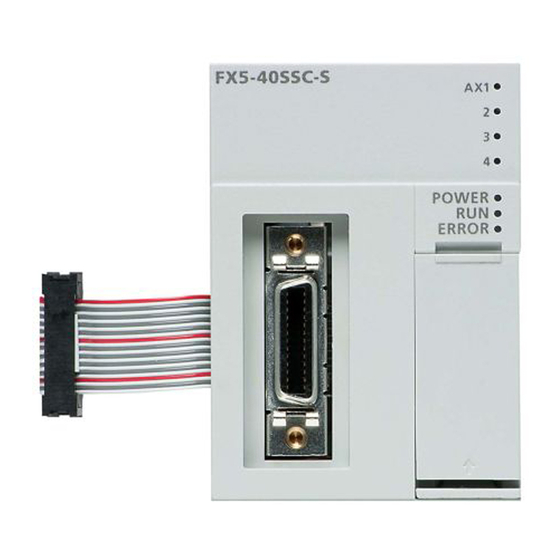
Page 20: Part Names
Part Names This section describes the part names of the FX5-CCLGN-MS. 2-I4.5 Mounting holes (10) (11) Name Description Modular jack for P1 (RJ45) A port for CC-Link IE TSN connection. Connects an Ethernet cable. (with cap) For wiring methods and wiring precautions, refer to the following. Page 85 WIRING Modular jack for P2 (RJ45) Same as the modular jack for P1 (RJ45) -
Page 21: Led Indication
LED indication The following table lists the LED indications. LED name Description color Green Indicates the operating status. On: Operating as a master station Off: Operating as a local station D LINK Green Indicates the cyclic transmission status. On: Cyclic transmission being performed Flashing: Cyclic transmission stopped Off: Disconnected P1 SD/RD... -
Page 22: Chapter 3 Procedures Before Operation
PROCEDURES BEFORE OPERATION This chapter describes the procedures before operation. Checking the specifications of the FX5-CCLGN-MS Check the specifications of the FX5-CCLGN-MS. ( Page 16 SPECIFICATIONS) Mounting the FX5-CCLGN-MS Mount the FX5-CCLGN-MS to the FX5 CPU module. For details, refer to the following. ... - Page 23 MEMO 3 PROCEDURES BEFORE OPERATION...
-
Page 24: Chapter 4 Functions
FUNCTIONS Function List The following tables list the functions of CC-Link IE TSN. The symbols in the availability column mean as follows: : Available, : Not available Cyclic transmission This function communicates data periodically among stations on the network using link devices. Function Description Availability... - Page 25 Transient transmission This function is used for data communications at any timing and has the following three types. Function Description Availability Reference Master Local station station Communications using a dedicated Reads/writes data from the master station or local station to Page 46 instruction devices in a CPU module of the local station using the...
- Page 26 RAS stands for Reliability, Availability, and Serviceability. This function improves overall usability of automated equipment. Function Description Availability Reference Master Local station station Slave station disconnection Stops data link of the station where an error occurred, and Page 60 Slave continues data link only for stations that are operating station normally.
- Page 27 Others Function Description Availability Reference Master Local station station "CC-Link IE TSN Parameter setting of a Sets parameters of slave stations (the number of points and Page 100 Configuration" slave station assignment of link devices) in the master station. Parameter window setting of a slave...
-
Page 28: Cyclic Transmission
Cyclic Transmission This function communicates data periodically among stations on the network using link devices. • The link devices can be assigned in "Network Configuration Settings" under "Basic Settings". ( Page 100 "CC-Link IE TSN Configuration" Window) • The link refresh is assigned in "Refresh Settings" under "Basic Settings". ( Page 93 Refresh settings) Cyclic transmission operates as follows with the communication mode set by the module parameter of the master station. -
Page 29: Communications Using Rx, Ry, Rwr, And Rww
Communications using RX, RY, RWr, and RWw This allows data communications in units of bits and in units of words between the master station and slave station. Master station and local stations ■At unicast mode 1:1 communications between the master station and each local station. Local stations do not communicate with each other. FX5 CPU module No.0 No.1... - Page 30 ■At multicast mode • The master station and local station send data on the line in multicast mode in each send range. • The authentication Class A local station communicates data in the same communication range as the authentication Class B local station.
- Page 31 Master station and remote stations ■At unicast mode 1:1 communications between the master station and each remote station. Remote stations do not communicate with each other. CPU module No.0 No.1 No.2 0000H 0000H 0000H 0000H No.1 mNo.1 mNo.2 Ø 001FH 001FH 001FH 0020H...
- Page 32 Coexistence of remote stations and local stations ■At unicast mode • 1:1 communications between the master station and each remote station, and between the master station and each local station. • Communications are not performed between remote stations, between local stations, and between a remote station and a local station.
- Page 33 ■At multicast mode • The master station and each local station can obtain data of all slave stations. • The authentication Class A local station communicates data in the same communication range as the authentication Class B local station. Class B Class B Class A No.0...
-
Page 34: Link Refresh
Link refresh This function automatically transfers data between the devices of the FX5-CCLGN-MS and the devices of the FX5 CPU module. FX5 CPU module FX5-CCLGN-MS Link refresh Link refresh Link refresh Link refresh Link refresh Link refresh Concept of the link refresh range (number of points) The link refresh is performed in the range set in "Refresh Settings"... - Page 35 Setting method The link refresh is assigned in "Refresh Settings" under "Basic Settings". ( Page 93 Refresh settings) Precautions ■Latched devices of the FX5 CPU module If data in latched devices of the FX5 CPU module are cleared to zero on a program when the FX5 CPU module is powered off and on or reset, the data may be output without being cleared to zero, depending on the timing of the cyclic data transfer processing and link refresh.
-
Page 36: Cyclic Data Assurance
Cyclic data assurance This function assures the cyclic data integrity in units of 32 bits or station-based units. : Assured, : Not assured Method Description Link refresh Access to buffer memory 32-bit data assurance Assures data in 32-bit units. Data is automatically assured by satisfying assignment conditions of link devices. - Page 37 Station-based block data assurance Integrity of the cyclic data is assured for each station by handshake between the FX5 CPU module and the FX5-CCLGN-MS for a link refresh. ■Setting Set station-based block data assurance under "Supplementary Cyclic Settings" in "Application Settings" of the master station. (...
- Page 38 Interlock program Data of more than 32 bits can be assured without using the station-based block data assurance setting. Use either of the following methods for interlocking: • Data assurance by handshake of the remote I/O • Data assurance by handshake of the remote register ■Data assurance by handshake of the remote I/O The following shows an example of sending data in W0 to W3 of the master station (station No.0) to W100 to W103 of the local station (station No.1).
- Page 39 • Program Sending station: Master station (station No.0) Classification Setting details Label to be defined Define global labels as shown below: Receiving station: Local station (station No.1) Classification Setting details Label to be defined Define global labels as shown below: •...
- Page 40 ■Data assurance by handshake of the remote register The following shows an example of sending data in W0 to W3 of the master station (station No.0) to W100 to W103 of the local station (station No.1). (B0 and B40 are used for a handshake to the FX5 CPU module.) No.0 No.1 FX5-CCLGN-MS...
- Page 41 Receiving station: Local station (station No.1) Classification Setting details Label to be defined Define global labels as shown below: • Program flow The master station checks that the send request bStartDirection (M0) is turned on, and transfers contents of uTransferFrom [0] to [3] to the send data W0 to ...
-
Page 42: Communication Cycle Coexistence
Communication cycle coexistence When slave stations with different communication cycles are included in the network, communicates data using multiple communication cycles according to each slave station. The time for each communication cycle is the total time of cyclic transmission, transient transmission, and system reservation time. -
Page 43: I/O Maintenance Settings
I/O maintenance settings When using cyclic transmission, set whether to hold or clear output on the sending side or input on the receiving side by using the following settings of (A), (B), and (C). ( Page 98 Supplementary cyclic settings) •... - Page 44 Output data hold/clear operation during CPU STOP The following figure shows the devices where the setting of "Output Hold/Clear Setting during CPU STOP" is enabled when the FX5 CPU module on the sending side changes from RUN to STOP. ■At unicast mode No.0 No.1 No.2...
- Page 45 ■At multicast mode No.0 No.1 No.2 No.3 No.1 No.1 No.1 No.1 No.2 No.2 No.2 No.3 No.3 No.3 No.1 No.1 No.1 No.1 No.2 No.2 No.2 No.3 No.3 No.3 No.1 No.1 No.1 No.1 No.2 No.2 No.2 No.3 No.3 No.3 No.1 No.1 No.1 No.1 No.2 No.2...
- Page 46 Input data hold/clear operation from the data link faulty station The following figure shows the devices where "Data Link Faulty Station Setting" is enabled when each station becomes faulty. ■At unicast mode No.3 No.0 No.1 No.2 No.1 No.1 No.2 No.2 No.3 No.3 No.1...
- Page 47 ■At multicast mode No.0 No.1 No.2 No.3 No.1 No.1 No.1 No.1 No.2 No.2 No.2 No.3 No.3 No.3 No.1 No.1 No.1 No.1 No.2 No.2 No.2 No.3 No.3 No.3 No.1 No.1 No.1 No.1 No.2 No.2 No.2 No.3 No.3 No.3 No.1 No.1 No.1 No.1 No.2 No.2...
-
Page 48: Transient Transmission
Transient Transmission This function is used for data communications at any timing and has the following three types. Page 46 Communications using a dedicated instruction Page 47 Communications using the SLMP Page 47 Communications using the engineering tool FX5-CCLGN-MS can communicate only in the same network. Communications using a dedicated instruction This type of the data communication is used to read/write data from the master station or local station to devices in a CPU module of the local station using the dedicated instructions. -
Page 49: Communications Using The Slmp
Communications using the SLMP This type of the data communication is used to read/write data from the external device, such as a personal computer or HMI (Human Machine Interface), to devices in the CPU module of the master station and local station and the buffer memory areas of the remote station via an SLMP. -
Page 50: Ethernet Connection
Ethernet Connection This function connects an Ethernet device to a module without interfering with CC-Link IE TSN. Connection with MELSOFT products Programming and monitoring of the programmable controller are performed via Ethernet using the engineering tool. This function enables remote control using long-distance connectivity and high-speed communications via Ethernet. The following table lists the methods of connecting the FX5-CCLGN-MS to MELSOFT products (such as engineering tool). - Page 51 ■Settings on the engineering tool side Set in the "Specify Connection Destination Connection" window. [Online] [Current Connection Destination] [Other Connection Method] [Other Connection Method (Open the Specify Connection Destination window)] 4 FUNCTIONS 4.4 Ethernet Connection...
- Page 52 Set "PC side I/F" to "Ethernet Board". Double-click "Ethernet Board", and open the "PC side I/ F Detailed Setting of Ethernet Board" window. Set the network number, station number, and protocol of the personal computer. TCP: A connection is established during communication. Since data is exchanged while checking that the data has correctly reached the communication destination, the data reliability can be ensured.
- Page 53 ■Searching modules on the network For a connection using a switching hub, a list of modules that can be searched for will appear by clicking the [Find] button on the detailed setting window. Search target modules are as follows. • FX5 CPU module connected to the same switching hub as the engineering tool •...
-
Page 54: Connection With Slmp-Compatible Devices
Connection with SLMP-compatible devices SLMP-compatible devices (such as a personal computer or a vision sensor) are connected to the FX5-CCLGN-MS. For details on SLMP, refer to the following. SLMP Reference Manual • To execute communications using SLMP, set the same communication speed for the connected station and access destination. -
Page 55: Security
Security This function ensures security according to the network environment by restricting access for each communication path to the FX5 CPU module. The following two access restriction methods can be used. Page 53 IP filter Page 55 Remote password IP filter This function identifies the IP address of the access source, and prevents unauthorized access. - Page 56 Setting method Set the IP address to be allowed or blocked in the "IP Filter Settings" window of "Security" under "Application Settings". ( Page 99 Security) A warning is displayed in the following cases. • When blocking the IP address of the slave station set in "Network Configuration Settings" under "Basic Settings" was attempted •...
-
Page 57: Remote Password
Remote password This function permits or prohibits access from the external device to the FX5 CPU module via the FX5-CCLGN-MS. This prevents unauthorized access to the FX5 CPU module from a remote location. The remote password is one method of preventing unauthorized access (such as program or data destruction) from an external device. - Page 58 Setting method Set a remote password on the "Remote Password Setting" window. [Navigation window] [Parameter] [Remote Password] Click the [Password] button, and register the remote password on the "Register Password" window. [Password] button Select the module for which the remote password is to be applied, and set "Intelligent Module No.".
- Page 59 Access permitted/prohibited processing operation The following describes the processing for permitting or prohibiting access from the external device to the FX5 CPU module with a remote password. ■Access permit processing (Unlock processing) The external device trying to communicate unlocks the remote password set for the connected FX5-CCLGN-MS. If the password is not unlocked, the FX5-CCLGN-MS to which the external device is connected prohibits access, so an error occurs in the external device.
- Page 60 ■Accessible station The station accessible from the external device when a remote password is set for the FX5 CPU module and the station that can unlock/lock the remote password are limited to those with the same network number. The following figure shows an example when the remote password is set for multiple stations in the system. Station 1-2 Station A FX5-CCLGN-MS...
- Page 61 Precautions The following describes the precautions when remote password is used. ■Setting of remote password for connection Set the remote password for the connection used for data communications with an external device that can execute the unlock/lock processing. ■When remote password is set for UDP/IP connection •...
-
Page 62: Ras
RAS stands for Reliability, Availability, and Serviceability. This function improves overall usability of automated equipment. Slave station disconnection Data link of the station where an error occurred is stopped, and the data link continues only for stations that are operating normally. -
Page 63: Ip Address Duplication Detection
IP address duplication detection When one network has stations with the same IP address, duplication is detected. Precautions When IP address duplication is detected in the master station (error codes: 1802H, 3021H), change the IP address of the corresponding station, and power off and on the master station, or reset it. Detection in each station When adding a slave station, if a station with the same IP address already exists, IP address duplication (error code: 2160H) is detected in a station to be added, and data link cannot be performed. -
Page 64: Time Synchronization
Time synchronization The time of slave stations is synchronized with the time synchronization source (CPU module of the master station). No.0 No.1 No.2 Setting method The time synchronization is set to the buffer memory. ( Page 194 Time synchronization) Set the same time zone to the CPU modules of the master and local stations. When the FX5-CCLGN-MS is used as the master station, do not connect time synchronization devices whose time synchronization priority is 0 to 15. -
Page 65: Others
Others Slave station parameter automatic setting This function saves parameters of the slave station in the master station, and automatically set the parameters when the slave station is connected or returned to the network. Slave station parameter automatic setting from the master station Parameters of the slave station set using the engineering tool are saved in the memory of the FX5 CPU module in the master station or the SD memory card by writing. -
Page 66: Chapter 5 System Configuration
SYSTEM CONFIGURATION CC-Link IE TSN is configured using Ethernet cables. ( Page 88 Ethernet cable) (1) FX5-CCLGN-MS (2) Inverter device (3) Remote I/O module (4) Ethernet device (such as a vision sensor) Precautions To connect modules on CC-Link IE TSN, a dedicated TSN switching hub may be required depending on parameter settings or the network topology used. - Page 67 Authentication Class setting From "Connection Device Information" under "Basic Settings" of the engineering tool, select either of the following items according to devices to be connected. Connected device System configuration Switching hub Standard information Authentication Class B Only Select this if the system is to be configured without connecting the TSN switching hub IEEE802.1AS authentication Class A device.
-
Page 68: 5.1 Structure Of Authentication Class B Devices And Ethernet Devices
Structure of Authentication Class B Devices and Ethernet Devices This section describes the system configuration when "Connection Device Information" under "Basic Settings" of the engineering tool is set to "Authentication Class B Only". When "Connection Device Information" under "Basic Settings" of the master station is set to "Authentication Class B Only", up to 61 devices (1 master station and 60 slave stations) can be connected. -
Page 69: Structure Of Unicast Mode
Structure of unicast mode This mode indicates the availability of connection with a network configuration device when "Communication Mode" under "Application Settings" is set to "Unicast". When the communication speed for the master station is set to 1Gbps The following table lists the availability of connection with a network configuration device when the communication speed for the master station is set to 1Gbps. -
Page 70: Structure Of Multicast Mode
Structure of multicast mode This mode indicates the availability of connection with a network configuration device when "Communication Mode" under "Application Settings" is set to "Multicast". When the communication speed for the master station is set to 1Gbps The following table lists the availability of connection with a network configuration device when the communication speed for the master station is set to 1Gbps. -
Page 71: Structure With Modules On Cc-Link Ie Tsn Only
Structure with modules on CC-Link IE TSN only Connection with modules on CC-Link IE TSN only ■Line topology The network is configured in a line topology. A TSN switching hub is not required. When an error occurs in a slave station, the stations connected after the faulty station will be disconnected. No.0 No.1 No.2... - Page 72 Connection with modules on CC-Link IE TSN with a communication speed of 100Mbps The following shows the network topologies when a CC-Link IE TSN module with a communication speed of 100Mbps is connected. ■Line topology In a structure where a module with a communication speed of 100Mbps exists, the FX5-CCLGN-MS cannot be connected. ■Star topology The network is configured in a star topology via a switching hub.
- Page 73 • When "Communication Mode" is set to "Multicast" and "Communication Speed" of the master station is set to "1Gbps", the slave stations with different communication speeds of 1Gbps and 100Mbps cannot be connected on the end side via the switching hub. Unicast mode Multicast mode No.0 (1Gbps)
- Page 74 • When the communication speed for the master station is 1Gbps, connection cannot be made if the total cyclic data size of all slave stations on the 100Mbps device side, including the devices with a communication speed of 100Mbps that form a boundary between the communication speed of 1Gbps and 100Mbps, exceeds 2K bytes.
-
Page 75: Structure With Modules On Cc-Link Ie Tsn And Ethernet Devices
Structure with modules on CC-Link IE TSN and Ethernet devices Connection with modules on CC-Link IE TSN and Ethernet devices ■Line topology The network with modules and devices is configured in a line topology. A TSN switching hub is not required. Connect Ethernet devices to the end of the network. -
Page 76: Structure Of Authentication Class B/A Devices And Ethernet Devices
Structure of Authentication Class B/A Devices and Ethernet Devices This section describes the system configuration when "Connection Device Information" under "Basic Settings" of the engineering tool is set to "Mixture of Authentication Class B/A or Authentication Class A Only". When "Connection Device Information" under "Basic Settings" of the master station is set to "Mixture of Authentication Class B/A or Authentication Class A Only", up to 61 devices (1 master station and 60 slave stations) can be connected. -
Page 77: Structure Of Unicast Mode
Structure of unicast mode This mode indicates the availability of connection with a network configuration device when "Communication Mode" under "Application Settings" is set to "Unicast". When the communication speed for the master station is set to 1Gbps The following table lists the availability of connection with a network configuration device when the communication speed for the master station is set to 1Gbps. -
Page 78: Structure Of Multicast Mode
Structure of multicast mode This mode indicates the availability of connection with a network configuration device when "Communication Mode" under "Application Settings" is set to "Multicast". When the communication speed for the master station is set to 1Gbps The following table lists the availability of connection with a network configuration device when the communication speed for the master station is set to 1Gbps. -
Page 79: Structure With Modules On Cc-Link Ie Tsn
Structure with modules on CC-Link IE TSN Connection with modules on CC-Link IE TSN only ■Line topology The network is configured in a line topology. • Up to eight authentication Class B devices can be connected to P1 or P2 of the master station. No.0 Class B Class B... - Page 80 • When "Communication Mode" is set to "Multicast", the local station cannot be connected to the authentication Class A remote station. Multicast mode No.3 No.4 No.0 No.1 Class A Class A Class B Class B No.2 Class B No.0: Master station No.1, No.4: Local station No.2, No.3: Remote station Class A: Authentication Class A device...
- Page 81 ■Coexistence of line and star topologies Line and star topologies can be mixed according to the availability of connection as described below. • Up to eight slave stations of authentication Class B can be connected to the transmission path from the master station to the authentication Class B device of the end.
- Page 82 Connection with modules on CC-Link IE TSN with a communication speed of 100Mbps This section describes the network topology when "Communication Speed" under "Application Settings" is set to "100Mbps". ■Line topology In a structure where a module with a communication speed of 100Mbps exists, the FX5-CCLGN-MS cannot be connected. ■Star topology The network is configured in a star topology via a switching hub.
- Page 83 • When "Communication Mode" is set to "Multicast" and the communication speed of the master station is set to "1Gbps", slave stations with different communication speeds of 1Gbps and 100Mbps cannot be connected on the end side via a switching hub. Multicast mode Multicast mode No.0...
-
Page 84: Structure With Modules On Cc-Link Ie Tsn And Ethernet Devices
Structure with modules on CC-Link IE TSN and Ethernet devices Connection with modules on CC-Link IE TSN and Ethernet devices ■Line topology The network with modules and devices is configured in a line topology. A TSN switching hub is not required. Up to eight modules on CC-Link IE TSN can be connected to P1 or P2 of the master station at the position indicated with (1). - Page 85 ■Coexistence of line and star topologies Line and star topologies can be mixed according to the availability of each connection. • Connect Ethernet devices at the end of line topology. • When connecting the Ethernet device in a star topology, connect the Ethernet device to the general-purpose switching hub. No.0 No.1 Class B...
-
Page 86: Precautions For System Configuration
Precautions for System Configuration Devices connected to the same network Do not connect the devices as described below. Doing so may cause the disconnection of all stations. • A module on CC-Link IE TSN and a device having network types other than an Ethernet device (such as CC-Link IE Controller Network and CC-Link IE Field Network) are connected to the same network. -
Page 87: Chapter 6 Wiring
WIRING This chapter describes the wiring methods, wiring products, and wiring precautions when using the FX5-CCLGN-MS. Power Supply Wiring Power connector layout (Green) (Black) (Red) Power supply wiring Master/local module Red Black Green Ground resistance of 24VDC 100 ohms or less (Grounding resistance: 100: or less) Grounding... -
Page 88: Cc-Link Ie Tsn Wiring
CC-Link IE TSN Wiring This section describes the wiring when using CC-Link IE TSN. Wiring methods The following describes connection and disconnection of the Ethernet cable. ■Connecting the cable Power off the FX5-CCLGN-MS and the external device. Push the Ethernet cable connector into the FX5-CCLGN-MS until it clicks. Pay attention to the connector's direction. Lightly pull it to check that it is securely connected. - Page 89 ■Precautions • The bending radius of the Ethernet cable is limited. For details, check the specifications of the Ethernet cable to be used. • Place the Ethernet cable in a duct or clamp them. If not, dangling cable may swing or inadvertently be pulled, resulting in damage to the module or cables or malfunction due to poor contact.
- Page 90 • IEEE 802.3 (1000BASE-T) • ANSI/TIA/EIA-568-B (Category 5e) Cables for CC-Link IE TSN are available from Mitsubishi Electric System & Service Co., Ltd. (Catalogs for cable are also available.) In addition, the connector processing of cable length is available for your preference. Please consult your local Mitsubishi representative.
-
Page 91: Chapter 7 Parameter Settings
PARAMETER SETTINGS This chapter describes the parameter settings required for communications between the FX5-CCLGN-MS and other stations. Setting Parameters Add the FX5-CCLGN-MS in the engineering tool. [Navigation window] [Parameter] [Module Information] Right-click [Add New Module] The required settings, basic settings, and application settings are included in the parameter settings. Select one of the settings from the tree on the following window. -
Page 92: Network No
Network No. Set the network number of the FX5-CCLGN-MS. Item Description Setting range Network No. Set the network number of the FX5-CCLGN-MS. 1 to 239 (Default: 1) Precautions Set a network number that does not duplicate any other network numbers. When a network number is duplicated in the same system, an error will occur in the CPU module. -
Page 93: Station No./Ip Address Setting
Station No./IP address setting Set the station number and IP address of the own station of the FX5-CCLGN-MS. Item Description Setting range Station No./IP Address Select whether to set the station number using the engineering tool or set the station number/IP •... -
Page 94: Basic Settings
Basic Settings Set the network configurations, refresh settings, or other parameters for the FX5-CCLGN-MS. : Can be set, : Cannot be set Item Description Availability Reference Master Local station station Network Configuration Set parameters of slave stations (the number of points and Page 100 "CC-Link IE TSN Settings assignment of link devices) in the master station. -
Page 95: Refresh Settings
Refresh settings Assign link refresh ranges between the following devices. • SB, SW, link devices (RX, RY, RWr, RWw) of the FX5-CCLGN-MS Devices of the FX5 CPU module Setting method The procedure for the refresh settings is as follows. Set the required items. - Page 96 Item Description Setting range For master stations For local stations ■Device name ■Device name 1 to 256 Link Side Set the link refresh ranges of RX, RY, RWr, and RWw. A maximum of 256 • RX, RY, RWr, RWw points can be set for the link refresh range of each. ( Page 32 Link •...
-
Page 97: Network Topology
Network topology Select the network topology type according to the actual network configuration. Setting is not required and can be left as "Line/Star" (default). Communication period setting Perform basic cycle setting and multiple cycle setting. • Basic cycle setting requires calculation of the communication cycle interval and cyclic transmission time. ( Page 215 Communication cycle intervals) •... -
Page 98: Connection Device Information
Connection device information Set the information of the connected device. Item Description Setting range Authentication Set the authentication Class of connected devices. • Authentication Class B only Class Setting • Mixture of Authentication Class B/A or Authentication Class A Only (Default: Authentication Class B only) Precautions In the case of "Authentication Class B Only"... -
Page 99: Application Settings
Application Settings Set the supplementary cyclic settings, transient transmission group number, and other settings for the FX5-CCLGN-MS. Item Description Reference Communication Speed Set the communication speed. Page 97 Communication speed Supplementary Cyclic Settings Set the station-based block data assurance and I/O maintenance settings. Page 98 Supplementary cyclic settings Transient Transmission Group No. -
Page 100: Supplementary Cyclic Settings
Supplementary cyclic settings Set the station-based block data assurance and I/O maintenance settings. Item Description Setting range Station-based Block Data Assurance Select whether to ensure data integrity of the data blocks being refreshed • Enable between the FX5 CPU module and the FX5-CCLGN-MS. ( Page 34 •... -
Page 101: Module Operation Mode
Module operation mode Set the mode for the FX5-CCLGN-MS. For details on the module communication test mode, refer to the following. Page 143 Module communication test Item Description Setting range Module Operation Mode Online • Online • Select this mode to connect the FX5-CCLGN-MS to the network for performing data •... -
Page 102: Cc-Link Ie Tsn Configuration" Window
"CC-Link IE TSN Configuration" Window Perform the parameter setting of slave stations, the detection of connected/disconnected devices, or others. [Navigation window] [Parameter] [Module Information] Target module [Module Parameter] [Basic Settings] [Network Configuration Settings] Parameter setting of a slave station Set parameters of slave stations (the number of points and assignment of link devices) in the master station. - Page 103 Simple Detailed Description Setting range display display RWw Setting Assign RWw/RWr points in increments of 4. ( Page 27 Communications • Number of points: 4 to 4096 using RX, RY, RWr, and RWw) • Start: 0H to FFCH RWr Setting Modules with settings provided by profile are automatically set from selected •...
-
Page 104: Connected/Disconnected Module Detection
Connected/Disconnected module detection Connected slave stations are detected and displayed on the "CC-Link IE TSN Configuration" window. Click the [Connected/Disconnected Module Detection] button. When the [Execute] button is clicked according to the instruction on the window, connected slave stations are detected and displayed on the "CC-Link IE TSN Configuration"... - Page 105 IP address verification Operation Display When station numbers of result detected slave stations are not set Detected slave stations are not in Connect Detected slave stations are added. (Settings other than "IP Address", A station number is the saved CC-Link IE TSN "STA#", and "Station Type"...
-
Page 106: Parameter Processing Of A Slave Station
Parameter processing of a slave station The processing is to read and save the parameters from the slave station, and to write the saved parameters to the slave station. Also, it automatically sets parameters of the slave station from the master station. ( Page 63 Slave station parameter automatic setting) [Navigation window] ... - Page 107 Item Description Target Module Information Information for the selected slave stations is displayed. Method selection Select processing to be executed for selected slave stations. • Parameter auto-setting: Automatically set contents of "Write Value/Setting Value" to the slave station. ( Page 63 Slave station parameter automatic setting) •...
-
Page 108: Command Execution To Slave Stations
Command execution to slave stations Commands to a slave station (Error clear request, Error history clear request) are executed. [Navigation window] [Parameter] [Module Information] Target module [Basic Settings] [Network Configuration Settings] Select and right-click the slave station, select "Command Execution of Slave Station" from "Online" to display the "Command Execution of Slave Station"... -
Page 109: Chapter 8 Dedicated Instruction
DEDICATED INSTRUCTION This chapter describes the transmission ranges and dedicated instructions that can be used in the FX5-CCLGN-MS. For details on dedicated instructions, refer to the following. MELSEC iQ-F FX5 Programming Manual (Instructions, Standard Functions/Function Blocks) Link dedicated instructions The following table lists the instructions used for transient transmission to or from programmable controllers on other stations. -
Page 110: Precaitions For Dedicated Instructions
Precaitions for Dedicated Instructions This section describes precautions when using dedicated instructions. Precautions for dedicated instructions (common) ■When changing data specified by dedicated instructions Do not change any data (such as control data) until execution of the dedicated instruction is completed. ■When the dedicated instruction is not completed Check whether the mode of the FX5-CCLGN-MS is set to online. -
Page 111: Chapter 9 Programming
PROGRAMMING This chapter describes programming and startup examples of CC-Link IE TSN. Precautions for Programming This section describes precautions to create CC-Link IE TSN programs. Cyclic transmission program For a cyclic transmission program, configure an interlock with the following module labels (link special relay (SB), link special register (SW)). -
Page 112: Communication Example Between The Master Station And Local Station
Communication Example between the Master Station and Local station The following system configuration is used to explain communication between the master station and local station. System configuration • CPU module: FX5 CPU module • Master/local module: FX5-CCLGN-MS (Intelligent module No.: 0000H to 001FH) No.0 No.1 No.2... - Page 113 ■RWr/RWw assignment Each of the following No.0 to No.2 represents a station number. No.0 is master station, and No.1 and No.2 are local stations. FX5 CPU module No.0 No.1 No.2 FX5 CPU module 0000H 0000H 0000H No.1 No.1 No.1 00FFH 00FFH 00FFH 0100H...
- Page 114 Multicast mode ■RX/RY assignment Each of the following No.0 to No.2 represents a station number. No.0 is master station, and No.1 and No.2 are local stations. FX5 CPU module No.0 No.1 No.2 FX5 CPU module 1000 1000 0000H 0000H 0000H No.1 No.1 No.1...
-
Page 115: Setting In The Master Station
Setting in the master station Connect the engineering tool to the FX5 CPU module on the master station and set the parameters. Set the FX5 CPU module as follows. [Project] [New] Click the [Setting Change] button to use the module label. 9 PROGRAMMING 9.2 Communication Example between the Master Station and Local station... - Page 116 Set the FX5-CCLGN-MS as follows. [Navigation window] [Parameter] [Module Information] Right-click [Add New Module] Click the [OK] button to add a module label of the FX5-CCLGN-MS. Set the items in "Required Settings" as follows. [Navigation window] [Parameter] [Module Information] [FX5-CCLGN-MS] [Required Settings] 9 PROGRAMMING 9.2 Communication Example between the Master Station and Local station...
- Page 117 Set the network configuration as follows. (Set the IP address for each station.) [Navigation window] [Parameter] [Module Information] [FX5-CCLGN-MS] [Basic Settings] [Network Configuration Settings] Click the [Close with Reflecting the Setting] button to close the "CC-Link IE TSN Configuration" window. Set the refresh settings as follows.
-
Page 118: Settings In The Local Stations
Settings in the local stations Connect the engineering tool to the FX5 CPU module on the local station and set parameters. Set the same setting for station No.1 and station No.2. Set the FX5 CPU module and add the module labels of the FX5 CPU module. The setting method of the FX5 CPU module and addition method of the module label are the same as those of the master station. - Page 119 Set the items in "Required Settings" as follows. [Navigation window] [Parameter] [Module Information] [FX5-CCLGN-MS] [Required Settings] • For station No.1 • For station No.2 Set the refresh settings as follows. Set the local stations with station No.1 and station No.2 to the same refresh settings. [Navigation window] ...
-
Page 120: Checking The Network Status
Checking the network status Once parameters are set for the master station and local station, check whether data links between the master station and local station is normally operating. For the check, use the CC-Link IE TSN/CC-Link IE Field diagnostics of the engineering tool. -
Page 121: Program Example (At Unicast Mode)
Program example (At unicast mode) This section describes a program example when "Communication Mode" under "Application Settings" is set to "Unicast". Master station (station No.0) Classification Label name Description Device Module label FX5CCLGN_1.bSts_DataLinkError_D Data link error status of own station SB0049 FX5CCLGN_1.bnSts_DataLinkError_Station_D[1] Data link status of each station (station No.1) - Page 122 ■Master station (station No.0) (11) Communication program with the local station (station No.1) (39) Communication program with the local station (station No.2) If no response is received for several cycles, 'Data link status of each station' (SW00B0 to SW00B7) is determined to be a cyclic transmission faulty station.
- Page 123 Local station (station No.1, station No.2) Classification Label name Description Device Module label FX5CCLGN_1.bSts_DataLinkError_D Data link error status of own station SB0049 Label to be defined Define global labels as shown below: • Local station (station No.1) • Local station (station No.2) ■Local station (station No.1) (8) Communication program with the master station (station No.0) 9 PROGRAMMING...
- Page 124 ■Local station (station No.2) (8) Communication program with the master station (station No.0) When "Communication Mode" is set to "Unicast", 'Data link status of each station' (SW00B0 to SW00B7) cannot be used as an interlock in the local station. Execute communications with other stations, taking account of the operating status in stations to be communicated.
-
Page 125: Program Example (At Multicast Mode)
Program example (At multicast mode) This section describes a program example when "Communication Mode" under "Application Settings" is set to "Multicast". Master station (station No.0) Classification Label name Description Device Module label FX5CCLGN_1.bSts_DataLinkError_D Data link error status of own station SB0049 FX5CCLGN_1.bnSts_DataLinkError_Station_D[1] Data link status of each station (station No.1) - Page 126 Local station (station No.1, station No.2) Classification Label name Description Device Module label FX5CCLGN_1.bSts_DataLinkError_D Data link error status of own station SB0049 FX5CCLGN_1.bnSts_DataLinkError_Station_D[1] Data link status of each station (station No.1) SW00B0.0 FX5CCLGN_1.bnSts_DataLinkError_Station_D[2] Data link status of each station (station No.2) SW00B0.1 Label to be defined Define global labels as shown below:...
- Page 127 ■Local station (station No.2) (8) Communication program with the master station (station No.0) (36) Communication program with the local station (station No.1) 9 PROGRAMMING 9.2 Communication Example between the Master Station and Local station...
-
Page 128: Examples Of Communication With Authentication Class A Remote Stations
Examples of Communication with Authentication Class A Remote Stations When "Communication Mode" is set to "Multicast", the local station cannot obtain data output by the authentication Class A remote station. Use the following communication examples so that the local station can obtain data output by the authentication Class A remote station. - Page 129 FX5 CPU module No.0 No.1 No.2 FX5 CPU module 1000 0000H 0000H 0000H 1000 No.1 No.1 ←No.1 No.1 No.1 1177 007FH 007FH 007FH 1177 1200 0080H 0080H 1200 No.2 No.2 No.2 No.2 1377 00FFH 00FFH 1377 0100H 1400 No.2 No.2 017FH 1577 1000...
-
Page 130: Setting In The Master Station
■RWr/RWw assignment Each of the following No.0 to No.2 represents a station number. • No.0: Master station (station No.0) • No.1: Remote station (station No.1) • No.2: Local station (station No.2) FX5 CPU module No.0 No.1 No.2 FX5 CPU module 0000H 0000H 0000H... - Page 131 Set the FX5-CCLGN-MS as follows. [Navigation window] [Parameter] [Module Information] Right-click [Add New Module] Click the [OK] button to add a module label of the FX5-CCLGN-MS. 9 PROGRAMMING 9.3 Examples of Communication with Authentication Class A Remote Stations...
- Page 132 Set the items in "Required Settings" as follows. [Navigation window] [Parameter] [Module Information] [FX5-CCLGN-MS] [Required Settings] Set the items in "Basic Settings" as follows. [Navigation window] [Parameter] [Module Information] [FX5-CCLGN-MS] [Basic Settings] 9 PROGRAMMING 9.3 Examples of Communication with Authentication Class A Remote Stations...
- Page 133 Set the network configuration as follows. (Set the IP address for each station.) [Navigation window] [Parameter] [Module Information] [FX5-CCLGN-MS] [Basic Settings] [Network Configuration Settings] Click the [Close with Reflecting the Setting] button to close the "CC-Link IE TSN Configuration" window. Set the refresh settings as follows.
-
Page 134: Remote Station Settings
Set the items in "Application Settings" as follows. [Navigation window] [Parameter] [Module Information] [FX5-CCLGN-MS] [Application Settings] Click the [Apply] button. Write the set parameters to the FX5 CPU module on the master station. Then, reset the FX5 CPU module or power off and on the system. -
Page 135: Settings In The Local Stations
Settings in the local stations Connect the engineering tool to the FX5 CPU module on the local station and set parameters. Set the FX5 CPU module and add the module labels of the FX5 CPU module. The setting method of the FX5 CPU module and addition method of the module label are the same as those of the master station. - Page 136 Set the refresh settings as follows. [Navigation window] [Parameter] [Module Information] [FX5-CCLGN-MS] [Basic Settings] [Refresh Settings] Set the items in "Application Settings" as follows. [Navigation window] [Parameter] [Module Information] [FX5-CCLGN-MS] [Application Settings] Click the [Apply] button.
-
Page 137: Checking The Network Status
Checking the network status After starting up the system, check whether data link can be normally performed. For the check, use the CC-Link IE TSN/CC- Link IE Field diagnostics of the engineering tool. Connect the engineering tool to the FX5 CPU module on the master station. Start the CC-Link IE TSN/CC-Link IE Field diagnostics. -
Page 138: Program Examples
Program examples The following is a program example of communications between the authentication Class B master station (station No.0), authentication Class A remote station (station No.1), and local station (station No.2). Master station (station No.0) Classification Label name Description Device Module label FX5CCLGN_1.bSts_DataLinkError_D Data link error status of own station... - Page 139 Local station (station No.2) Classification Label name Description Device Module label FX5CCLGN_1.bSts_DataLinkError_D Data link error status of own station SB0049 Label to be defined Define global labels as shown below: • Local station (station No.2) ■Local station (station No.2) (8) Communication program with the master station (station No.0) and the remote station (station No.1) 9 PROGRAMMING 9.3 Examples of Communication with Authentication Class A Remote Stations...
-
Page 140: Chapter 10 Troubleshooting
TROUBLESHOOTING This chapter describes troubleshooting of CC-Link IE TSN. 10.1 Checking with LED This section describes troubleshooting with LEDs. When the RUN LED turns off When the RUN LED turns off after powering on the FX5-CCLGN-MS, check the following. Check item Action Is the FX5-CCLGN-MS mounted correctly? Securely mount the FX5-CCLGN-MS on the FX5 CPU module. - Page 141 When the D LINK LED turns off or is flashing When the D LINK LED turns off or is flashing, check the following. Check item Action Is the master station operating normally? • If an error occurs in the FX5 CPU module on the master station, eliminate the cause of the FX5 CPU module error.
- Page 142 When the L ER LED turns on When the L ER LED turns on, check the following. Check item Action Are the Ethernet cables used normally? • Use an Ethernet cable that conforms to the standard. ( Page 16 Performance Specifications of CC-Link IE TSN) •...
-
Page 143: Checking The Module Status
10.2 Checking the Module Status Module diagnostics The following items can be checked in the "Module Diagnostics" window for the FX5-CCLGN-MS. Item Description [Error Information] tab Displays the details of the errors currently occurring and the corrective actions for these errors. "-"... - Page 144 Module Information List The LED information and individual information of the FX5-CCLGN-MS are displayed in the [Module Information List] tab. Item Description LED information Displays the LED status of the FX5-CCLGN-MS. Individual Station Type Displays the station type set for the selected module. information Network No.
-
Page 145: Module Communication Test
Module communication test The module communication test checks the hardware of the FX5-CCLGN-MS. The module hardware is checked when the communication using the FX5-CCLGN-MS is unstable. The following table lists the tests performed. Test item Description Internal self-loopback test Checks whether the communication function of the module can be performed normally. External self-loopback test Checks whether the communication can be performed normally with the Ethernet cable connected between two connectors of the module. -
Page 146: Checking The Network Status
10.3 Checking the Network Status The network status is checked and troubleshooting is performed by using the CC-Link IE TSN/CC-Link IE Field diagnostics to check the network status and error definition and by performing an operation test to check communications. CC-Link IE TSN/CC-Link IE Field diagnostics For CC-Link IE TSN, perform status monitoring, operation tests, or others. - Page 147 Function Function Description Connection destination of Reference type engineering tool Master Local station station Operation test/ Communication Test • This test specifies the network number and Page 152 execution station number or the IP address to check Communication test function whether transient transmission can be performed from the connected station (own...
- Page 148 Usage methods The following describes how to use the CC-Link IE TSN/CC-Link IE Field diagnostics. Connect the engineering tool to the FX5 CPU module. If a slave station cannot be monitored due to an error such as Ethernet cable disconnection, directly connect the engineering tool to the slave station.
- Page 149 Select the station to be diagnosed from "Select Station" or in the network map. Disconnected Network map station • An icon indicating an error is displayed on the module icon of the station where an error occurs. • A disconnected station that has performed data link is indicated with the "Disconnected Station" icon in the network map. However, a disconnected station in following case is displayed on the right end of the area.
- Page 150 "CC-Link IE TSN/CC-Link IE Field Diagnostics" window Network map Item Description Select Module The FX5-CCLGN-MS under diagnostics is displayed. Diagnostics [Change Module] Allows to change the target FX5-CCLGN-MS when multiple FX5-CCLGN-MSs are mounted. Destination button When two FX5-CCLGN-MSs with the same network number are mounted on the FX5 CPU module, the FX5-CCLGN- MS which is closer to the FX5 CPU module is always diagnosed, regardless of setting.
- Page 151 Network map ■Icon The module type and station number are displayed with an icon. • Click: Selection • Right-click: Executes tests or debugging. • keys on the keyboard: Move the focus to the module to be diagnosed, and determine it with the ...
- Page 152 In the following cases, the network map is displayed differently from the actual connection status. Connection status Display of the network map Two stations are connected through a switching hub. Branches are not displayed in the network map. TSN switching hub No.0 No.1 Switching hubs are in cascade connection.
- Page 153 Selected Station Communication Status Monitor Status of the station selected in "Network Status" is displayed. ■When a station where an error has occurred is selected Description Indicates the station number and operating status. • Station number No error (light blue): Normal operation •...
-
Page 154: Communication Test
Communication test This function checks if transient transmission data can be properly routed from the own station to the communication target. Depending on selection for "Communication Method" ("Network No./Station No." or "IP Address"), the range that can be checked may vary. Selection of "Communication Communication target of transient transmission Method"... -
Page 155: Remote Operation
Remote operation This function executes remote operations (such as RUN, STOP, and RESET operations) to the station selected on the "CC- Link IE TSN/CC-Link IE Field Diagnostics" window, from the engineering tool. (Remote operation for slave stations is available only for RESET.) The displayed window varies depending on the station selected. -
Page 156: Troubleshooting By Symptom
10.4 Troubleshooting by Symptom This section describes troubleshooting by symptom. Perform the troubleshooting by symptom when a data link cannot be performed with the target station even though no error occurs in the FX5-CCLGN-MS. If an error has occurred in the FX5- CCLGN-MS, identify the error cause using the engineering tool. - Page 157 When transient transmission cannot be performed The following lists the actions to be taken if transient transmission cannot be performed with the target station, and the engineering tool cannot perform monitoring. Check item Action Is the D LINK LED of the FX5-CCLGN-MS flashing or turned on? Perform troubleshooting to be performed when the D LINK LED turns off.
- Page 158 When a station is disconnected from the network The following is the action to be taken when a station in data link is disconnected. Check item Action Is the ambient temperature for the module outside the specified range? Keep the ambient temperature within the specified range by taking action such as removing heat source.
- Page 159 When communication with an SLMP-compatible device cannot be performed When communication with an SLMP-compatible device cannot be performed, check the following items. Check item Action Has the connection with the external device been opened normally? • If the connection with the external device is not opened, perform the open processing.
- Page 160 When communications with Ethernet devices cannot be performed When communications (CC-Link IE TSN/CC-Link IE Field diagnostics, transient transmission, remote password, or communication test) with Ethernet devices cannot be performed, check the following items. Check item Action Is the firewall or proxy server setting enabled on the Ethernet device? Check and correct the firewall and proxy server settings on the Ethernet device such as checking if a response to the PING command (ICMP echo request) is disabled.
-
Page 161: List Of Error Codes
10.5 List of Error Codes The following table lists the error codes, error definitions and causes, and actions for the errors that occur in the processing for data communication between the FX5-CCLGN-MS and external devices or occur by processing requests from the FX5 CPU module on the own station. - Page 162 Error Error definition and causes Action Detailed code information 1 Detailed information 2 ■Operation source 1802H During data link, overlapping IP addresses Change the IP address of devices with a duplicated IP address. have been detected. information • IP address ■IP address duplication information...
- Page 163 Error Error definition and causes Action Detailed code information 1 Detailed information 2 1805H • The total cyclic data size of all slave Check the connection and setting on the end side of the station shown in ■Own station stations on the authentication Class A detailed information 2 based on the error definition and cause and take the information device side at the boundary between...
- Page 164 Error Error definition and causes Action Detailed code information 1 Detailed information 2 ■Parameter 300AH • The combination of the local station • Check the firmware versions of the master station and local station. If the firmware version and the master station combination is incorrect, update the firmware version of the older local information firmware version is incorrect.
- Page 165 Error Error definition and causes Action Detailed code information 1 Detailed information 2 3013H The value set in "Transient Transmission Set "Communication Period Interval Setting" and "Cyclic Transmission ■ Time" in "Communication Period Setting" Time" so that the value of "Transient Transmission Time" in "Communication ■Communication under "Basic Settings"...
- Page 166 Error Error definition and causes Action Detailed code information 1 Detailed information 2 ■Operation source 3021H At startup of data link, IP address Correct the IP addresses of the slave stations. duplication among slave stations has been information detected. • IP address ■IP address duplication information...
- Page 167 Error Error definition and causes Action Detailed code information 1 Detailed information 2 3C01H A hardware failure has been detected. • Take measures to reduce noise. • Reset the CPU module, and run it again. If the same error occurs again even after taking the above, the possible cause is a hardware failure of the module or extension cable.
- Page 168 Error Error definition and causes Action Detailed code information 1 Detailed information 2 C032H The external device does not send an ACK • Since there may be congestion of packets on the line, send data after a response in the TCP/IP communications. certain period of time.
- Page 169 Error Error definition and causes Action Detailed code information 1 Detailed information 2 C057H The request data length of the SLMP Check and correct the text or request data length, and send the SLMP message does not match the number of message to the Ethernet-equipped module again.
- Page 170 Error Error definition and causes Action Detailed code information 1 Detailed information 2 C06FH The network number of request destination • If the 3E or 4E frame is used at SLMP, check that there is no error for the specified by the SLMP request message is network number of the request destination and station number.
- Page 171 Error Error definition and causes Action Detailed code information 1 Detailed information 2 C1A4H • There is an error with the command, • Correct the command, subcommand, or request destination module I/O subcommand, or request destination number specified by SLMP message. module I/O number specified by the •...
- Page 172 Error Error definition and causes Action Detailed code information 1 Detailed information 2 C901H The size of the request data to the external Correct the size of the request data or response data to within 1500 bytes. device or response data from the external device exceeds the range supported for communications.
- Page 173 Error Error definition and causes Action Detailed code information 1 Detailed information 2 D205H The target station number of transient Correct the target station number at the transient request source, and retry transmission is incorrect. the operation. D20AH The target network number of transient Correct the target network number at the transient request source, and retry transmission is incorrect.
- Page 174 Error Error definition and causes Action Detailed code information 1 Detailed information 2 D249H The target station CPU type of the Correct the CPU type of the target station at the request source of the dedicated instruction is incorrect. dedicated instruction, and retry the operation.
- Page 175 Error Error definition and causes Action Detailed code information 1 Detailed information 2 D256H The execution or error completion type of • Correct the execution or error completion type in the control data, and the dedicated instruction is incorrect. retry the operation.
- Page 176 Error Error definition and causes Action Detailed code information 1 Detailed information 2 D605H Parameter error • Write the network parameter to the CPU module again. • If the error occurs again even after taking the above, please consult your local Mitsubishi representative.
- Page 177 Error Error definition and causes Action Detailed code information 1 Detailed information 2 D61DH Parameter error (device overlap error • Write the network parameter to the CPU module again. (RY)) • Execute again after correcting the offset or size of the slave station link device in the setting data.
- Page 178 Error Error definition and causes Action Detailed code information 1 Detailed information 2 D644H Parameter error (cyclic transmission time • Write the network parameter to the CPU module again. setting) • Execute again after correcting the cyclic transmission time in the setting data.
- Page 179 Error Error definition and causes Action Detailed code information 1 Detailed information 2 D654H System error Please consult your local Mitsubishi representative. D655H Network addresses of the master station Correct the IP address setting of the master station or slave stations. and slave stations are incorrect.
- Page 180 Error Error definition and causes Action Detailed code information 1 Detailed information 2 D90CH The communication destination specified • Correct "Target Station" of communication test, and retry the operation. for the communication test is incorrect. • Do not execute the communication test for own station and relay sending station.
-
Page 181: List Of Parameter Numbers
10.6 List of Parameter Numbers The following table lists the parameter numbers displayed in "Module Diagnostics". If there is an error in the parameter settings and the parameter number is displayed, the corresponding parameter can be identified. It is displayed in "Detailed information" in the [Error Information] tab in the "Module Diagnostics" window of the FX5-CCLGN- MS. -
Page 182: Event List
10.7 Event List This section lists the events which occur in CC-Link IE TSN. The event history is displayed when the [Event History] button in the [Error Information] tab in the "Module Diagnostics" window of the FX5-CCLGN-MS is clicked. ( Page 141 Error Information) System Event Description... -
Page 183: Appendices
APPENDICES Appendix 1 External Dimensions The following shows the external dimensions of the FX5-CCLGN-MS. 2-I4.5 Mounting holes (Unit: mm) • Weight: Approx. 0.3kg APPX Appendix 1 External Dimensions... -
Page 184: Appendix 2 Standard Compliant Model
Conformity of the entire machinery manufactured by using this product to the following directives is not guaranteed. The manufacturer of the machinery must determine whether to declare conformity to the EMC Directive and the Low Voltage Directive (LVD). For details, consult Mitsubishi Electric separately. Measures to comply with the EMC Directive... -
Page 185: Precautions For Compliance With Ec Directive
Attach the ferrite core with each cable wrapped around it three times at a location within approximately 200mm from the terminal block of the power cable and connector. (Ferrite core used for testing by Mitsubishi Electric: E04SR401938 manufactured by SEIWA ELECTRIC MFG. CO., LTD.) Precautions when using an Ethernet port Use a double shielded twisted pair cable as the 1000BASE-T cable. -
Page 186: Appendix 3 Buffer Memory
Appendix 3 Buffer Memory The buffer memory is used to exchange data between the FX5-CCLGN-MS and the FX5 CPU module. Buffer memory values are reset to default when the FX5 CPU module is reset or the system is powered off. List of buffer memory addresses : Same as the address of P1 Name... - Page 187 Name Read, write Address Address Address Address (decimal) (hexadecimal) (decimal) (hexadecimal) 25856 to 25857 6500H to 6501H RWw offset/size Station No.0 RWw offset Read information 25858 to 25859 6502H to 6503H Station No.0 RWw size Read ...
- Page 188 Name Read, write Address Address Address Address (decimal) (hexadecimal) (decimal) (hexadecimal) 52228 to 52229 CC04H to CC05H 60164 to 60165 EB04H to EB05H P1: Own node Own node IP address Read setting status 52230 to 52237 CC06H to CC0DH 60166 to 60173 EB06H to EB0DH System area storage area...
- Page 189 Name Read, write Address Address Address Address (decimal) (hexadecimal) (decimal) (hexadecimal) 52992 to 52993 CF00H to CF01H 60928 to 60929 EE00H to EE01H Status for each Received packet total count Read protocol (IP 52994 to 52995 CF02H to CF03H 60930 to 60931 EE02H to EE03H Received packet checksum Read...
- Page 190 Name Read, write Address Address Address Address (decimal) (hexadecimal) (decimal) (hexadecimal) 53292 D02CH 61228 EF2CH P1: Area for System area sending/ 53293 D02DH 61229 EF2DH RECV instruction execution Read receiving request instructions 53294 to 53319 D02EH to D047H 61230 to 61255 EF2EH to EF47H System area P2: System area...
-
Page 191: Details Of Buffer Memory Addresses
Details of buffer memory addresses Module information area ■Latest error code (Un\G29) The error code for the latest error that occurred in the FX5-CCLGN-MS is stored. (0 is stored in normal condition.) For details on error codes, refer to the following. Page 159 List of Error Codes ■Unique code (Un\G30) The unique code (6988H) of the FX5-CCLGN-MS is stored. - Page 192 ■Remote output (RY) (Un\G1280 to Un\G2303) The RY value is stored. The RY start number and number of points for each station number can be checked by the RY offset/ size information (Un\G24832 to Un\G25855). ( Page 191 RY offset/size information) Address Un\G1280 ...
- Page 193 Timeslot information ■Timeslot 0 information (Un\G23552 to Un\G23567) Cycle start offset (ns, s unit) of Timeslot 0 and cycle end offset (ns, s unit) are stored. Address Name Description Un\G23552 to Un\G23553 Cycle start offset (ns unit) The ns digits of cycle start offset are stored. Stored range: 0 to 999999999ns Un\G23554 Cycle start offset (s unit)
- Page 194 RWw offset/size information ■RWw offset/size information (Un\G25856 to Un\G26879) The start number and the number of points of RWw for each station are stored. Address Description Un\G25856 to Un\G25857 Station No.0 offset Un\G25858 to Un\G25859 Station No.0 size (in units of words) Un\G25860 to Un\G25861 Station No.1 offset Un\G25862 to Un\G25863...
- Page 195 Own station information The information of the own station on the network is stored. ■Own station (network card) information (Un\G28160 to Un\G28167) Address Name Description Un\G28160 Manufacturer code The FX5-CCLGN-MS information of the own station is stored. (Also used in the CLPA conformance test.) Un\G28161 Model type (Updated even if set as an error invalid station.)
- Page 196 Time synchronization ■Time distribution interval setting of the CPU module (Un\G51200) This setting specifies the interval for distributing the clock time of the CPU module on the same system as the master module from the master station to slave stations. When the setting is changed, the new setting value is enabled after the interval of the distribution operating with the old setting value has elapsed.
- Page 197 Own node setting status storage area ■Own node IP address (Un\G52228 to Un\G52229) The setting values of the IP address are stored. Range: 1H to DFFFFFFEH ■Subnet mask (Un\G52238 to Un\G52239) The setting values of the subnet mask are stored. Range: 1H to FFFFFFFFH 0: No setting ■Default gateway IP address (Un\G52242 to Un\G52243)
- Page 198 Connection status storage area ■Latest error code after the 2nd connection of MELSOFT transmission port (TCP/IP) (Un\G52452 to Un\G52458) The latest error code of the 2nd to 8th connection of the MELSOFT transmission port (TCP/IP) is stored. ■Latest error code after the 2nd connection of SLMP transmission port (TCP/IP) (Un\G52580 to Un\G52586) The latest error code of the 2nd to 8th connection of the SLMP transmission port (TCP/IP) is stored.
- Page 199 Status for each protocol (ICMP packet) ■Received packet total count (Un\G53032 to Un\G53033, Un\G60968 to Un\G60969) The status is counted from 0 to 4294967295 (FFFFFFFFH). ■Received packet checksum error discard count (Un\G53034 to Un\G53035, Un\G60970 to Un\G60971) The status is counted from 0 to 4294967295 (FFFFFFFFH). ■Sent packet total count (Un\G53036 to Un\G53037, Un\G60972 to Un\G60973) The status is counted from 0 to 4294967295 (FFFFFFFFH).
- Page 200 Own node operation status storage area (switching hub connection information area) ■Communication mode (Un\G53183, Un\G61119) • 0: Half-duplex • 1: Full-duplex ■Connection status (Un\G53184, Un\G61120) • 0: Switching hub not connected/disconnected • 1: Switching hub connected ■Communication speed (Un\G53185, Un\G61121) •...
- Page 201 Remote password function monitoring area ■Auto-open UDP port continuous unlock failure count (Un\G59640, Un\G67576) The mismatch count of remote password at unlock of the auto-open UDP port is stored. The count is cleared when the password matches. Range: 0 to 65535 (Values of 65535 or more are not changed) ■MELSOFT transmission port (UDP/IP) continuous unlock failure count (Un\G59641, Un\G67577) The mismatch count of remote password at unlock of the MELSOFT transmission port (UDP/IP) is stored.
-
Page 202: Appendix 4 List Of Link Special Relay (Sb)
Appendix 4 List of Link Special Relay (SB) The link special relay (SB) is turned on/off depending on various factors during data link. Any error status of the data link can be checked by using or monitoring it in the program. Application of link special relay (SB) By using link special relay (SB), the status of CC-Link IE TSN can be checked from HMI (Human Machine Interfaces) as well as the engineering tool. - Page 203 List of link special relay (SB) The following table lists the link special relay areas (SB) when they are assigned from SB0000 to SB0FFF. Do not turn on or off areas whose numbers are not in the following list. Doing so may cause malfunction of the programmable controller system.
- Page 204 Name Description Availability Master Local station station Unicast Multicast mode mode SB0049 Data link error status of own Stores the data link error status of the own station. station Off: Normal On: Error When this relay is turned on, the cause of the error can be checked with 'Cause of data link stop' (SW0049).
- Page 205 Name Description Availability Master Local station station Unicast Multicast mode mode SB0074 Reserved station Stores the status of reserved station specification by parameter. The specification status station number of the station set as a reserved station can be checked with 'Reserved station setting status' (SW00C0 to SW00C7).
- Page 206 Name Description Availability Master Local station station Unicast Multicast mode mode SB00D0 Error invalid station setting Set whether an error invalid station is set. current status Off: No setting On: Set When this relay is turned on, the status of each station can be checked with 'Error invalid station setting status' (SW00D0 to SW00D7).
- Page 207 Name Description Availability Master Local station station Unicast Multicast mode mode SB0110 CPU minor error status of For local stations, stores the minor error occurrence status of the each station CPU module on each station. For remote stations, stores the minor error occurrence status of each station.
-
Page 208: Appendix 5 List Of Link Special Register (Sw)
Appendix 5 List of Link Special Register (SW) The link special register (SW) stores the information during data link as a numerical value. Faulty areas and causes can be checked by using or monitoring the link special register (SW) in programs. Application of link special register (SW) By using link special register (SW), the status of CC-Link IE TSN can be checked from HMI (Human Machine Interfaces) as well as the engineering tool. - Page 209 List of link special register (SW) The following table lists the link special register areas (SW) when they are assigned from SW0000 to SW0FFF. Do not write any data to an area whose number is not on the following list. Doing so may cause malfunction of the programmable controller system.
- Page 210 Name Description Availability Master Local station station Unicast Multicast mode mode SW004B CPU status of own station Stores the status of the FX5 CPU module on the own station. 00H: No CPU module mounted 01H: STOP (normal) 02H: STOP (moderate/major error) 03H: STOP (minor error) 04H: RUN (normal)
- Page 211 Name Description Availability Master Local station station Unicast Multicast mode mode SW0073 Cyclic transmission time Stores the cyclic transmission time calculated by the number of (calculation value) slave stations and the number of points that are set in "Network Configuration Settings"...
- Page 212 Name Description Availability Master Local station station Unicast Multicast mode mode SW00C8 Parameter setting status Stores the status of parameter settings. 0: No parameter setting SW00CF 1: Parameter set (Conditions) • Stations that surpass the maximum station number are ignored. ...
- Page 213 Name Description Availability Master Local station station Unicast Multicast mode mode SW0199 Link dedicated instructions Stores the processing results of the link dedicated instruction that processing result CH4 used channel 4 of the own station. 0: Completed successfully 1 or greater: Completed with an error (Error code is stored.) SW019A Link dedicated instructions...
-
Page 214: Appendix 6 Processing Time
Appendix 6 Processing Time The transmission delay time of CC-Link IE TSN consists of the time components below. ( Page 213 Cyclic transmission delay time) (1) Master station sequence scan time + (2) Communication cycle interval (cyclic data transfer processing time) + (3) Slave station processing time •... -
Page 215: Cyclic Transmission Delay Time
Cyclic transmission delay time This section shows how to calculate the following cyclic transmission delay time. • The time between the transmission source CPU module device turning on or off and the transmission destination CPU module device turning on or off •... - Page 216 Master station local station When data is transmitted from the master station to a local station as follows: • Master station (RY) local station (RX) • Master station (RWw) local station (RWr) Calculation value Station-based block data assurance No station-based block data assurance If LS <...
-
Page 217: Communication Cycle Intervals
Communication cycle intervals The minimum value of the communication cycle interval (cyclic data transfer processing time) is calculated by the following calculation formula. The parts enclosed in double quotation marks (" ") in the table of Variable are the values set for "Network Configuration Settings"... - Page 218 Unicast mode ■Calculation formula and Communication cycle interval [ns]= + or 250000, whichever is larger Round up values of that are less than 1s. • : Cyclic transmission speed [ns] is the largest value in the following calculation formulas. Calculation formula {(50n1)+(16n2)+ndm}8+(Sn-1)830+14000+nh {(30n1)+(16n2)+ndm}4+(1661n1)+(Sn-1)830+14300+nh...
- Page 219 *1 The switching hub delay time changes depending on the switching hub model and settings. *2 This is the slave station with the largest calculation value when, for each slave station, ("RX setting"/8) + ("RWr setting" 2) is calculated. *3 When the FX5-CCLGN-MS is used as a local station, add a value of p4 to the "Communication Period Setting"...
- Page 220 Multicast mode ■Calculation formula and Communication cycle interval [ns]= + or 250000, whichever is larger Round up values of that are less than 1s. • : Cyclic transmission speed [ns] is the largest value in the following calculation formulas. Calculation formula {(50(n1r+n1l))+(16(n2r+n2l))+(ndmr+ndml)}8+(Sn-1)830+14000+nh+(No.3 or No.4, whichever is larger) {(30(n1r+n1l))+(16(n2r+n2l))+(ndmr+ndml)}4+(1661(n1r+n1l))+(Sn-1)830+14300+nh+(No.3 or No.4, whichever is larger)
- Page 221 Name of variable Description Station-based block data assurance setting Assured: 1 Not assured: 1.55 When used as a master station: Sn 10000 When used as a local station: 0 *1 The switching hub delay time changes depending on the switching hub model and settings. *2 A sum of values starting from the smallest value set in "Start"...
-
Page 222: Appendix 7 Port Number
Appendix 7 Port Number A port number for the system cannot be specified. Port number Applications Decimal Hexadecimal 20 to 21 14H to 15H For system 161 to 162 A1H to A2H For system 5000 1388H For system 5001 1389H MELSOFT transmission port (UDP/IP) 5002 to 5009 138AH to 1391H... - Page 223 MEMO APPX Appendix 7 Port Number...
-
Page 224: Index
INDEX 0 to 9 ....34 ....107 32-bit data assurance Other dedicated instructions . - Page 225 MEMO...
-
Page 226: Revisions
Japanese manual number: SH-082214-B This manual confers no industrial property rights or any rights of any other kind, nor does it confer any patent licenses. Mitsubishi Electric Corporation cannot be held responsible for any problems involving industrial property rights which may occur as a result of using the contents noted in this manual. -
Page 227: Warranty
WARRANTY Please confirm the following product warranty details before using this product. 1. Gratis Warranty Term and Gratis Warranty 2. Onerous repair term after discontinuation of production Range If any faults or defects (hereinafter "Failure") found to be Mitsubishi shall accept onerous product repairs for the responsibility of Mitsubishi occurs during use of the seven (7) years after production of the product is product within the gratis warranty term, the product shall... -
Page 228: Trademarks
TRADEMARKS Microsoft and Windows are either registered trademarks or trademarks of Microsoft Corporation in the United States and/or other countries. All other company names and product names used in this manual are either trademarks or registered trademarks of their respective companies. - Page 230 SH(NA)-082215ENG-B(2009)MEE MODEL: FX5-U-CCIETSN-E MODEL CODE: 09R739 When exported from Japan, this manual does not require application to the Ministry of Economy, Trade and Industry for service transaction permission. HEAD OFFICE: TOKYO BUILDING, 2-7-3 MARUNOUCHI, CHIYODA-KU, TOKYO 100-8310, JAPAN Specifications are subject to change without notice.