Panasonic HG-S Series User Manual
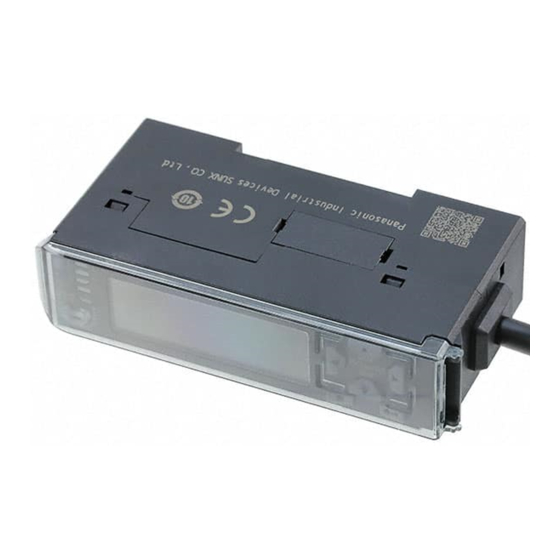
Contact-type digital displacement sensor
Hide thumbs
Also See for HG-S Series:
- User manual (198 pages) ,
- Instruction manual (2 pages) ,
- User manual (176 pages)

Related Manuals for Panasonic HG-S Series


Summary of Contents for Panasonic HG-S Series
- Page 1 Contact-Type Digital Displacement Sensor HG-S Series User's Manual WUME-HGS-6 2019.12 panasonic.net/id/pidsx/global...
- Page 2 (MEMO) © Panasonic Industrial Devices SUNX Co., Ltd. 2019...
- Page 3 Thank you for purchasing an contact-type digital displacement sensor HG-S series. Before using this product, read and understand this User's Manual. Use the product correctly and in the optimum manner. Keep this manual in a safe location for reference whenever necessary.
-
Page 4: Table Of Contents
4-1-2 Operation Keys and Display ···················································· 4-3 ······················································· 4-2 Explanation of Modes 4-2-1 Display Switching Mode ·························································· 4-5 4-2-2 Presets ··············································································· 4-8 4-2-3 Teaching Mode ····································································· 4-11 4-2-4 Bank Mode ·········································································· 4-20 4-2-5 Key Lock ············································································· 4-24 © Panasonic Industrial Devices SUNX Co., Ltd. 2019... - Page 5 5-7 Calibration Settings ( 5-94 5-7-1 Calibration Selection ( ) ················································ 5-94 ························································· 5-8 Initialization ( 5-98 ······················································ 5-9 Maintenance ( 5-100 Chapter 6 SPECIFICATIONS ··························································· 6-1 ································································· 6-1 Specifications ···································································· 6-2 Dimensions © Panasonic Industrial Devices SUNX Co., Ltd. 2019...
- Page 6 7-4 Replacing the Seal Cap (Air-Driven Type Only) 7-4-1 How to Remove the Seal Cap ·················································· 7-6 7-4-2 How to Mount the Seal Cap ····················································· 7-6 ······························································· 7-5 Error Messages ······························································· 7-6 Troubleshooting © Panasonic Industrial Devices SUNX Co., Ltd. 2019...
-
Page 7: Chapter 1 Introduction
Chapter 1 INTRODUCTION 1-1 Safety Cautions ······································································· 1-2 1-2 Safety Information ····································································· 1-2... -
Page 8: Safety Cautions
Risk of short-circuiting and damage to the controller or power supply if in- correctly mounted or connected. ● The controller HG-SC series is designed to be used with the special sensor head HG-S series. If used with other than the special sensor head option, the specifications will not be met and product malfunctioning or damage may occur. - Page 9 ● Do not use air containing foreign objects (such as carbon powder or dust), water, or oil. Do- ing so may result in electric shock or failure. To prevent such problems, take appropriate measures such as mounting air filters or mist separators. © Panasonic Industrial Devices SUNX Co., Ltd. 2019...
- Page 10 Other matters ● Never attempt to disassemble, repair, or modify the product. ● When the product becomes unusable or unneeded, dispose of the product appropriately as industrial waste. © Panasonic Industrial Devices SUNX Co., Ltd. 2019...
-
Page 11: Chapter 2 Before Using This Product
Chapter 2 BEFORE USING THIS PRODUCT 2-1 Contents of Package ································································· 2-2 2-2 System Configuration ································································ 2-5 2-3 Description of Parts ··································································· 2-6 2-3-1 Controller············································································· 2-6 2-3-2 Sensor Head (Regular Type) ··················································· 2-8 2-3-3 Sensor Head (Air-Driven Type) ················································· 2-8 2-3-4 Sensor Head Connection Cable ···············································... -
Page 12: Contents Of Package
Chinese / Korean): 2 pcs. nese, Chinese / Korean): 2 pcs. ● General Information for Safety, Compliance, ● General Information for Safety, Compliance, and Instructions (23 languages): 1 pc. and Instructions (23 languages): 1 pc. © Panasonic Industrial Devices SUNX Co., Ltd. 2019... - Page 13 1 pc. ● Air tube clamp: 1 pc. ● Instruction Manual (English / Japa- nese, Chinese / Korean): 2 pcs. ● General Information for Safety, Compliance, and Instructions (23 languages): 1 pc. © Panasonic Industrial Devices SUNX Co., Ltd. 2019...
- Page 14 MS-DIN-E / End plate ● Plate: Set of 2 pcs. ● Instruction manual Joint (Option) TR-J102 / Length 15mm type ● Joint: 1 pc. TR-J104 / Length 25mm type ● Joint: 1 pc. © Panasonic Industrial Devices SUNX Co., Ltd. 2019...
- Page 15 ● Bellows: Set of 5 pcs. Note: Cannot be connected to an air-driven type. Seal cap (Option) (Note) HG-SASC×5 / Air-driven type ● Probe: Set of 5 pcs. Note: Cannot be connected to a regular type. © Panasonic Industrial Devices SUNX Co., Ltd. 2019...
-
Page 16: System Configuration
BEFORE USING THIS PRODUCT 2-2 System Configuration The HG-S series consists of controllers, sensor head connection cables, and sensor heads. For the controllers, master units (2 types) and slave units (5 types) are available. Up to 15 slave units can be connected per master unit. (When communication unit consolidated: up to 14 slave units) For the sensor heads, 8 types are available. -
Page 17: Description Of Parts
3 Digital display / operation unit For details, refer to the following page. 4 Male connector For connection to a master unit or slave unit. Digital display / operation Keep closed when not using. cover © Panasonic Industrial Devices SUNX Co., Ltd. 2019... - Page 18 Lights up when the preset function is used. When short-pressed in the base screen, the preset function turns ON. 19 Preset key When long-pressed for 2 seconds in the base screen, the preset function turns OFF. © Panasonic Industrial Devices SUNX Co., Ltd. 2019...
-
Page 19: Sensor Head (Regular Type)
Connects the air tube. 3 Fastener Fastens the sensor head using the provided nut. 4 Seal cap Protects the spindle. 5 Spindle Detects the amount of movement. 6 Probe Ceramic measurement probe. © Panasonic Industrial Devices SUNX Co., Ltd. 2019... -
Page 20: Sensor Head Connection Cable
Connects to the sensor head cable connector on the sensor head. 2 Controller connector Connects to the sensor head cable connector on the controller. Note: Cannot be connected to an air-driven type. 2-10 © Panasonic Industrial Devices SUNX Co., Ltd. 2019... -
Page 21: Chapter 3 Installation And Connections
Chapter 3 INSTALLATION AND CONNECTIONS 3-1 Mounting the Controller ······························································ 3-2 3-1-1 Mounting on a DIN Rail ·························································· 3-2 3-1-2 Removing from a DIN Rail ······················································· 3-2 3-2 Attaching the Sensor Head ························································· 3-3 3-3 Wiring the Controller Connector on the Sensor Head Connection Cable 3-5 3-3-1 Disassembly Procedure ··························································... -
Page 22: Mounting The Controller
While pressing down on the rear of the mounting part, insert the front of the mounting part into the DIN rail. 3-1-2 Removing from a DIN Rail Grasp the product and push forward. Lift the front to remove. © Panasonic Industrial Devices SUNX Co., Ltd. 2019... -
Page 23: Attaching The Sensor Head
Thread Thread Housing thickness threaded part facing threaded part facing down HG-S1010(R), HG-S1110(R) 6.5 to 10mm 10 to 12.5mm HG-S1010-AC, HG-S1110-AC HG-S1032 8.5 to 10.5mm 6.5 to 8.5mm HG-S1050 8.5 to 12.5mm © Panasonic Industrial Devices SUNX Co., Ltd. 2019... - Page 24 If the rubber bellows is deformed, rotate the bellows to restore to the normal shape. If the rubber bellows is deformed, a load will occur when the spindle operates and damage may result. © Panasonic Industrial Devices SUNX Co., Ltd. 2019...
-
Page 25: Wiring The Controller Connector On The Sensor Head Connection Cable
Using a flat-head screwdriver with a tip width of 2mm or less, press down until the lever (white) on the operation unit until the lever locks. Flat-head screwdriver Lever (white) Tip width 2mm or less © Panasonic Industrial Devices SUNX Co., Ltd. 2019... - Page 26 Lever (white) Pull on the wire gently to ensure that it does not come out. Slide the protective cover in the direction of the arrow to return the cover to its original position. © Panasonic Industrial Devices SUNX Co., Ltd. 2019...
-
Page 27: Connecting The Controller And Sensor Head
Turn the fastening ring on the sensor head connector in the direction shown and tighten firmly. Fixing ring Do not turn the connector on the L-shaped connector CN-HS-C□L. Risk of damage. © Panasonic Industrial Devices SUNX Co., Ltd. 2019... -
Page 28: Removing The Sensor Head And Sensor Head Connection Cable
Risk of damage if you pull the cable with excessive force (15N or more) with the fastening ring tightened. ● If changing the type of sensor head to be connected, always switch the power OFF then © Panasonic Industrial Devices SUNX Co., Ltd. 2019... -
Page 29: Connecting The Air Tube (Air-Driven Type Only)
While loosening the air tube clamp, move it halfway through the air tube. Grasp the sensor head and pull out the air tube. Note: Take care not to lose the air tube clamp. © Panasonic Industrial Devices SUNX Co., Ltd. 2019... -
Page 30: Air Circuit (Recommended) (Air-Driven Type Only)
4) A filter with a rated filtration of 5μm or less and a mist separator with a rated filtration of 0.3μm or less are recommended. 3-10 © Panasonic Industrial Devices SUNX Co., Ltd. 2019... -
Page 31: Attaching The Controller And Sensor Head Connection Cable
Lock release lever Pull out If you attempt to disconnect the cable by pulling it without pressing the lock release lever, cable wire breakage and connector damage may occur. © Panasonic Industrial Devices SUNX Co., Ltd. 2019 3-11... -
Page 32: Connecting Controllers
Copy function "NOW COPY" appears on the displays of the master unit and slave unit when the slave unit is a different series from the master unit, but copying is not performed. 3-12 © Panasonic Industrial Devices SUNX Co., Ltd. 2019... -
Page 33: Connection Method
Mount each slave unit one at a time on the DIN rail. Remove all connector covers except for the cover on the end slave unit. Slave unit Slide Slide each slave unit to connect the female and male connectors. © Panasonic Industrial Devices SUNX Co., Ltd. 2019 3-13... - Page 34 Tighten the screws to fasten the end plates. The tightening torque should be 0.3N•m or less. Take care if the screw is tightened with a torque of 0.3N•m or more, this product may get damaged. 3-14 © Panasonic Industrial Devices SUNX Co., Ltd. 2019...
-
Page 35: Removal Method
INSTALLATION AND CONNECTIONS 3-5-2 Removal Method Loosen the screws on the end plates Remove the end plates. Slide and remove the controllers, one at a time. Slide © Panasonic Industrial Devices SUNX Co., Ltd. 2019 3-15... -
Page 36: Connection Diagrams And I/O Circuit Diagrams
Note: Use shielded wire for the analog output. <Reference> The HG-SC111 and HG-SC111-P cables do not have +V or 0V. Power is supplied from the con- nector of the master unit. 3-16 © Panasonic Industrial Devices SUNX Co., Ltd. 2019... - Page 37 (Violet) External input 2 (Pink / Violet) External input 3 <Reference> The HG-SC112 and HG-SC112-P cables do not have +V or 0V. Power is supplied from the con- nector of the master unit. © Panasonic Industrial Devices SUNX Co., Ltd. 2019 3-17...
-
Page 38: I/O Circuit Diagrams
All outputs are equipped with short-circuit protection. If any one of outputs 1 to 3 short-circuits, all outputs temporarily turn OFF. The outputs automatically recover when the short-circuit state is cleared. 3-18 © Panasonic Industrial Devices SUNX Co., Ltd. 2019... - Page 39 All outlets are equipped with short-circuit protection. If any one of outputs 1 to 3 short-circuits, all outputs temporarily turn OFF. The outputs automatically recover when the short-circuit state is cleared. © Panasonic Industrial Devices SUNX Co., Ltd. 2019 3-19...
- Page 40 OFF. The outputs automatically recover when the short-circuit state is cleared. ● The HG-SC111 cable does not have +V or 0V. Power is supplied from the connector of the mas- ter unit. 3-20 © Panasonic Industrial Devices SUNX Co., Ltd. 2019...
- Page 41 OFF. The outputs automatically recover when the short-circuit state is cleared. ● The HG-SC111-P cable does not have +V or 0V. Power is supplied from the connector of the master unit. © Panasonic Industrial Devices SUNX Co., Ltd. 2019 3-21...
- Page 42 OFF. The outputs automatically recover when the short-circuit state is cleared. ● The HG-SC112 cable does not have +V or 0V. Power is supplied from the connector of the mas- ter unit. 3-22 © Panasonic Industrial Devices SUNX Co., Ltd. 2019...
- Page 43 OFF. The outputs automatically recover when the short-circuit state is cleared. ● The HG-SC112-P cable does not have +V or 0V. Power is supplied from the connector of the master unit. © Panasonic Industrial Devices SUNX Co., Ltd. 2019 3-23...
- Page 44 (MEMO) 3-24 © Panasonic Industrial Devices SUNX Co., Ltd. 2019...
-
Page 45: Chapter 4 Basic Operation
Chapter 4 BASIC OPERATION 4-1 Explanation of Basic Operation ···················································· 4-2 4-1-1 From Power ON to Mode Selection ··········································· 4-2 4-1-2 Operation Keys and Display ···················································· 4-3 4-2 Explanation of Modes ······························································· 4-5 4-2-1 Display Switching Mode ·························································· 4-5 4-2-2 Presets ··············································································· 4-8 4-2-3 Teaching Mode ·····································································... -
Page 46: Explanation Of Basic Operation
Key lock (refer to page 4-24) You can prevent accidental key operation during measurement. Short press Presets (refer to page 4-8) You can perform zero-point adjustment, and shift to any preset value. © Panasonic Industrial Devices SUNX Co., Ltd. 2019... -
Page 47: Operation Keys And Display
UP / DOWN key ● Change setting items [digital display / SUB (green)]. ● Change set values. ENTER key ● Finalize setting items and settings. EXIT key ● Cancel setting items and settings. © Panasonic Industrial Devices SUNX Co., Ltd. 2019... - Page 48 ● Shows the count when an operation key is long-pressed for 2 seconds. ● The number of setting items in the level lights up, and the or- der of the setting times is shown by blinking. © Panasonic Industrial Devices SUNX Co., Ltd. 2019...
-
Page 49: Explanation Of Modes
ON / OFF based on the LOW set value and the HIGH set value. Analog output is also output based on the judgment value. For the data flow, refer to “5-1-2 Data Flow”. © Panasonic Industrial Devices SUNX Co., Ltd. 2019... - Page 50 Press the ENTER key to finalize the setting and return to the base screen. If you press the ENTER key with "LABEL" selected, you will move to the label setting screen. © Panasonic Industrial Devices SUNX Co., Ltd. 2019...
- Page 51 Press the UP / DOWN key to change the alphanumeric character. Press the LEFT / RIGHT key to change the digit position. Press the ENTER key to finalize the setting and return to the base screen. © Panasonic Industrial Devices SUNX Co., Ltd. 2019...
-
Page 52: Presets
Press the preset key in the master workpiece measurement state. When the preset function turns ON, the preset indicator (green) lights up. If the preset value is set to "0.0000" (default setting), you can perform zero-point adjustment. Preset indicator (green) © Panasonic Industrial Devices SUNX Co., Ltd. 2019... - Page 53 Immediately after the power is turned ON or a re- SUB (green) set is input MAIN (white) When the upper or lower display limit is exceeded MAIN (white) When an alarm is output SUB (green) When an error is output © Panasonic Industrial Devices SUNX Co., Ltd. 2019...
- Page 54 BASIC OPERATION <Canceling a preset> To cancel the preset function, long-press the preset key for 2 seconds. Preset indicator (green) 4-10 © Panasonic Industrial Devices SUNX Co., Ltd. 2019...
-
Page 55: Teaching Mode
3-point teaching – Highest value HIGH set value Median value LOW set value Lowest value <Reference> To change teaching type, refer to “5-2-4 Teaching Types ( )”. © Panasonic Industrial Devices SUNX Co., Ltd. 2019 4-11... - Page 56 When teaching is completed, "GOOD" appears in the digital display / MAIN (white), and the HIGH set value and LOW set value are finalized. You then return automatically to the base screen. 4-12 © Panasonic Industrial Devices SUNX Co., Ltd. 2019...
- Page 57 Immediately after the power is turned ON or a pre- SUB (green) set is input MAIN (white) When the upper or lower display limit is exceeded MAIN (white) During alarm output SUB (green) When an error is output © Panasonic Industrial Devices SUNX Co., Ltd. 2019 4-13...
- Page 58 "SET.1" appears in the digital display / SUB (green), and the digital display / MAIN (white) blinks. Measure the first workpiece, and press the ENTER key. "SET.2" appears in the digital display / SUB (green). Measure the second workpiece, and press the ENTER key. 4-14 © Panasonic Industrial Devices SUNX Co., Ltd. 2019...
- Page 59 The higher judgment value is set as the HIGH set value and the lower judgment value is set as the LOW set value, regardless of the order of steps and 4. © Panasonic Industrial Devices SUNX Co., Ltd. 2019 4-15...
- Page 60 "SET.2" appears in the digital display / SUB (green). Measure the good workpiece, and press the ENTER key. "SET.3" appears in the digital display / SUB (green). Measure the LOW-side defective workpiece, and press the ENTER key. 4-16 © Panasonic Industrial Devices SUNX Co., Ltd. 2019...
- Page 61 The value between the highest value and the median value is set as the HIGH set value, and the value between the lowest value and the median value is set as the LOW set value. © Panasonic Industrial Devices SUNX Co., Ltd. 2019 4-17...
- Page 62 Press the ENTER key to finalize the setting. <Reference> If you take no action for 5 seconds, the screen will automatically return to the base screen and the setting will be finalized. 4-18 © Panasonic Industrial Devices SUNX Co., Ltd. 2019...
- Page 63 Press the ENTER key to finalize the setting. <Reference> If you take no action for 5 seconds, the screen will automatically return to the base screen and the setting will be finalized. © Panasonic Industrial Devices SUNX Co., Ltd. 2019 4-19...
-
Page 64: Bank Mode
As shown below, there are two methods for saving and loading settings to / from a bank. Method Description Save to bank Key operation Load from bank External input Load from bank 4-20 © Panasonic Industrial Devices SUNX Co., Ltd. 2019... - Page 65 Press the DOWN key. "BANK1" appears in the digital display / SUB (green), and "YES" ap- pears in the digital display / MAIN (white). Press the LEFT / RIGHT key to change banks. © Panasonic Industrial Devices SUNX Co., Ltd. 2019 4-21...
- Page 66 If you selected "SAVE" in step 3, the current settings are saved to the bank. If you selected "LOAD" in step 3, the settings saved in the bank are loaded. Press the EXIT key twice to return to the base screen. 4-22 © Panasonic Industrial Devices SUNX Co., Ltd. 2019...
- Page 67 Bank A Bank B Bank 1 Bank 2 Bank 3 <Reference> For the procedure for setting external input to bank A input or bank B input, refer to “5-3-3 Exter- nal Input”. © Panasonic Industrial Devices SUNX Co., Ltd. 2019 4-23...
-
Page 68: Key Lock
● When any key is pressed, "LOCK" appears in the digital display / SUB (green), and "ACT" ap- pears in the digital display / MAIN (white). ● Functions that use external input are enabled. 4-24 © Panasonic Industrial Devices SUNX Co., Ltd. 2019... - Page 69 Simultaneously hold down the ENTER key and EXIT key. The digital display / SUB (green) and the digital display / MAIN (white) change as shown below. When "OFF" appears in the digital display / MAIN (white), release the keys. © Panasonic Industrial Devices SUNX Co., Ltd. 2019 4-25...
-
Page 70: Self-Monitoring Function
Self-monitoring Function enables the sensor itself to judge various statuses (“normal status”, “unstable detection status”, “caution-required status”, and “abnormal status”) within its own de- vice and send the status information to the host device. HG-S series sensors incorporate the self-monitoring function. -
Page 71: Statuses And Measures
Note2: This product does not have “Caution” information. <Reference> ● For details on how to read each status, refer to the user's manual of the communication unit SC- HG1 series (except the SC-HG1-USB) that you use. © Panasonic Industrial Devices SUNX Co., Ltd. 2019 4-27... - Page 72 (MEMO) 4-28 © Panasonic Industrial Devices SUNX Co., Ltd. 2019...
-
Page 73: Chapter 5 Function Settings
Chapter 5 FUNCTION SETTINGS 5-1 Overview of Setting Menu ··························································· 5-4 5-1-1 Menu Structure ····································································· 5-4 5-1-2 Data Flow ············································································ 5-6 5-1-3 Setting Items and Default Values ·············································· 5-7 5-2 Basic Settings ( ) ······························································ 5-10 5-2-1 HIGH Set Value ( ) ·························································... - Page 74 5-6-1 Bank Save Setting ( ) ··················································· 5-92 5-7 Calibration Settings ( ) ······················································· 5-94 5-7-1 Calibration Selection ( ) ················································ 5-94 5-8 Initialization ( )·································································· 5-98 5-9 Maintenance ( ) ······························································ 5-100 © Panasonic Industrial Devices SUNX Co., Ltd. 2019...
- Page 75 (MEMO) © Panasonic Industrial Devices SUNX Co., Ltd. 2019...
-
Page 76: Overview Of Setting Menu
[Calculation mode] Calculation application selection [Hold setting] [Input all] [External input] [External output] Number of digits (Master unit only) displayed [Teaching type] [HIGH set value] [LOW set value] [Hysteresis] [Tolerance] [Preset value] © Panasonic Industrial Devices SUNX Co., Ltd. 2019... - Page 77 (Master unit only) (Slave units only) Scaling Scaling [Analog scaling] [Eco mode] [Alarm setting] upper limit value lower limit value Preset data [Preset save] Measurement [Lever ratio] [Response time] [Output operation] selection direction © Panasonic Industrial Devices SUNX Co., Ltd. 2019...
-
Page 78: Data Flow
( )” *1 When a calculation mode is selected: The number of slave units used in the calculation var- ies depending on the calculation application selection. *2 Only appears during calculation. © Panasonic Industrial Devices SUNX Co., Ltd. 2019... -
Page 79: Setting Items And Default Values
3 (3ms) / 5 (5ms) / 10 (10ms) / 100 (100ms) 500 (500ms) / 1000 (1,000ms) <Default value: 100> You can select the judgment output operation. Output operation (OUTPUT) N.O. (normal open) / N.C. (normal closed) 5-26 <Default value: N.O.> © Panasonic Industrial Devices SUNX Co., Ltd. 2019... - Page 80 <Default value: 0.0000> You can save power by having the backlight of the controller Eco mode (ECO) display turn OFF when idle. 5-66 OFF (Eco OFF) / ON (Eco ON) <Default value: OFF> © Panasonic Industrial Devices SUNX Co., Ltd. 2019...
- Page 81 Maximum peak value MAX. VAL Maintenance You can display the sensor head operation log and other in- 5-100 Maximum peak value opera- formation. MAINTE tion log MAX. REC Over stroke log OVR. NUM © Panasonic Industrial Devices SUNX Co., Ltd. 2019...
-
Page 82: Basic Settings
Long-press for 2 seconds CALC: Only appears on master unit [HIGH set value] [LOW set value] [Hysteresis] [Teaching] [Tolerance<±>] [Preset value] [Preset data selection] [Preset save] [Measurement direction] [Lever ratio] [Response time] [Output operation] 5-10 © Panasonic Industrial Devices SUNX Co., Ltd. 2019... -
Page 83: High Set Value
Long-press for 2 seconds CALC: Only appears on master unit : Move through digits : Change value Finalize Setting item Setting range Default value HIGH set value (HI.SET) -199.9999 to 199.9999 (mm) 5.0000 © Panasonic Industrial Devices SUNX Co., Ltd. 2019 5-11... -
Page 84: Low Set Value
Long-press for 2 seconds CALC: Only appears on master unit : Move through digits : Change value Finalize Setting item Setting range Default value LOW set value (LO.SET) -199.9999 to 199.9999 (mm) 1.0000 5-12 © Panasonic Industrial Devices SUNX Co., Ltd. 2019... -
Page 85: Hysteresis
(JUDGE.V) fluctuates near the HIGH set value (or LOW set value). Fluctuates near HIGH set value or LOW set value HIGH set value Hysteresis Hysteresis LOW set value Stable Judgment value HIGH © Panasonic Industrial Devices SUNX Co., Ltd. 2019 5-13... - Page 86 Long-press for 2 seconds CALC: Only appears on master unit : Move through digits : Change value Finalize Setting item Setting range Default value Hysteresis (HYSTER) 0 to 199.9999 (mm) 0.0030 5-14 © Panasonic Industrial Devices SUNX Co., Ltd. 2019...
-
Page 87: Teaching Types
3-point teaching ― Highest value HIGH set value Median value LOW set value Lowest value <Reference> For teaching type, refer to “4-2-3 Teaching Mode”. © Panasonic Industrial Devices SUNX Co., Ltd. 2019 5-15... - Page 88 Long-press for 2 seconds CALC: Only appears on master unit : Select : Finalize Setting item Set values Default value 1-point teaching (TCH.1) Teaching type (TEACH) 2-point teaching (TCH.2) TCH.1 3-point teaching (TCH.3) 5-16 © Panasonic Industrial Devices SUNX Co., Ltd. 2019...
-
Page 89: Tolerance
Setting method Long-press for 2 seconds CALC: Only appears on master unit : Move through digits : Change value Finalize Setting Setting range Default value Tolerance (±) (TOL<±>) 0 to 199.9999 0.1000 © Panasonic Industrial Devices SUNX Co., Ltd. 2019 5-17... -
Page 90: Preset Value
Long-press for 2 seconds CALC: Only appears on master unit : Move through digits : Change value Finalize Setting item Setting range Default value Preset value (PR. VAL) -199.9999 to 199.9999 (mm) 0.0000 5-18 © Panasonic Industrial Devices SUNX Co., Ltd. 2019... -
Page 91: Preset Data Selection
Long-press for 2 seconds CALC: Only appears on master unit : Select : Finalize Setting item Set values Default value Normal measured value (NORM.V) Preset data selection (PR.OBJ) NORM.V Judgment value (JUDGE.V) © Panasonic Industrial Devices SUNX Co., Ltd. 2019 5-19... -
Page 92: Preset Save
Long-press for 2 seconds CALC: Only appears on master unit : Select : Finalize Setting item Set values Default value Preset save OFF (OFF) Preset save (PR.SAVE) Preset save ON (ON) 5-20 © Panasonic Industrial Devices SUNX Co., Ltd. 2019... -
Page 93: Measurement Direction
If you change the measurement direction setting, you must also change the settings below. • HIGH set value • LOW set value • Self trigger edge direction in the hold setting © Panasonic Industrial Devices SUNX Co., Ltd. 2019 5-21... - Page 94 CALC: Only appears on master unit : Select : Finalize Setting item Set values Default value Normal display (plus direction ) (NORMAL) Measurement direction (DIRECT) NORMAL Reverse display (minus direction) (REVERS) 5-22 © Panasonic Industrial Devices SUNX Co., Ltd. 2019...
-
Page 95: Lever Ratio
If the lever ratio is set to a value outside the range, " " will appear in the digital display / MAIN (white). You will then return to the lever ratio setting screen. Set a valid value for the lever ratio. © Panasonic Industrial Devices SUNX Co., Ltd. 2019 5-23... -
Page 96: Response Time
● When the reset input is ON, the indeterminate value display shows “ ” until the average count is reached. ● If the response time is "3" (3ms), the indeterminate value display will show “ ” for 1ms. 5-24 © Panasonic Industrial Devices SUNX Co., Ltd. 2019... - Page 97 CALC: Only appears on master unit : Select : Finalize Setting item Set values Default value 3ms (3) 5ms (5) 10ms (10) Response time (SPEED) 100ms (100) 500ms (500) 1,000ms (1000) © Panasonic Industrial Devices SUNX Co., Ltd. 2019 5-25...
-
Page 98: Output Operation
Long-press for 2 seconds CALC: Only appears on master unit : Select : Finalize Setting item Set values Default value Normal Open (N.O.) Output operation (N.O. / N.C.) N.O. Normal Closed (N.C.) 5-26 © Panasonic Industrial Devices SUNX Co., Ltd. 2019... -
Page 99: Advanced Settings
CALC: Only appears on master unit [Hold setting] [Input all] [External input] [External output] (Master unit only) [Number of digits displayed] [Analog scaling] [Scaling upper limit value] [Scaling lower limit value] [Eco mode] [Alarm setting] © Panasonic Industrial Devices SUNX Co., Ltd. 2019 5-27... -
Page 100: Hold Setting
● When the calculation application selection function is set to "STAND" (standard difference), the hold setting on the master unit is invalid. ● Depending on the calculation application selection setting, the hold setting on the slave unit used for calculation may be invalid. 5-28 © Panasonic Industrial Devices SUNX Co., Ltd. 2019... - Page 101 2. If the reset input turns ON while the external trigger input is ON, the indeterminate state is held. 3. Judgment output outputs the judgment result based on the output setting. *When the calculation function is used, the calculation value is “CALC”. © Panasonic Industrial Devices SUNX Co., Ltd. 2019 5-29...
- Page 102 Peak to peak hold / 2 (P-P/2) (MEAS) NG hold (NG-H) Self sample hold (SLF.S-H) Self peak hold (SLF.P-H) Self bottom hold (SLF.B-H) Setting item Set values Default value Hold (HOLD) Trigger mode (TRG) HOLD One-shot (1SHOT) 5-30 © Panasonic Industrial Devices SUNX Co., Ltd. 2019...
- Page 103 FUNCTION SETTINGS Setting method Long-press for 2 seconds CALC: Only appears on master unit ALL IN: Only appears on master unit : Select : Finalize © Panasonic Industrial Devices SUNX Co., Ltd. 2019 5-31...
- Page 104 3. If the reset input turns ON while the external trigger input is ON, the indeterminate state is held. 4. Judgment output outputs the judgment result based on the output setting. *When the calculation function is used, the calculation value is “CALC”. 5-32 © Panasonic Industrial Devices SUNX Co., Ltd. 2019...
- Page 105 OFF. 6. Judgment output outputs the judgment result based on the output setting. * When the calculation function is used, calculation value “CALC” is shown instead of normal measured value (NORM.V). © Panasonic Industrial Devices SUNX Co., Ltd. 2019 5-33...
- Page 106 OFF. Judgment output outputs the judgment result based on the output setting. * When the calculation function is used, calculation value “CALC” is shown instead of normal measured value (NORM.V). 5-34 © Panasonic Industrial Devices SUNX Co., Ltd. 2019...
- Page 107 OFF. 6. Judgment output outputs the judgment result based on the output setting. * When the calculation function is used, calculation value “CALC” is shown instead of normal measured value (NORM.V). © Panasonic Industrial Devices SUNX Co., Ltd. 2019 5-35...
- Page 108 3. If the reset input turns ON, the indeterminate state is held. 4. Judgment output outputs the judgment result based on the output setting. *When the calculation function is used, the calculation value is “CALC”. 5-36 © Panasonic Industrial Devices SUNX Co., Ltd. 2019...
- Page 109 3. If the reset input turns ON, the indeterminate state is held. 4. Judgment output outputs the judgment result based on the output setting. * When the calculation function is used, calculation value “CALC” is shown instead of normal measured value (NORM.V). © Panasonic Industrial Devices SUNX Co., Ltd. 2019 5-37...
- Page 110 3. If the reset input turns ON, the indeterminate state is held. 4. Judgment output outputs the judgment result based on the output setting. * When the calculation function is used, calculation value “CALC” is shown instead of normal measured value (NORM.V). 5-38 © Panasonic Industrial Devices SUNX Co., Ltd. 2019...
- Page 111 3. If the reset input turns ON, the indeterminate state is held. 4. Judgment output outputs the judgment result based on the output setting. * When the calculation function is used, calculation value “CALC” is shown instead of normal measured value (NORM.V). © Panasonic Industrial Devices SUNX Co., Ltd. 2019 5-39...
- Page 112 One-shot (1SHOT) Setting method Long-press for 2 seconds CALC: Only appears on master unit ALL IN: Only appears on master unit Status mark - : Select HOLD (white) : Finalize light up 5-40 © Panasonic Industrial Devices SUNX Co., Ltd. 2019...
- Page 113 ● Once a HIGH judgment is output during one output judgment interval, a LOW judgment is not output. Once a LOW judgment is output, a HIGH judgment is not output. ● The trigger mode setting is invalid for NG hold. © Panasonic Industrial Devices SUNX Co., Ltd. 2019 5-41...
- Page 114 Self bottom hold (SLF.B-H) Setting method Long-press for 2 seconds CALC: Only appears on master unit ALL IN: Only appears on master unit : Select : Finalize Status mark - HOLD (white) light up 5-42 © Panasonic Industrial Devices SUNX Co., Ltd. 2019...
- Page 115 5. If the reset input turns ON, the indeterminate state is held. If this occurs during the delay time, the delay time ends. 6. Judgment output outputs the judgment result based on the output setting. © Panasonic Industrial Devices SUNX Co., Ltd. 2019 5-43...
- Page 116 Delay timer (DLY.TIM) ● You can set a delay time for holding of the value. Setting item Set values / setting range Default value Delay timer (DLY.TIM) 0 to 9999 (ms) 1000 5-44 © Panasonic Industrial Devices SUNX Co., Ltd. 2019...
- Page 117 : Move through digits : Change value : Finalize : Select : Select : Move through digits Status mark - TRIG (white) and : Change value HOLD (white) light up : Finalize © Panasonic Industrial Devices SUNX Co., Ltd. 2019 5-45...
- Page 118 5. If the reset input turns ON, the indeterminate state is held. If within the sampling interval, the sampling interval ends. 6. Judgment output outputs the judgment result based on the output setting. 5-46 © Panasonic Industrial Devices SUNX Co., Ltd. 2019...
- Page 119 You can set the static width (allowed fluctuation width) of the normal measured value (NORM.V). Setting item Set values / setting range Default value Static width (DLY.WD) 0 to 199.9999 (mm) 0.01 © Panasonic Industrial Devices SUNX Co., Ltd. 2019 5-47...
- Page 120 : Move through digits : Change value : Finalize : Select : Select : Move through digits Status mark - TRIG (white) and : Change value HOLD (white) light up : Finalize 5-48 © Panasonic Industrial Devices SUNX Co., Ltd. 2019...
- Page 121 3. If the reset input turns ON, the indeterminate state is held. If within the sampling interval, the sampling interval ends. 4. Judgment output outputs the judgment result based on the output setting. *When the calculation function is used, the calculation value is “CALC”. © Panasonic Industrial Devices SUNX Co., Ltd. 2019 5-49...
- Page 122 4. If the reset input turns ON, the indeterminate state is held. If within the sampling interval, the sampling interval ends. 5. Judgment output outputs the judgment result based on the output setting. 5-50 © Panasonic Industrial Devices SUNX Co., Ltd. 2019...
- Page 123 ● You can set the edge direction for triggering of the self trigger. Setting item Set values / setting range Default value Rise (UP) Self trigger edge direction (SLF.EDG) Fall (DOWN) © Panasonic Industrial Devices SUNX Co., Ltd. 2019 5-51...
- Page 124 Setting method Long-press for 2 seconds CALC: Only appears on master unit ALL IN: Only appears on master unit : Move through digits : Change value : Finalize : Select : Finalize 5-52 © Panasonic Industrial Devices SUNX Co., Ltd. 2019...
-
Page 125: Input All ( ) (Master Unit Only)
ALL (all) ONE (single) Slave Slave Slave Slave Master unit unit unit unit unit <Reference> Input All can only be set on a master unit to which slave units are connected. © Panasonic Industrial Devices SUNX Co., Ltd. 2019 5-53... - Page 126 CALC: Only appears on master unit ALL IN: Only appears on master unit : Select : Finalize Setting item Set values Default value Single (ONE) Input all (ALL IN) All (ALL) 5-54 © Panasonic Industrial Devices SUNX Co., Ltd. 2019...
-
Page 127: External Input
*2: If more than 8ms elapses, data may be read from bank 1 and then bank 2. <Reference> ● For controller I/O circuit diagrams, refer to “3-6-2 I/O Circuit Diagrams”. ● For input all, refer to “5-3-2 Input All ( ) (Master Unit Only)”. © Panasonic Industrial Devices SUNX Co., Ltd. 2019 5-55... - Page 128 Preset / Reset / Trigger (P/R/T) Bank A / Bank B / Preset (BANK/P) External input (EXT.IN) P/R/T Bank A / Bank B / Reset (BANK/R) Bank A / Bank B / Trigger (BANK/T) 5-56 © Panasonic Industrial Devices SUNX Co., Ltd. 2019...
-
Page 129: External Output
Judg- Alarm ment 1 ment 2 Output state ALL GO Alarm Output state Logic 2 (Connect- (Master ( O n e o f ed control- unit) connected Output state lers) controllers) © Panasonic Industrial Devices SUNX Co., Ltd. 2019 5-57... - Page 130 ● For controller I/O circuit diagrams, refer to “3-6-2 I/O Circuit Diagrams”. ● For the output operation settings, refer to “5-2-12 Output Operation ( )”. ● For the alarm function, refer to “5-3-9 Alarm Setting ( )”. 5-58 © Panasonic Industrial Devices SUNX Co., Ltd. 2019...
- Page 131 ALL IN: Only appears on master unit : Select : Finalize Setting item Set values Default value 3-value (3 VAL) 2-value (2 VAL) External output (EXT.OUT) 3 VAL Logic (LOGIC) Logic 2 (LOGIC2) © Panasonic Industrial Devices SUNX Co., Ltd. 2019 5-59...
-
Page 132: Number Of Digits Displayed
(NORM.V), LOW set value, HIGH set value, sensor head measured values, calculated values, and judgment values (JUDGE.V). ● Changes to the number of digits displayed setting do not affect judgment output. 5-60 © Panasonic Industrial Devices SUNX Co., Ltd. 2019... -
Page 133: Analog Scaling
Judgment value (JUDGE.V) Lower limit value Upper limit value (0mm) (10mm) Analog output specifications ● Current output range 4 to 20mA Resolution 0.3μA Error output Linearity ±0.25% F.S. Maximum load impedance 250Ω max. © Panasonic Industrial Devices SUNX Co., Ltd. 2019 5-61... - Page 134 CALC: Only appears on master unit ALL IN: Only appears on master unit : Select : Finalize Setting item Set values Default value Default (DEFALT) Analog scaling (ANALOG) DEFALT Free (FREE) 5-62 © Panasonic Industrial Devices SUNX Co., Ltd. 2019...
-
Page 135: Scaling Upper Limit Value / Scaling Lower Limit Value
Lower limit value (0.5mm) (5mm) When scaling lower limit value = scaling upper limit value ● Analog current output Outputs 4mA. 20mA Judgment value (JUDGE.V) Lower limit value = Upper limit value (5mm) © Panasonic Industrial Devices SUNX Co., Ltd. 2019 5-63... - Page 136 ALL IN: Only appears on master unit : Move through digits : Change value Finalize Setting item Setting range Default value Scaling upper limit value (ANA.HI) -199.9999 to 199.9999 (mm) 10.0000 5-64 © Panasonic Industrial Devices SUNX Co., Ltd. 2019...
- Page 137 ALL IN: Only appears on master unit : Move through digits : Change value Finalize Setting item Setting range Default value Scaling lower limit value (ANA.LO) -199.9999 to 199.9999 (mm) 0.0000 © Panasonic Industrial Devices SUNX Co., Ltd. 2019 5-65...
-
Page 138: Eco Mode
CALC: Only appears on master unit ALL IN: Only appears on master unit : Select : Finalize Setting item Set values Default value Eco OFF (OFF) Eco mode (ECO) Eco ON (ON) 5-66 © Panasonic Industrial Devices SUNX Co., Ltd. 2019... -
Page 139: Alarm Setting
The information checked varies depending on whether the type is regular or air-driven. Number of connected control- You can turn the number of connected controllers check ON / OFF. lers check © Panasonic Industrial Devices SUNX Co., Ltd. 2019 5-67... - Page 140 HEAD.V Pressure check threshold value Alarm not output because recovered Alarm delay count within alarm delay count Outputs HI / GO / LO according to the output setting. Alarm 5-68 © Panasonic Industrial Devices SUNX Co., Ltd. 2019...
- Page 141 CALC: Only appears on master unit ALL IN: Only appears on master unit : Move through digits : Change value Finalize Setting item Setting range Default value Alarm delay count (DELAY) 1 to 1000 1000 © Panasonic Industrial Devices SUNX Co., Ltd. 2019 5-69...
- Page 142 Check OFF (OFF) Air-driven type: OFF <Reference> ● When the controller is started by turning on the power, or the sensor head is reconnected, the pressure check default value is reset. 5-70 © Panasonic Industrial Devices SUNX Co., Ltd. 2019...
- Page 143 ● On an HG-SC series controller manufactured in January 2019 or earlier, the setting is not reset by simply connecting the sensor head. Always turn the power off and then on after connecting.. © Panasonic Industrial Devices SUNX Co., Ltd. 2019 5-71...
- Page 144 LOW set value Catch alarm <Reference> This function can only be used when the measurement mode is set to a mode that has external trigger input enabled in “5-3-1 Hold Setting ( )”. 5-72 © Panasonic Industrial Devices SUNX Co., Ltd. 2019...
- Page 145 LOW set value Catch alarm <Reference> This function can only be used when the measurement mode is set to a mode that has external trigger input enabled in “5-3-1 Hold Setting”. © Panasonic Industrial Devices SUNX Co., Ltd. 2019 5-73...
- Page 146 (regular or air-driven). ● If different sensor head types are reconnected, the contents of catch check (whether to check spindle elongation or contraction) will be changed according to the sensor head. 5-74 © Panasonic Industrial Devices SUNX Co., Ltd. 2019...
- Page 147 Set values Default value Number of connected controllers Check OFF (OFF) check (CON.CHK) Check ON (ON) <Reference> The number of connected controllers check can only be turned ON at the master unit. © Panasonic Industrial Devices SUNX Co., Ltd. 2019 5-75...
-
Page 148: Calculation Settings ( ) (Master Unit Only)
● A slave unit must be connected to the master unit when configuring the calculation settings. If a slave unit is not connected, "Calculation Mode" and "Calculation Application Selection" will not appear. ● The calculation setting menu only appears on the master unit. 5-76 © Panasonic Industrial Devices SUNX Co., Ltd. 2019... -
Page 149: Calculation Mode
Setting method Long-press for 2 seconds : Select : Finalize Setting item Set values Default value No calculation (NO.CALC) Calculation mode (MODE) NO.CALC Calculate (CALC) © Panasonic Industrial Devices SUNX Co., Ltd. 2019 5-77... -
Page 150: Calculation Application Selection
"CURVEA" (curvature), or "THICK" (thickness) is selected, the specified number of slave units closest to the master unit will be used for calculation. Slave units other than those units will not be used. 5-78 © Panasonic Industrial Devices SUNX Co., Ltd. 2019... - Page 151 • The judgment value (JUDGE.V) (calculation result) appears on the digital display / MAIN (white) of the master unit. The normal measured value (NORM.V) appears on the digital display / MAIN (white) of each slave unit. © Panasonic Industrial Devices SUNX Co., Ltd. 2019 5-79...
- Page 152 • All sensor head indicators show the judgment result of the master unit. • The response time for judgment output is the response time setting on the master unit and slave units plus 3ms. 5-80 © Panasonic Industrial Devices SUNX Co., Ltd. 2019...
- Page 153 • The hold function cannot be used on the master unit. • The response time for judgment output is the response time setting on the master unit and slave units plus 3ms. © Panasonic Industrial Devices SUNX Co., Ltd. 2019 5-81...
- Page 154 • The response time for judgment output from the master unit is the response time setting on the master unit and slave units plus 3ms. <Reference> This application can only be selected when at least three slave units are connected. 5-82 © Panasonic Industrial Devices SUNX Co., Ltd. 2019...
- Page 155 • The response time for judgment output from the master unit is the response time setting on the master unit and slave units plus 3ms. <Reference> This application can only be selected when at least two slave units are connected. © Panasonic Industrial Devices SUNX Co., Ltd. 2019 5-83...
- Page 156 • The response time for judgment output from the master unit is the response time setting on the master unit and slave units plus 3ms. <Reference> This application can only be selected when at least one slave unit is connected. 5-84 © Panasonic Industrial Devices SUNX Co., Ltd. 2019...
-
Page 157: Copy Settings
Structure of copy settings menu ● Long-press for 2 seconds CALC: Only appears on master unit On master unit [Copy select indivisual] [Copy select all] [Copy execution] On slave unit [Copy lock] © Panasonic Industrial Devices SUNX Co., Ltd. 2019 5-85... - Page 158 Copy Lock ON Slave Slave Slave Slave Master unit 4 unit 3 unit 2 unit 1 unit <Reference> Only current settings can be copied. Settings stored in a bank are not copied. 5-86 © Panasonic Industrial Devices SUNX Co., Ltd. 2019...
-
Page 159: Copy Select Individual ( ) (Master Unit Only)
● By executing select all, you can copy all settings at once. ● You can use preset keys to select individual settings to be copied / not copied in the basic set- tings (BASIC) and advanced settings (ADVANC). © Panasonic Industrial Devices SUNX Co., Ltd. 2019 5-87... - Page 160 External input (EXT.IN): YES / NO External output (EXT.OUT): YES / NO Number of digits displayed (DIGIT): YES / NO Eco mode (ECO): YES / NO Alarm setting (ALARM): YES / NO 5-88 © Panasonic Industrial Devices SUNX Co., Ltd. 2019...
-
Page 161: Copy Select All ( ) (Master Unit Only)
Long-press for 2 seconds CALC: Only appears on master unit : Select : Finalize Setting item Set values Default value Copy all (YES) Copy select all (CHK.ALL) Do not copy all (NO) © Panasonic Industrial Devices SUNX Co., Ltd. 2019 5-89... -
Page 162: Copy Execution ( ) (Master Unit Only)
When copying is executed, "NOW" appears in the digital display / SUB (green), and "COPY" ap- pears in the digital display / MAIN (white). Copying Done Slave unit Slave unit Master unit : Finalize 5-90 © Panasonic Industrial Devices SUNX Co., Ltd. 2019... -
Page 163: Copy Lock ( ) (Slave Units Only)
When copy lock is set on a slave unit, "COPY" appears in the digital display / SUB (green) during copying, and "LOCK" appears in the digital display / MAIN (white). Copying Done Slave unit (Copy Lock OFF) Slave unit (Copy Lock ON) Master unit : Finalize © Panasonic Industrial Devices SUNX Co., Ltd. 2019 5-91... -
Page 164: Bank Settings
Select all settings. <Reference> ● Settings loaded from a bank are saved even if the power is turned OFF. ● For the procedures for saving and loading settings, refer to “4-2-4 Bank Mode”. 5-92 © Panasonic Industrial Devices SUNX Co., Ltd. 2019... - Page 165 : Finalize Setting item Set values Default value HIGH set value, LOW set value (THRS) Bank save setting (BNK.DAT) HIGH set value, LOW set value, preset value (THRS.PR) THRS All (ALL) © Panasonic Industrial Devices SUNX Co., Ltd. 2019 5-93...
-
Page 166: Calibration Settings
Enter a number for the target value. Step 1 Step 2 Step 3 Measure zero point. Measure target point. Enter span target value. Correct deviation between detected value and target value. Target point Span Zero point 5-94 © Panasonic Industrial Devices SUNX Co., Ltd. 2019... - Page 167 Setting method Long-press for 2 seconds CALC: Only appears on master unit : Select : Finalize Setting item Set values Default value Default (DEFALT) Calibration selection (CAL.SEL) DEFAUL User settings (USER) © Panasonic Industrial Devices SUNX Co., Ltd. 2019 5-95...
- Page 168 ) to move through digits and the UP / DOWN key ( / ) to change values. Setting item Set values Default value Adjustment value 2 User settings (USER) -199.9999 to 199.9999 (mm) 10.0000 (AJ.VAL2) 5-96 © Panasonic Industrial Devices SUNX Co., Ltd. 2019...
- Page 169 When the zero point measured value and target point measured value have been correctly acquired, "GOOD" appears and calibration is executed. After one second elapses, the display will automatically return to the base screen. © Panasonic Industrial Devices SUNX Co., Ltd. 2019 5-97...
-
Page 170: Initialization ( )
● If initialization is executed, the pressure check set value will be reset to the default value of the sensor head that is connected. ● The calibration setting and key lock setting are not initialized. 5-98 © Panasonic Industrial Devices SUNX Co., Ltd. 2019... - Page 171 FUNCTION SETTINGS Setting method Long-press for 2 seconds CALC: Only appears on master unit Auto Auto Setting item Set values Default value Execute (YES) Initialization (RESET) Do not execute (NO) © Panasonic Industrial Devices SUNX Co., Ltd. 2019 5-99...
-
Page 172: Maintenance
Shows the cumulative operation distance when the maximum peak Maximum peak value operation log value occurred. (MAX.REC) Display units are 1m. Over stroke log (OVR.NUM) Shows a log of the number of times the maximum stroke was exceeded. 5-100 © Panasonic Industrial Devices SUNX Co., Ltd. 2019... - Page 173 : Select Setting item Set values Default value Total stroke operation log (SUM.REC) Maximum peak value (MAX.VAL) Maintenance (MAINTE) ― Maximum peak value operation log (MAX.REC) Over stroke log (OVR.NUM) © Panasonic Industrial Devices SUNX Co., Ltd. 2019 5-101...
- Page 174 (MEMO) 5-102 © Panasonic Industrial Devices SUNX Co., Ltd. 2019...
-
Page 175: Chapter 6 Specifications
Chapter 6 SPECIFICATIONS 6-1 Specifications ··········································································· 6-2 6-2 Dimensions·············································································· 6-7... - Page 176 Input 1 / Input 2 / Input 3 can be changed to "Preset / Reset / External input switching Trigger", "Bank Input A / Bank Input B / Select (Preset, Reset, ― Trigger)" © Panasonic Industrial Devices SUNX Co., Ltd. 2019...
-
Page 177: Specifications
8 to 15 units 7 to 14 units 10mA 5) Do not use or store in an environment that has been pressurized to an air pressure higher than the at- mospheric pressure at 0m. © Panasonic Industrial Devices SUNX Co., Ltd. 2019... - Page 178 Body: Zinc, (HG-S1032/HG-S1050: Aluminum), Holder: Stainless steel (HG-S1032/HG- Material S1050: Free-cutting steel) Spindle: Tool steel, Probe: Ceramic, Rubber bellows: NBR (black) Weight Approx. 80g Approx. 150g Approx. 180g Standards EMC Directive © Panasonic Industrial Devices SUNX Co., Ltd. 2019...
- Page 179 5) Typical value in a clean environment with no contact with dust or liquids such as water and oil. 6) Connect to an HG-SC series controller manufactured in February 2019 or later. © Panasonic Industrial Devices SUNX Co., Ltd. 2019...
- Page 180 Notes: 1) Measured at an ambient temperature of +20°C, unless otherwise specified. 2) Connect an HG-S series controller (manufactured in or after February 2019). 3) The position that represents "0" as an absolute value is a position where the spindle is pushed further down from the bottom dead point by 0.1mm or more.
- Page 181 The sealing material (O-ring) for the seal cap must be replaced at appropriate intervals. For approxi- mate replacement intervals, refer to "How to replace the seal cap" in "7-4 Replacing the Seal Cap (Air- Driven Type Only)". 9) The probe is also available as an option. © Panasonic Industrial Devices SUNX Co., Ltd. 2019...
-
Page 182: Dimensions
HG-SC112, HG-SC112-P / Slave unit, standard type 15mm or more 21.1 (5.6) 20mm or more 21.5 36.5 (64.8) (58.5) Compatible with 35mm width DIN rail 14.3 R 30mm or more R 30mm or more © Panasonic Industrial Devices SUNX Co., Ltd. 2019... - Page 183 SPECIFICATIONS HG-SC113 / Slave unit, wire-saving type 15mm or more 21.1 (5.6) 21.5 36.5 (64.8) Compatible with 35mm width DIN rail 14.3 R 30mm or more © Panasonic Industrial Devices SUNX Co., Ltd. 2019...
- Page 184 15mm or more 4-R2.5 R 30mm or more 10 (2 face ø8 width) -0.022 M8 (P = 0.5) SR1.59 Note: The HG-S□R low measuring force type is not equipped with rubber bellows. 6-10 © Panasonic Industrial Devices SUNX Co., Ltd. 2019...
- Page 185 <When CN-HS-C□L is installed> 4-R2.5 R 30mm or more (76.8) (3.8) (23) 15mm or more 17.5 17.5 R 30mm or more ø1 2 -0.027 (P = 0.75) 14 (2 face width) 10.25 SR1.59 © Panasonic Industrial Devices SUNX Co., Ltd. 2019 6-11...
- Page 186 <When CN-HS-C□ is installed> <When CN-HS-C□L is installed> 4-R2.5 (76.8) or more R30mm or more 15mm (23) (3.8) 17.5 17.5 R30mm or more ø1 2 -0.027 (P=0.75) 10.25 face width ) 14(2 SR1.59 6-12 © Panasonic Industrial Devices SUNX Co., Ltd. 2019...
- Page 187 <Seal cap> 10 (2 face width) ø8 0.022 M8(P=0.5) Ceramic ball 1/8 <Air tube clamp> When CN-HS-C□ is installed When air tube is attached (ø9. 5) (0.75) (ø4 ) Air tube clamp © Panasonic Industrial Devices SUNX Co., Ltd. 2019 6-13...
- Page 188 (MEMO) 6-14 © Panasonic Industrial Devices SUNX Co., Ltd. 2019...
-
Page 189: Chapter 7 Appendix
Chapter 7 Appendix 7-1 Maintenance and Inspection ························································ 7-2 7-1-1 Maintenance Cautions ···························································· 7-2 7-1-2 Main Inspection Items ···························································· 7-2 7-2 Replacing the Probe ·································································· 7-3 7-3 Replacing the Rubber Bellows (Regular Type Only) ························· 7-4 7-4 Replacing the Seal Cap (Air-Driven Type Only) ······························· 7-6 7-4-1 How to Remove the Seal Cap ··················································... -
Page 190: Maintenance And Inspection
• Is the supplied power within the rated voltage range (24V DC ±10%)? • Is the ambient operating temperature within the specified range (-10 to +50°C)? • Is the ambient operating humidity within the specified range (35 to 85% RH)? © Panasonic Industrial Devices SUNX Co., Ltd. 2019... -
Page 191: Replacing The Probe
Hold the sensor head fastening wrench in place, and turn only the probe. Turn After attaching the probe, wipe the spindle with absolute alcohol to remove any dirt. © Panasonic Industrial Devices SUNX Co., Ltd. 2019... -
Page 192: Replacing The Rubber Bellows (Regular Type Only)
Remove the rubber bellows from the spindle. Rubber bellows (option) Fit the new rubber bellows onto the spindle. Insert to the top edge of the spindle as shown below. Insert to top edge © Panasonic Industrial Devices SUNX Co., Ltd. 2019... - Page 193 If the rubber bellows is deformed, restore the normal shape by rotating the bellows or otherwise. If the rubber bellows is deformed, a load will occur when the spindle operates and damage may result. © Panasonic Industrial Devices SUNX Co., Ltd. 2019...
-
Page 194: Replacing The Seal Cap (Air-Driven Type Only)
Slide the seal cap onto the spindle and move it to a position where it can rotate at no load. Push in the seal cap while rotating it in the direction indicated by the arrow. © Panasonic Industrial Devices SUNX Co., Ltd. 2019... -
Page 195: Error Messages
● Check if an excessive force is applied to the controller or the sensor head. ● If the product still does not operate normally after you check the above, consult our technical support center. © Panasonic Industrial Devices SUNX Co., Ltd. 2019... -
Page 196: Troubleshooting
The object to be measured is not within the Check the measurement range of the sensor head you are using. measurement range. When you use the HG-S Series for the first time, or after re- Zero setting has not been performed. placing the sensor head, perform zero-point adjustment. - Page 197 Revision History 1st edition, November 30, 2015 2nd edition, May 20, 2016 3rd edition, November 15, 2016 4th edition, January 31, 2017 5th edition, April 25, 2019 6th edition, December 1, 2019...
- Page 198 (MEMO)
- Page 199 3. DISCLAIMERS (1) Panasonic Industrial Devices SUNX’s sole obligation and liability under this warranty is limited to the repair or re- placement, or refund of the purchase price, of a defective Product, at Panasonic Industrial Devices SUNX’s option.
- Page 200 ■ Overseas Sales Division (Head Office): 2431-1 Ushiyama-cho, Kasugai-shi, Aichi, 486-0901, Japan ■ Telephone: +81-568-33-7861 ■ Facsimile: +81-568-33-8591 panasonic.net/id/pidsx/global For sales network, please visit our website. © Panasonic Industrial Devices SUNX Co., Ltd. 2019 December, 2019 PRINTED IN JAPAN WUME-HGS-6...