Mitsubishi Electric 800 Series Instruction Manual
Compact, high functionality inverters
Hide thumbs
Also See for 800 Series:
- Instruction manual (727 pages) ,
- Instruction manual (function (534 pages) ,
- Manual (183 pages)
Table of Contents
Advertisement
Advertisement
Table of Contents

Related Manuals for Mitsubishi Electric 800 Series


Summary of Contents for Mitsubishi Electric 800 Series
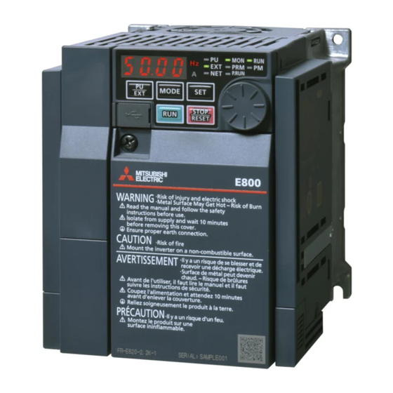
- Page 1 INVERTER FR-E800 Instruction Manual (Maintenance) Compact, high functionality inverters FR-E820-0008(0.1K) to 0330(7.5K) FR-E840-0016(0.4K) to 0170(7.5K) FR-E860-0017(0.75K) to 0120(7.5K) FR-E820-0008(0.1K) to 0330(7.5K)-E FR-E840-0016(0.4K) to 0170(7.5K)-E FR-E860-0017(0.75K) to 0120(7.5K)-E...
-
Page 2: Table Of Contents
Chapter 1 Introduction........5 Product checking ............7 About the related manuals . - Page 3 3.2.8 Insulation resistance test using megger ............. . . 52 3.2.9 Withstand voltage test.
-
Page 5: Chapter 1 Introduction
CHAPTER 1 Introduction Product checking ..............................7 About the related manuals............................9... - Page 6 Always read the instructions before use. Abbreviations Item Description Operation panel Inverter Mitsubishi Electric inverter FR-E800 series Parameter number (Number assigned to function) PU operation Operation using the PU (operation panel) External operation Operation using the control circuit signals...
- Page 7 • Other company and product names herein are the trademarks and registered trademarks of their respective owners. Notes on descriptions in this Instruction Manual • Connection diagrams in this Instruction Manual appear with the control logic of the input terminals as sink logic, unless otherwise specified.
-
Page 8: Product Checking
Product checking Inverter model FR-E8 0- Rating plate Inverter model MODEL :FR-E820-0008-1 Input rating INPUT :XXXXX OUTPUT:XXXXX Output rating SERIAL SERIAL:XXXXXXXXXXX Country of origin MADE IN XXXXX • A: The voltage class is shown. Symbol Voltage class 200 V class 400 V class 575 V class •... - Page 9 • E: Availability of circuit board coating / plated conductors is shown. Symbol Circuit board coating Plated conductors None Without coating Without plated conductors With coating Without plated conductors With coating With plated conductors Conforming to IEC 60721-3-3 3C2 NOTE •...
-
Page 10: About The Related Manuals
About the related manuals The manuals related to FR-E800 are as follows. Manual name Manual number FR-E800 Inverter Safety Guideline IB-0600857ENG FR-E800-E Inverter Safety Guideline IB-0600860ENG FR-E860 Inverter Safety Guideline IB-0600862ENG FR-E860-E Inverter Safety Guideline IB-0600863ENG FR-E800 Instruction Manual (Connection) IB-0600865ENG FR-E860 Instruction Manual (Connection) IB-0600906ENG... - Page 11 CHAPTER 2 Protective Functions Inverter fault and alarm indications.........................11 Reset method for the protective functions ......................12 Check and clear of the fault history ........................13 List of fault displays ..............................15 Causes and corrective actions..........................17 Check first when you have a trouble........................32...
-
Page 12: Chapter 2 Protective Functions
Protective Functions This chapter explains the "PROTECTIVE FUNCTIONS" that operate in this product. Always read the instructions before use. Inverter fault and alarm indications • When the inverter detects a fault, depending on the nature of the fault, the operation panel displays an error message or warning, or a protective function is activated to shut off the inverter output. -
Page 13: Reset Method For The Protective Functions
Reset method for the protective functions Reset the inverter by performing any of the following operations. Note that the accumulated heat value of the electronic thermal relay function and the number of retries are cleared (erased) by resetting the inverter. The inverter recovers about 1 second after the reset is released. -
Page 14: Check And Clear Of The Fault History
Check and clear of the fault history The operation panel stores the fault indications which appear when a protective function is activated to display the fault record for the past 10 faults. (Fault history) Check for the fault history Monitor mode Parameter setting mode Fault history mode... - Page 15 Operating procedure Turning ON the power of the inverter The operation panel is in the monitor mode. Selecting the parameter setting mode Press the MODE key to choose the parameter setting mode. (The parameter number read previously appears.) Selecting the parameter Turn the setting dial or press the UP/DOWN key until "ER.CL"...
-
Page 16: List Of Fault Displays
List of fault displays If the displayed message does not correspond to any of the Operation panel Data Refer Name indication code to page following or if you have any other problem, contact your sales representative. Undervoltage — Error message ... - Page 17 Operation panel Data Refer Operation panel Data Refer Name Name indication code to page indication code to page E.LF Output phase loss (H81) (HF5) External thermal E.OHT CPU fault relay operation (H90) (HF6) E.OPT Option fault (HA0) (HF7) Communication E.OP1 E.10 Output side fault option fault...
-
Page 18: Causes And Corrective Actions
Causes and corrective actions Error message A message regarding operational troubles is displayed. Output is not shut off. Operation panel lock Operation panel HOLD indication Description Operation lock is set. Operation other than pressing the STOP/RESET key is disabled. Check point -------------- Corrective action... - Page 19 Error Operation panel Err. indication • The RES signal is turned ON. Description • This error may occur when the voltage at the input side of the inverter drops. Corrective action • Turn OFF the RES signal. Warning Output is not shut off when a protective function is activated.
- Page 20 Regenerative brake pre-alarm Operation panel indication Appears if the regenerative brake duty reaches or exceeds 85% of the Pr.70 Special regenerative brake duty Description value. If the regenerative brake duty reaches 100%, a regenerative overvoltage (E. OV[ ]) occurs. •...
- Page 21 Maintenance timer Operation panel indication Appears when the inverter's cumulative energization time reaches or exceeds the parameter set value. Set the Description time until the MT is displayed using Pr.504 Maintenance timer 1 warning output set time (MT1). "MT" does not appear when the setting of Pr.504 is the initial value ("9999").
- Page 22 Incorrect parameter setting Operation panel indication Appears when the combination of setting values of Pr.451 and Pr.800 is incorrect, and the inverter output is shut Description off. Check point Check that the combination of the control method and the control mode is correct. Corrective action Set the control method and the control mode (Pr.451 and Pr.800) correctly.
- Page 23 Overcurrent trip during acceleration Operation panel E.OC1 indication When the inverter output current reaches or exceeds approximately 230% of the rated current during Description acceleration, the protection circuit is activated and the inverter output is shut off. • Check for sudden speed acceleration. •...
- Page 24 Overcurrent trip during deceleration or stop Operation panel E.OC3 indication When the inverter output current reaches or exceeds approximately 230% of the rated current during Description deceleration (other than acceleration or constant speed), the protection circuit is activated and the inverter output is shut off.
- Page 25 Regenerative overvoltage trip during deceleration or stop Operation panel E.OV3 indication If regenerative power causes the inverter's internal main circuit DC voltage to reach or exceed the specified Description value, the protection circuit is activated to stop the inverter output. The circuit may also be activated by a surge voltage produced in the power supply system.
- Page 26 Undervoltage Operation panel E.UVT indication When a PM motor is used, the protective function is activated in the following case: a fault such as power failure Description or voltage drop occurs, the converter voltage drops to cause the motor to coast, and restarting and coasting are repeated by the automatic restart after instantaneous power failure function.
- Page 27 Upper limit fault detection Operation panel E.LUP indication The inverter output is shut off when the load exceeds the upper limit fault detection range. This protective function Description is not available in the initial setting of Pr.1490 (Pr.1490 = "9999"). •...
- Page 28 Option fault Operation panel E.OPT indication • Appears when torque command by the plug-in option is selected using Pr.804 Torque command source selection and no plug-in option is mounted. This function is available under torque control. Description • Appears when the switch for manufacturer setting of the plug-in option is changed. •...
- Page 29 Retry count excess Operation panel E.RET indication The inverter output is shut off if the operation cannot be resumed properly within the number of retries set in Pr.67 Description Number of retries at fault occurrence. This function is available when Pr.67 is set. This protective function is not available in the initial setting (Pr.67 = "0").
- Page 30 Analog input fault Operation panel E.AIE indication The inverter output is shut off when a 30 mA or higher current or a 7.5 V or higher voltage is input to terminal 2 Description while the current input is selected by Pr.73 Analog input selection, or to terminal 4 while the current input is selected by Pr.267 Terminal 4 input selection.
- Page 31 Brake sequence fault Operation panel E.MB4 to 7 indication The inverter output is shut off when a sequence error occurs during use of the brake sequence function (Pr.278 Description to Pr.283). This protective function is not available in the initial status. (The brake sequence function is invalid.) Check point Find the cause of the fault occurrence.
- Page 32 PID signal fault Operation panel E.PID indication The inverter output is shut off if the measured value exceeds the PID upper limit or PID lower limit parameter setting, or the absolute deviation value exceeds the PID deviation parameter setting during PID control. Set this Description function in Pr.131 PID upper limit, Pr.132 PID lower limit, Pr.553 PID deviation limit and Pr.554 PID signal operation selection.
-
Page 33: Check First When You Have A Trouble
Check first when you have a trouble For Real sensorless vector control, also refer to the troubleshooting on speed control and torque control in the FR-E800 Instruction Manual (Function). • If the cause is still unknown after every check, it is recommended to initialize the parameters, set the required parameter values and check again. - Page 34 Check Possible cause Countermeasure point Check the connection. Two-wire or three-wire type connection is Use the Start self-holding selection (STP (STOP)) signal when the three-wire type incorrect. is used. Under V/F control, Pr.0 Torque boost Increase the Pr.0 setting by 0.5% increments while observing the rotation of a motor. setting is not appropriate.
-
Page 35: Motor Or Machine Is Making Abnormal Acoustic Noise
2.6.2 Motor or machine is making abnormal acoustic noise Check Possible cause Countermeasure point Input Take countermeasures against EMI. Disturbance due to EMI when the signal frequency or torque command is given Parameter Increase the Pr.74 Input filter time constant setting if steady operation cannot be through analog input terminal 2 or 4. -
Page 36: Motor Rotates In The Opposite Direction
2.6.5 Motor rotates in the opposite direction Check Possible cause Countermeasure point Main The phase sequence of output terminals U, V Connect the output side terminals (terminals U, V, and W) correctly. circuit and W is incorrect. The start signals (STF and STR signals) are Check the connection. -
Page 37: Speed Varies During Operation
2.6.8 Speed varies during operation Under Advanced magnetic flux vector control or Real sensorless vector control, the output frequency varies between 0 and 2 Hz as the load fluctuates. This is a normal operation and not a fault. Check Possible cause Countermeasure point Load... -
Page 38: Operation Panel Display Is Not Operating
2.6.10 Operation panel display is not operating. Check Possible cause Countermeasure point Main circuit, The power is not input. Input the power. control circuit The operation panel is not properly Front cover Check if the inverter front cover is installed securely. connected to the inverter. -
Page 39: Speed Does Not Accelerate
2.6.12 Speed does not accelerate Check Possible cause Countermeasure point The start command or frequency Check if the start command and the frequency command are correct. command is chattering. The wiring length is too long for the Input analog frequency command, causing a Perform the bias and gain calibration for the analog input. -
Page 40: Unable To Establish Ethernet Communication
2.6.14 Unable to establish Ethernet communication Check Possible cause Countermeasure point Check that the Ethernet cable is connected to the Ethernet connector properly and The Ethernet cable has a break. the Ethernet cable is not damaged. When excessive noise occurs around the inverter, change the communication Excessive electrical noise is present setting of the master. - Page 41 CHAPTER 3 Precautions for Maintenance and Inspection Inspection item................................41 Measurement of main circuit voltages, currents, and powers.................49...
-
Page 42: Chapter 3 Precautions For Maintenance And Inspection
Precautions for Maintenance and Inspection This chapter explains the precautions for maintenance and inspection of this product. Always read the instructions before use. Inspection item The inverter is a static unit mainly consisting of semiconductor devices. Daily inspection must be performed to prevent any fault from occurring due to the adverse effects of the operating environment, such as temperature, humidity, dust, dirt and vibration, changes in the parts with time, service life, and other factors. -
Page 43: Daily And Periodic Inspection
3.1.3 Daily and periodic inspection Inspection Corrective action Area of Inspection Check by interval Description at fault inspection item user occurrence Daily Periodic Surrounding Check the surrounding air temperature, humidity, dirt, Improve the ○ environment corrosive gas, oil mist, etc. environment. -
Page 44: Checking The Inverter And Converter Modules
Inspection Corrective action Area of Inspection Check by interval Description at fault inspection item user occurrence Daily Periodic Contact the • Check that indications are correct. ○ manufacturer. Indication • Check for stains. ○ Clean. Display Stop the equipment and Meter/counter Check that readouts are correct. -
Page 45: Cleaning
Converter module Inverter module R/L1 S/L2 T/L3 N/− 3.1.5 Cleaning Always run the inverter in a clean status. When cleaning the inverter, gently wipe dirty areas with a soft cloth immersed in neutral detergent or ethanol. NOTE • Do not use solvent, such as acetone, benzene, toluene and alcohol, as these will cause the inverter surface paint to peel off. •... - Page 46 NOTE • Refer to the FR-E800 Instruction Manual (Function) to perform the life check of the inverter parts. Replacement procedure of the cooling fan The replacement interval of the cooling fan used for cooling the parts generating heat such as the main circuit semiconductor is greatly affected by the surrounding air temperature.
- Page 47 Connect the fan connectors. FR-E820-0080(1.5K) to 0330(7.5K) FR-E840-0040(1.5K) to 0170(7.5K) FR-E860-0027(1.5K) to 0120(7.5K) Install the fan cover. 2. Insert hooks until you hear 1. Insert hooks into a click sound holes. FR-E820-0080(1.5K) to 0330(7.5K) FR-E840-0040(1.5K) to 0170(7.5K) FR-E860-0027(1.5K) to 0120(7.5K) NOTE •...
-
Page 48: Inverter Replacement
• The control terminal block must be replaced in case of failure of the relay connected to the relay output terminals A, B, and C. (Refer to page 47.) (After replacing the control terminal block, set the switch to the correct position in accordance with the control logic of input signals.) (Refer to the FR-E800 Instruction Manual (Connection) or FR-E860 Instruction Manual (Connection).) 3.1.7... - Page 49 • Check that the terminal block is parallel to the inverter and the pins on the inverter control circuit connector are not bent. After checking proper connection, tighten the screw to fix the terminal block. Control circuit terminal block Inverter's control circuit connector Control circuit terminal block...
-
Page 50: Measurement Of Main Circuit Voltages, Currents, And Powers
Measurement of main circuit voltages, currents, and powers Since the voltages and currents on the inverter power supply and output sides include harmonics, measurement data depends on the instruments used and circuits measured. When instruments for commercial frequency are used for measurement, measure the following circuits with the instruments given on the next page. -
Page 51: Measurement Of Powers
Measuring points and instruments Item Measuring point Measuring instrument Remarks (reference measured value) Commercial power Between R/L1 and S/L2, Input voltage Within permissible AC voltage fluctuation. (Refer to S/L2 and T/L3, and T/L3 the FR-E800 Instruction Manual (Connection) or and R/L1 FR-E860 Instruction Manual (Connection).) Input current... -
Page 52: Measurement Of Voltages And Use Of Pt
3.2.2 Measurement of voltages and use of PT Inverter input side Use a digital power meter (for inverter) on the inverter's input side. Inverter output side When using a measuring instrument, use a digital power meter for inverters as the inverter outputs PWM-controlled square wave voltage. - Page 53 3.2.8 Insulation resistance test using megger • For the inverter, conduct the insulation resistance test on the main circuit only as follows and do not perform the test on the control circuit. (Use a 500 VDC megger.) NOTE • Before performing the insulation resistance test on the external circuit, disconnect the cables from all terminals of the inverter so that the test voltage is not applied to the inverter.
- Page 54 MEMO 3. Precautions for Maintenance and Inspection 3.2 Measurement of main circuit voltages, currents, and powers...
- Page 55 Revisions *The manual number is given on the bottom left of the back cover. Revision date Manual number Revision Dec. 2019 IB(NA)-0600874ENG-A First edition IB-0600874ENG-A...
- Page 56 HEAD OFFICE: TOKYO BUILDING 2-7-3, MARUNOUCHI, CHIYODA-KU, TOKYO 100-8310, JAPAN IB(NA)-0600874ENG-A(1912)MEE Printed in Japan Specifications subject to change without notice.