
Related Manuals for Secure APEX 100


Summary of Contents for Secure APEX 100
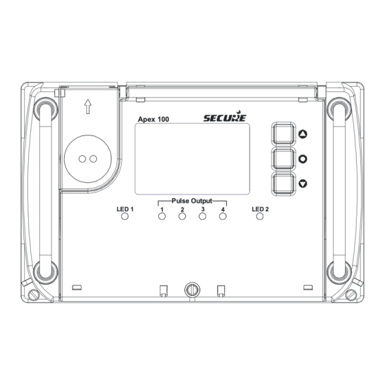
- Page 1 APEX 100 Rack Meter User Manual BGX501-742-R01 Apex 100 Pulse Output LED 1 LED 2...
- Page 2 Copyright © 2010-2011, Secure International Holdings Pte. Ltd. All rights reserved. E&OE. Apex® is a registered trade name of Secure Meters Ltd. Other product names are trademarks or registered trademarks of their respective owners. Page 2 of 104 BGX501-742-R01, APEX100 User Manual...
-
Page 3: Table Of Contents
Rear Sealing Arrangement ......................15 2.2.2 Pulse I/O ............................16 Apex 100 Product Dimensions ........................18 Rack Mounting Enclosures .......................... 19 Apex 100 with 11” Rack Mounting Diagrams and Dimensions ............ 20 2.4.1 Apex 100 and M-Cubed BCS ....................22 Configuration ............................... 22 3.1.1 Creating a new tariff ........................ - Page 4 Time of Use (TOU) ............................72 5.3.1 Day Type ............................72 5.3.2 Seasons ............................72 5.3.3 Special Day ........................... 72 5.3.4 Rate Registers ..........................72 5.3.5 Maximum Demand Registers ....................... 72 5.3.6 Triggers for Maximum Demand ....................73 5.3.7 Universal Maximum Demand Registers ..................73 5.3.8 Cumulative Maximum Demand Registers ..................
- Page 5 PICS BGX501-742-R01, APEX 100 User Manual Page 5 of 104...
-
Page 6: Introduction
1 Introduction 1.1 System Overview The Apex 100 Rack is a multi-functional, electronic, electricity energy meter used for grid metering. It provides high accuracy in measuring electrical and also in measuring instantaneous quantities such as current, voltage, power, frequency etc. The Apex 100 offers extensive configurable functional features together with the high accuracy enable application areas more numerous than for traditional electricity meters. -
Page 7: Overview Of Possible Hardware Options In Apex 100
1.1.1 Overview of possible hardware options in Apex 100 19" Rack 11" Rack Meter Meter Meter Meters Self Powered Variant Variant Power Supply (1) Power Supply (1) Not required APS (48-276 AC/DC) Self powered Power Supply (2) Power Supply (2) -
Page 8: About This User Manual
It also explains the different variants and mounting arrangements. 1.3 Important safety information Care must be exercised during the installation of the Apex 100 meter and associated equipment due to the presence of mains voltages. Various points under the terminal cover and on the main printed circuit board (PCB) under the main cover operate at hazardous voltages. -
Page 9: Rack Mounted Product Description
MD button. The battery compartment and USB port are optional features. The cover is secured in position by a retaining screw and sealed. PICS BGX501-742-R01, APEX 100 User Manual Page 9 of 104... - Page 10 Figure 5: Front Cover Opened The 1107 optical port cover can be slid upwards in the arrow direction to the open position. The cover has a captive design and cannot be removed and lost. There is an optional sealing point (see Figure 6). Sealing Points Cover Closed Cover Open...
-
Page 11: Front Cover Sealing
MD pushbutton and internal areas. There are also sealing points on either side of the meter for securing it to a rack or frame. The sealing bore diameter is 2.0 mm and is suitable for Ferrule, NIC & SAFCON type seals. PICS BGX501-742-R01, APEX 100 User Manual Page 11 of 104... -
Page 12: Battery Compartment
2.1.3 Replacing the Meter Reading Battery The meter reading battery is fitted on the self power supply variant of the Apex 100. The meter reading battery enables a user to take a reading and view the display in the absence of a power supply. Replacing the battery is an easy task, refer to the figures above and follow these instructions carefully. -
Page 13: Rear Details Of Meter
Figure 9: Rear view showing connectors Figure 10: Rear Isometric View Rear Connections The Apex 100 uses standard Essailec connectors with the following connections: Connector for current & voltage terminals (6+4 pins) Pulse i/o pins (Table shows the five possible variants) Auxiliary pins (4 terminals for AC supply &... - Page 14 Pulse Inputs Pulse Configurable Variant Outputs *Pulse I/O Status Counter * I/O information will be handled by the I/O type Variant 1 is the default Variants 2-5 are available on request Table 1: Pulse I/O Variants The diagram shows the rear connector with its pinning diagram for Variant A (not fully loaded). RS232 RS485 IN 04 03 02 01...
-
Page 15: Rear Sealing Arrangement
When the meter is fitted into the rack, a cover can be fitted which conceals all the rear connectors. The figures below show the sealing points for the rear cover. The figures show single and double rack examples with an enlarged detailed view of a sealing point (A). PICS BGX501-742-R01, APEX 100 User Manual Page 15 of 104... -
Page 16: Pulse I/O
DETAIL “A” Enlarged View of Sealing Points Figure 13: Rear Sealing Points – Single Rack Example Rear Cover Sealing Points Figure 14: Rear Sealing Points – 19” Rack, Two Meter Example 2.2.2 Pulse I/O I/O Pulses (12) 4 Fixed Pulse 4 Fixed Pulse 4 Configurable Outputs... - Page 17 Any one of the status type pulse inputs can be used for a time synch pulse. Status and Counter information shall is available in display and Modbus. Note: The Input Counter and Status are both available on Modbus. PICS BGX501-742-R01, APEX 100 User Manual Page 17 of 104...
-
Page 18: Apex 100 Product Dimensions
2.3 Apex 100 Product Dimensions This section describes and illustrates the key product dimensions for the Apex 100 rack meter. nominal dimensions in mm Figure 17: Rack Model Dimensions Page 18 of 104 BGX501-742-R01, APEX100 User Manual PICS... -
Page 19: Rack Mounting Enclosures
RJ45 connector are connected and removed manually. Figure 18: Single Meter Enclosure Figure 19: Double Enclosure The Apex 100 is compatible with single 11” or double 19” standard rack installations. PICS BGX501-742-R01, APEX 100 User Manual... -
Page 20: Apex 100 With 11" Rack Mounting Diagrams And Dimensions
2.4.1 Apex 100 with 11” Rack Mounting Diagrams and Dimensions The following diagrams show dimensional and sealing points for the Apex 100 when used with the 11” rack 279.60 261.80 50.30 293.30 376.25 Figure 20: Front and Side View Page 20 of 104... - Page 21 Sealing screw Sealing screw sealing (2 locations.) (2 locations) The following diagrams shows the Apex 100 Rack mounted with panel cut out details. Figure 21: Panel cut out details PICS BGX501-742-R01, APEX 100 User Manual Page 21 of 104...
-
Page 22: Apex 100 And M-Cubed Bcs
3 Apex 100 and M-Cubed BCS This section describes the various operations that can be performed using the M-Cubed BCS with APEX 100 Meter. M-Cubed Apex 100 Meter Figure 22: Apex100 and M-Cubed BCS M-Cubed stands for Modular Meter Management and is the name of Secure‟s software suite for programming meters, reading data and reporting from energy meters. -
Page 23: Get A Current Tariff
When complete, save the configurations in a file. The configurations will be uploaded to the meter. Offline Mode (Tariff file preparation for later use) Select the Mask Family “E300 APEX 100” Select appropriate Version Number Select CLEM Name as “MJ10xxxx”. -
Page 24: Modifying A Current Tariff
Select Get configuration. Select either SML or DLMS mode. M-Cubed will now attempt to communicate with the meter. If the meter is not connected or is switched off then a warning screen will be displayed. The current configuration from the meter will now be downloaded. A warning screen will be displayed if the meter type is not supported. -
Page 25: Commissioning The Apex Meter
Communication will now commence. If the meter is not connected then a warning screen will be displayed. The meter data will now be downloaded and the data will be saved in a CDF file at a predefined location. PICS BGX501-742-R01, APEX 100 User Manual Page 25 of 104... -
Page 26: Using The Display
4 Using the Display There are two types of display: Auto Scroll and Manual Mode. The two types of display and their associated settings and parameters are discussed in this section. All single parameters, e.g. voltage, will be displayed with their OBIS codes. -
Page 27: Display Groups
The meter has four user buttons. One button is for MD reset and is behind a sealable door. The other three are used for navigating through the display and configuration menu options. PICS BGX501-742-R01, APEX 100 User Manual Page 27 of 104... -
Page 28: Menu Example Screens
Menu User Apex 100 Controls Pulse Output LED 2 LED 1 MD Reset Button Figure 25: User Buttons A page can be selected by pressing the enter button. A navigation screen will appear showing all the available pages. The Up and Down buttons can then be used to choose a page. Press the Enter button to select your choice. - Page 29 Meter Serial Number Secondary Voltage Primary Voltage Secondary Current Meter Type Primary Current (HT 3P4W or HT 3P3W Figure 27: Fixed Display Page PICS BGX501-742-R01, APEX 100 User Manual Page 29 of 104...
- Page 30 Meter constants for metrological LED1 and LED2 Meter Date and Time Instantaneous Cumulative Energy Register Act I (T) Active Import Total Act E (T) Apparent Import Total App I Apparent Export App E Instantaneous Power and Frequency Active (T) Active Total and Active (F) Active Fundamental Reactive Frequency (Hz)
- Page 31 Channel 0 = Optical port Channel 1 = RS-485 port Channel 3 = Ethernet port Channel 4 = Ethernet port Meter health condition about the real time clock (RTC) and meter memory PICS BGX501-742-R01, APEX 100 User Manual Page 31 of 104...
- Page 32 Up to seven user configurable pages can be defined complete with page title e.g. PAGE-1 METER INFO, see Figure 28Figure 27 below. Apex 100 F i x e d Di s p l a y P a g e P A GE - 1 ME T E R I NF O...
- Page 33 PICS BGX501-742-R01, APEX 100 User Manual Page 33 of 104...
- Page 34 Use the Up/Down buttons to scroll to the required page. The selection will be highlighted. Press the Enter button to open the page. Use the Up/Down buttons to scroll within the page and view the attributes. When finished scroll back to this screen and choose Exit. The title shows that we are in page-1 Meter Info.
- Page 35 Meter secondary current (as per scaling) The replaceable battery status The CT ratio as per primary/secondary current. For this example 500/5 = 100 The Local Area Network (LAN) status. Connected or Not connected PICS BGX501-742-R01, APEX 100 User Manual Page 35 of 104...
- Page 36 To select page-2 you need to cycle through the screens until you get to the page selection screen menu, press Enter to use this screen. Scroll down to your choice, for this example we will go to Page-2. Press Enter to view page-2. Phase sequence of R,Y and B phases.
- Page 37 The instantaneous B phase voltage 6.24kV Instantaneous % average voltage of V nominal 102% Instantaneous line voltage R-Y 11.45kV Instantaneous line voltage Y-B 10.603 kV Instantaneous line voltage B-R 11.643kV PICS BGX501-742-R01, APEX 100 User Manual Page 37 of 104...
- Page 38 Instantaneous phase angle between R and Y voltage The R-Y voltage angle in degrees A12 = 90° (degrees) Instantaneous phase angle between Y & B voltage A23 = 120° Instantaneous phase angle between B & R voltage A31 = 149° Instantaneous active current R-phase i1 = 42.9 A Instantaneous active current Y-phase...
- Page 39 Instantaneous reactive current R-phase I1 = 1.2 A Instantaneous reactive current Y-phase i2 = 0.8 A Instantaneous reactive current B-phase i3 = 1.2 A Instantaneous line current R-phase L1 = 42.9 A PICS BGX501-742-R01, APEX 100 User Manual Page 39 of 104...
- Page 40 Instantaneous line current Y-phase L2 = 41.6 A Instantaneous line current B-phase L3 = 42.9 A Instantaneous angle between voltage and current of R-phase in degrees. A11 = 11° Instantaneous angle between voltage and current of Y-phase in degrees. A22 = 1° Instantaneous angle between voltage and current of B-phase in degrees.
- Page 41 Instantaneous active fundamental power 0.82 MW or 820 kW Instantaneous reactive power 0.02 MVAr or 20 kVAr Instantaneous apparent power 0.82 MVA or 820 kVA Instantaneous three-phase average power factor 0.999 Lag PICS BGX501-742-R01, APEX 100 User Manual Page 41 of 104...
- Page 42 Instantaneous R-phase average power factor 0.999 Lag Instantaneous Y-phase average power factor 0.999 Lag Instantaneous B-phase average power factor 0.999 Lag Page-3 Page-3 has been configured to view the energy registers. Page 42 of 104 BGX501-742-R01, APEX100 User Manual PICS...
- Page 43 Main Energy Register for the total active energy imported in megawatt hours (MWh). The example shows: 49.06 MWh Main Energy Register for the fundamental active energy imported in megawatt hours (MWh). The example shows: 49.09 MWh PICS BGX501-742-R01, APEX 100 User Manual Page 43 of 104...
- Page 44 Main Energy Register for the fundamental active energy exported in megawatt hours (MWh). The example shows: 00.00 MWh, indicating that no energy was exported. Main Energy Register for reactive energy (Q1) imported in megavolt ampere reactive hours (MVArh). The example shows: 0.89 MVArh Main Energy Register for reactive energy (Q2) imported in megavolt ampere reactive hours (MVArh).
- Page 45 The example shows that no reactive energy was imported. Main Energy Register for reactive energy (Low) exported in megavolt ampere reactive hours (MVArh). The example shows that no reactive energy was imported. PICS BGX501-742-R01, APEX 100 User Manual Page 45 of 104...
- Page 46 Main Energy Register for reactive energy (Q1+Q2) imported in megavolt ampere reactive hours (MVArh). The example shows that 0.89 MVArh of reactive energy was imported. Main Energy Register for reactive energy (Q3+Q4) exported in megavolt ampere reactive hours (MVArh). The example shows that 0.13 MVArh of reactive energy was exported . Main Energy Register for Net Active energy (I-E) in megawatt hours (MWh).
- Page 47 (MWh). The example reading is 49.13560 MWh. High resolution energy register for fundamental active export displayed in megawatt hours (MWh). The example reading shows that no energy was registered. PICS BGX501-742-R01, APEX 100 User Manual Page 47 of 104...
- Page 48 High resolution energy register for reactive import (Q1) displayed in megavolt ampere reactive hours (MVArh). The example reading shows that 0.89628 MVArh was registered. High resolution energy register for reactive import (Q2) displayed in megavolt ampere reactive hours (MVArh). The example reading shows that no energy was registered. High resolution energy register for reactive export (Q3) displayed in megavolt ampere reactive hours (MVArh).
- Page 49 The example reading shows that 0.89988 MVArh energy was imported. High resolution energy register for reactive export (Q3+Q4) displayed in megavolt ampere hours (MVArh). The example reading shows that 0.13071 MVArh energy was exported. PICS BGX501-742-R01, APEX 100 User Manual Page 49 of 104...
- Page 50 High resolution energy register for net active (I-E) displayed in megawatt hours (MWh). The example reading shows that 49.27711 MWh energy was registered. High resolution energy register for net reactive high (I-E) displayed in megawatt hours (MVArh). The example reading shows that 0.74329 MVArh energy was registered.
- Page 51 00:00 Hrs (midnight). Up to three histories are available. The screen shows daily history snap-1 The screen shows daily history snap-2 This and the following screens are daily snap history-3. PICS BGX501-742-R01, APEX 100 User Manual Page 51 of 104...
- Page 52 Page 52 of 104 BGX501-742-R01, APEX100 User Manual PICS...
- Page 53 PICS BGX501-742-R01, APEX 100 User Manual Page 53 of 104...
- Page 54 Page-5 Tamper Status Page-5 details tamper events and status. Events are discussed in section 4.7 Page 54 of 104 BGX501-742-R01, APEX100 User Manual PICS...
- Page 55 This screen will display if R-phase CT reversal has been detected. This screen will display if Y-phase CT reversal has been detected. This screen will be displayed If no voltage related event has been detected. PICS BGX501-742-R01, APEX 100 User Manual Page 55 of 104...
- Page 56 This screen will display if an R-phase PT missing event has been detected. This screen will display if a B-phase PT missing event has been detected. This screen will display if a voltage related event has been detected. The display indicates a low voltage event has occurred.
- Page 57 This screen shows the time of the last occurred event. This screen shows the date of the last occurred event. This screen shows the time of the last restored event. PICS BGX501-742-R01, APEX 100 User Manual Page 57 of 104...
- Page 58 This screen shows the date of the last restored event. Page-6 Last SIP Data Load survey and Survey Integration Period SIP are discussed in section 5.4. These screens allow you to view the previous SIP data from the load survey. Page 58 of 104 BGX501-742-R01, APEX100 User Manual PICS...
- Page 59 When finished scroll back to this screen and choose Exit (scroll to the bottom of screen). The following screens show detail from the last SIP data. Scroll through the screens to view the data. PICS BGX501-742-R01, APEX 100 User Manual Page 59 of 104...
- Page 60 Page 60 of 104 BGX501-742-R01, APEX100 User Manual PICS...
- Page 61 PICS BGX501-742-R01, APEX 100 User Manual Page 61 of 104...
- Page 62 Page-7 Miscellaneous Use the Up/Down buttons to scroll to page-7 Miscellaneous. The selection will be highlighted. Press the Enter button to open the page. Use the Up/Down buttons to scroll within the page and view the various screens. When finished scroll back to this screen and choose Exit (scroll to the bottom of screen).
- Page 63 PICS BGX501-742-R01, APEX 100 User Manual Page 63 of 104...
- Page 64 Favourite Page This page is used for your selection of display parameters. press and hold Down for 5 seconds Down To add a parameter, go to the page containing the parameter that you require. Once the required field is selected press the down key for 5 seconds, the selected parameter will now be added to your favourite page. To delete a parameter from your favourite page, go to your favourite page and select the parameter you wish to delete and press the down key for 5 sec.
- Page 65 Figure 29: Front view showing metrological LEDs The configuration pages are used to set-up and enable features such as the metrological LEDs, the display timeout and manage your favourite selections. The displays are shown below. PICS BGX501-742-R01, APEX 100 User Manual Page 65 of 104...
- Page 66 Use the Up/Down buttons to scroll to the Configuration page. The selection will be highlighted. Press the Enter button to open the page. Use the Up/Down buttons to scroll within the page and view the various screens. When finished scroll back to this screen and choose Exit (scroll to the bottom of screen).
- Page 67 Metro LED2 selected Select either Reactive Energy or Apparent Energy. Reactive Energy selected for Metro LED2 Confirmation screen will be displayed This screen allows you to set the display timeout settings. PICS BGX501-742-R01, APEX 100 User Manual Page 67 of 104...
-
Page 68: Events
4.7 Events The Apex 100 has a number of defined events and alarms that are stored in the meter‟s event log when they occur. The events are arranged into eight compartments with an overall maximum of 250 events. An event is displayed with a description, a time stamp and an OBIS code. - Page 69 Phase wise current circuit reversal CT Miss Current unbalance Power on/off Feeder Supply Fail Magnet Interference There is a delay between detection and restoration points to guard against erroneous or faulty detection. PICS BGX501-742-R01, APEX 100 User Manual Page 69 of 104...
-
Page 70: Metering
5 Metering 5.1 Quadrant Metering The Apex 100 conforms to IEC 62053-23 for quadrants see Figure 30Figure Figure 30: Quadrant Metering 5.2 Energy Registers The Energy Channel Registers with their availability are shown in the table below. Availability for Daily... - Page 71 Active Import Total (Q1+Q4) - Phase 3 Active Export Total (Q2+Q3) - Phase 1 Active Export Total (Q2+Q3) - Phase 2 Active Export Total (Q2+Q3) - Phase 3 Table 411: Energy Channel Registers PICS BGX501-742-R01, APEX 100 User Manual Page 71 of 104...
-
Page 72: Time Of Use (Tou)
Y – Available for selection N – Not available D – Default (Based on Indian companion standard) & should not be changed Notes: Rate & MD registers are not available for category B meters In Display any parameter can be selected. All the bi-directional energy registers (* marked) use a sign indication („-„sign will be available for negative value and no sign for positive value). -
Page 73: Triggers For Maximum Demand
5.3.9 Load Survey (Loggers) Apex 100 has two parallel and individually configurable loggers. The following description covers both loggers. Load profiling of energy and instantaneous parameters can be selected through the configuration and can be changed at run time by downloading a new configuration into the meter. - Page 74 SSP „00 min‟ means fixed block type survey computation. A maximum of 12 parameters can be selected. Please note that all previous load survey data will be lost when a new load survey configuration is loaded, so be sure to read the data before commencing a new configuration. Number of Parameters Note 1: Maximum number of load survey days can be limited at factory end.
- Page 75 Voltage Phase Angle - A31 Min/Max/Instant/Avg Instantaneous Voltage THD - Phase 1 Min/Max/Instant/Avg Instantaneous Voltage THD - Phase 2 Min/Max/Instant/Avg Instantaneous Voltage THD - Phase 3 Min/Max/Instant/Avg Instantaneous All Phase Voltage THD Min/Max/Instant/Avg PICS BGX501-742-R01, APEX 100 User Manual Page 75 of 104...
- Page 76 Instantaneous Current THD - Phase 1 Min/Max/Instant/Avg Instantaneous Current THD - Phase 2 Min/Max/Instant/Avg Instantaneous Current THD - Phase 3 Min/Max/Instant/Avg Instantaneous All Phase Current THD Min/Max/Instant/Avg Instantaneous Active Power - Phase 1 Min/Max/Instant/Avg Instantaneous Active Power - Phase 2 Min/Max/Instant/Avg Instantaneous Active Power - Phase 3...
-
Page 77: Demand Resets/Billing Actions/History
If no triggers are defined then it will act as a self-trigger where all the parameters will independently log their maximum demand. PICS BGX501-742-R01, APEX 100 User Manual Page 77 of 104... -
Page 78: Daily Energy Snapshots
5.3.11 Daily Energy Snapshots Apart from the above mentioned eight TOD MD registers, a separate register is available to record the maximum demand during the entire day (i.e. 00-24 hours) known as universal demand register. This is not configurable through tariff. 5.4 Load survey Load profiling of energy and instantaneous parameters are fixed at factory end, and these can‟t be changed at run time. -
Page 79: Daily Energy Snapshot
The configuration can then be modified using the CC Tool. The Apex 100 does not require to be switched off during the configuration mode and will only implement the new configuration when all the blocks have been received and authenticated... -
Page 80: Communication Ports
5.8 Meter Reading The Apex 100 uses DLMS, the new global protocol, for meter reading. This is the only protocol supported by the meter for meter reading. In DLMS protocol the BCS is considered the client and the meter is the server. On request by the BCS, the meter will send all its supported OBIS codes and expected queries. - Page 81 Signed Active Power – kW (+ import: - export) Instantaneous Signed Active Power – kW (+ import: - export) Instantaneous Cumulative Energy – kWh (Import) Energy Cumulative Energy – kWh (Export) Energy Cumulative Energy – kVAh(Import) Energy PICS BGX501-742-R01, APEX 100 User Manual Page 81 of 104...
- Page 82 Cumulative Energy – kVAh(Export) Energy Event Number of power-failures. Event Cumulative power-failure duration Event Cumulative Tamper Count Demand Cumulative Billing count Event Cumulative programming (DLMS transaction) count (as per Indian companion standard) Demand Date and Time of last MD Reset Section S.no Group...
- Page 83 Profile Event profile - Log3 Profile Event profile - Log4 Profile Event profile - Log5 Profile Event profile - Log6 Profile Event profile - Log7 Profile Scaler Profile - Event PICS BGX501-742-R01, APEX 100 User Manual Page 83 of 104...
- Page 84 Section S.no Group Parameter Real Time Clock – Date and Time Instantaneous R Phase Line Current – L Instantaneous Y Phase Line Current – L Instantaneous B Phase Line Current – L Instantaneous Voltage – V for 3 Ф / 4W Instantaneous Voltage –...
- Page 85 Demand Cumulative Billing count Event Cumulative programming (DLMS transaction) count (as per Indian companion standard) Demand Date and Time of last MD Reset PICS BGX501-742-R01, APEX 100 User Manual Page 85 of 104...
- Page 86 Section S.no Group Parameter Real Time Clock – Date and Time Instantaneous Energy Active Import (Q1+Q4) Energy Active Export (Q2+Q3) Reactive Import while Active Import – Q1 Energy Reactive Import while Active Export – Q2 Energy MidNight Reactive Export while Active Export – Q3 Energy Energies Reactive Export while Active Import –...
- Page 87 Power Factor – R phase Instantaneous Power Factor – Y phase Instantaneous Power Factor – B phase Instantaneous Cumulative Energy – Active Import Energy Cumulative Energy – Active Export Energy PICS BGX501-742-R01, APEX 100 User Manual Page 87 of 104...
-
Page 88: Profiles
Section S.no Group Parameter General Logical device name General Current Association System General Meter Reader Association General Utility Settings Association 5.9 Profiles Meter data is divided into logical data sets and then mapped onto DLMS profiles. The following profiles are defined and may be implemented as per requirement. -
Page 89: Selectivity For Profiles (Based On Dlms Indian Companion Standard)
Data can be selectively read from the meter. Starting with the latest entry, the number of previous entries can be read. The table below shows the profile with their granularity. PICS BGX501-742-R01, APEX 100 User Manual Page 89 of 104... -
Page 90: Security
5.9.5 USB The USB connector is provided in the Apex 100 for the collection of meter readings in a USB pen drive. Only a predefined profile will be accepted. The USB port will only detect pen drives; no other hardware, such as mass data storage cards, cameras or mobiles will be detected. - Page 91 At the Apex 100 meter, Select the USB option from the meter display menu using the keypad . Plug in the USB Pen drive to USB connector or first plug in the USB Pen drive in USB connector and select the USB option from display menu A meter reading will now be completed and saved on the USB pen drive.
-
Page 92: Meter Specification
6 Meter Specification This section details the meter specification. 6.1 Applicable standards and external certification The Apex 100 meter conforms to the following standards: IEC62052-11 & IEC62053-22 (Static meters for Active Energy Class 0.2S) IEC62053-23 IEC 62056-31 IS 14697 CBIP304 Harmonic standard and power quality analyzer - EN50160 and IEC61000-4-30 class A MID for class 0.5S variant... -
Page 93: Metrological Specification
Power Consumption in case of Aux Voltage circuit<0.5VA/phase supply (with communication module) Current circuit<0.5VA/phase Auxiliary APS<8VA Power consumption in case of Self Voltage circuit<6VA/phase power supply (with communication module) Current circuit<0.5VA/phase. PICS BGX501-742-R01, APEX 100 User Manual Page 93 of 104... -
Page 94: Emi/Emc Specification
6.3 EMI/EMC specification Radiated Emission CISPR 22 (Class A equipment) CISPR 22 (Class A equipment) Conducted emission Internal limits are 8 dB less than the CIPSR limits IEC 61000-4-2 Contact Direct type: +/- 8KV Contact Indirect type: +/- 8KV Air discharge: +/- 15 KV Electro static discharge Internal limits Contact Direct type: +/- 10KV... - Page 95 PICS BGX501-742-R01, APEX 100 User Manual Page 95 of 104...
- Page 96 Page 96 of 104 BGX501-742-R01, APEX100 User Manual PICS...
-
Page 97: Appendix A: Abbreviations
Bureau of Indian Standards CLEM: Application program for metering application DLMS: Device Language Mark up Specification ICS DLMS: Indian Companion Standard for Device Language Mark up Specification. SCADA: Supervisory Control and Acquisition PICS BGX501-742-R01, APEX 100 User Manual Page 97 of 104... -
Page 98: Appendix B: Material Declaration
Appendix B: Material Declaration The material declaration for the meter and rack are shown below: Enclosure Rack- Mild steel with Aluminium Meter- Mild steel overall Meter back plate- Mild steel Meter current and voltage terminals- Brass with gold and silver plating Handle –... -
Page 99: Appendix C: Communication Ports
The RS 232 standard communication port is used to connect the meter with other communication devices such as computers and modems through a serial cable. Description Pins 6-9 N/C Table 52: RS-232 D-type port description PICS BGX501-742-R01, APEX 100 User Manual Page 99 of 104... - Page 100 RS 485 Ports The RS-485 serial communication ports are intended to be used to connect the Apex 100 to a network for multi- drop communications. The RS-485 network is looped through the input connector to the output connector. Connector 2 x RJ45 RS-485 IN & OUT Data Rate 1200 to 115.2Kbps...
- Page 101 The connector wiring is standard Ethernet configuration and is shown below. RJ45 Female Port Name Description Transmit Data+ Transmit Data- Receive Data+ Not connected pin8 pin1 Not connected Receive Data- Not connected Not connected Table 96: RJ45 Ethernet Port Description PICS BGX501-742-R01, APEX 100 User Manual Page 101 of 104...
- Page 102 Table 118: USB Port Details The USB connector is provided in the Apex 100 for the collection of meter readings in a USB pen drive. Only a predefined profile will be accepted. The USB port will only detect pen drives; no other hardware, such as mass data storage cards, cameras or mobiles will be detected.
- Page 103 PICS BGX501-742-R01, APEX 100 User Manual Page 103 of 104...
- Page 104 +44 1962 841046 : + 91 294 2492300 Cewe Instrument AB +91 294 2492310 SE 611 20 Box 1006, Nyköping Secure Australia Pty Ltd Sweden 258 Darebin Road : +46 155 175 00 Fairfield VIC 3078 Australia +46 155 775 97...
Need help?
Do you have a question about the APEX 100 and is the answer not in the manual?
Questions and answers