Table of Contents
Advertisement
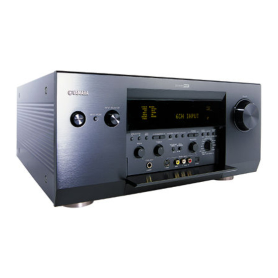
RX-Z1
AV Receiver
INPUT SELECTOR
INPUT MODE
STANDBY
/ON
SPEAKERS
6CH
PRESET
A
B
INPUT
PROGRAM
STEREO
FM/AM A/B/C/D/E
/TUNING
EFFECT
BASS
TREBLE
BALANCE
PROCESSOR
BASS
DIRECT
EXTENSION
ON
OFF
L
SILENT
VIDEO AUX
PHONES
S VIDEO
VIDEO
L
AUDIO
R
OWNER'S MANUAL
U
VOLUME
PRESET
TUNING
/TUNING
MEMORY
MODE
EDIT
MAN'L/AUTO FM
AUTO/MAN'L MONO
SOURCE/REMOTE
D–TV/LD
DVD
CABLE
MD/TAPE
SAT
CD–R
VCR 1
TUNER
VCR 2
CD
VCR 3/DVR
PHONO
R
VIDEO AUX
REC OUT/ZONE 2
OPTICAL
Advertisement
Chapters
Table of Contents
Troubleshooting

Related Manuals for Yamaha pmn


Summary of Contents for Yamaha pmn
- Page 1 RX-Z1 AV Receiver INPUT SELECTOR INPUT MODE STANDBY SPEAKERS PRESET PRESET TUNING INPUT PROGRAM STEREO FM/AM A/B/C/D/E /TUNING /TUNING MEMORY MODE EFFECT EDIT MAN'L/AUTO FM AUTO/MAN'L MONO BASS TREBLE BALANCE SOURCE/REMOTE D–TV/LD PROCESSOR BASS CABLE MD/TAPE DIRECT EXTENSION CD–R VCR 1 TUNER VCR 2 VCR 3/DVR...
-
Page 2: Important Safety Instructions
IMPORTANT SAFETY INSTRUCTIONS CAUTION RISK OF ELECTRIC SHOCK DO NOT OPEN CAUTION: TO REDUCE THE RISK OF ELECTRIC SHOCK, DO NOT REMOVE COVER (OR BACK). NO USER-SERVICEABLE PARTS INSIDE. REFER SERVICING TO QUALIFIED SERVICE PERSONNEL. • Explanation of Graphical Symbols The lightning flash with arrowhead symbol, within an equilateral triangle, is intended to alert you to the presence of uninsulated “dangerous voltage”... - Page 3 This product, when installed as indicated in the instructions contained in this manual, meets FCC requirements. Modifications not expressly approved by Yamaha may void your authority, granted by the FCC, to use the product. IMPORTANT : When connecting this product to accessories and/or another product use only high quality shielded cables.
- Page 4 12 Only voltage specified on this unit must be used. Using this unit with a higher voltage than specified is dangerous and may cause fire, damage to this unit, and/or personal injury. YAMAHA will not be held responsible for any damage resulting from use of this unit with a voltage other than specified.
- Page 5 This product, when installed as indicated in the instructions contained in this manual, meets FCC requirements. Modifications not expressly approved by Yamaha may void your authority, granted by the FCC, to use the product. IMPORTANT: When connecting this product to accessories and/or another product use only high quality shielded cables.
-
Page 7: Table Of Contents
Contents Contents INTRODUCTION Features ... 4 Controls and functions ... 6 PREPARATIONS Speaker system configurations ... 14 Speaker placement ... 16 Connections ... 18 On-screen displays (OSD) ... 33 Speaker mode settings ... 34 Speaker output levels ... 38 BASIC OPERATIONS Basic playback ... -
Page 8: Checking The Package Contents
CHECKING THE PACKAGE CONTENTS Check your package to make sure it has the following items. RAV-2000Z1 Batteries (4) (LR6) Power cord Intelligent remote control Computer interface cable AM loop antenna Indoor FM antenna (RS-232C) -
Page 9: Introduction
Introduction Introduction This section describes the features of the RX-Z1, and its controls and functions. FEATURES ... 4 CONTROLS AND FUNCTIONS ... 6 Front panel ... 6 Remote control ... 8 Front panel display ... 11 Rear panel ... 12... -
Page 10: Features
It is difficult to recreate a sound environment similar to a movie theater in your entertainment room because of the room size, wall materials, and the number of speakers in your entertainment system. Yamaha DSP technology makes it... - Page 11 The remote control (RC) is completely customizable. In the memory of the remote control, RC codes are stored to activate different brands of all kinds of video and audio components. The remote control is set up by default to operate with YAMAHA components. If you have other brands, you simply define the brands of your components when you use the remote control for the first time.
-
Page 12: Controls And Functions
Front panel INPUT SELECTOR INPUT MODE STANDBY STANDBY/ON Turns this unit on (On mode) and off (Standby mode). When you turn on this unit, you will hear a click and there will be a 4 to 5-second delay before this unit can reproduce sound. In Standby mode, this unit consumes a small amount of power so it can respond to the remote control. -
Page 13: Opening And Closing The Front Panel Door
PRESET/TUNING q/w Selects preset station number 1 to 8 when the colon (:) appears on the left of the band indication (“FM” or “AM”) on the front panel display, and selects the tuning frequency when the colon (:) does not appear. -
Page 14: Remote Control
CONTROLS AND FUNCTIONS Remote control I Display on the touch screen Sending eye Outputs infrared (IR) remote control signals. Aim this at the component you want to operate. CONTRAST +/– Adjust the contrast of the display. BACKLIGHT Turns the backlight on. Direct-access buttons •... -
Page 15: Installing Batteries In The Remote Control
I Installing batteries in the remote control Slide the battery door off the back of the remote control. Insert 4 supplied batteries as indicated on the bottom of the battery compartment. Slide the battery door back on. After a few seconds, the remote control set up automatically and beeps twice to indicate that it is ready to use. - Page 16 CONTROLS AND FUNCTIONS I Turning on the display Tap the screen gently with your finger or a blunt, soft object like a pencil eraser. The display is activated and the Home menu appears. Tap the screen gently. The Home menu appears. Notes •...
-
Page 17: Front Panel Display
Front panel display D–TV/LD MATRIX DISCRETE CABLE MD/TAPE DIGITAL CD–R PRO LOGIC VCR 1 TUNER 96kHz VCR 2 VCR3/DVR PHONO SLEEP V–AUX AUTO VIRTUAL STEREO TUNED MEMORY Input source indicator Shows the current input source with the arrow-shaped cursor. DSP indicator Lights up when you select a digital sound field program. -
Page 18: Rear Panel
CONTROLS AND FUNCTIONS Rear panel DIGITAL AUDIO AUDIO PHONO (AC–3) COAXIAL CABLE (PLAY) CD–R CD–R (REC) OPTICAL TAPE (PLAY) MD/TAPE (REC) CD–R MAIN SURROUND OPTICAL D–TV WOOFER 6CH INPUT CENTER VIDEO VCR 3 /DVR DIGITAL ZONE 2 OUT DIGITAL OPTICAL/COAXIAL jacks See page __ for detailed information. -
Page 19: Preparations
Preparations Preparations This section explains how to make preparations (speaker selection and placement, subwoofer usage, connection with other components, speaker mode setting, and speaker level adjustment) to fully use the RX-Z1. SPEAKER SYSTEM CONFIGURATIONS ... 14 SPEAKER PLACEMENT ... 16 CONNECTIONS ... -
Page 20: Speaker System Configurations
SPEAKER SYSTEM CONFIGURATIONS The most complete speaker configuration consists of eight speakers: the left and right main speakers, a center speaker, the left and right rear speakers, the left and right front effect speakers, and a rear center speaker. If you do not use eight speakers, you can direct the signals for speakers that are not in your system to other speakers in your configuration. - Page 21 I 5-speaker configuration –standard 5.1 channel– This configuration does not express the height of the sound field as well as the 7- or 8-speaker configuration. However, it positions the dialogue sound as coming directly from the screen. For this speaker configuration, change SET MENU item “1F FRONT EFCT SP” to “NONE” and “1D REAR CT SP” to “NONE”. Speakers to be used •...
-
Page 22: Speaker Placement
Refer to the following diagram when you place the speakers. Caution • Use magnetically shielded speakers. If this type of speakers still creates the interference with a monitor, place the speakers away from the monitor. I Placing the main speakers TV or video monitor Main... - Page 23 I Placing the subwoofers Place the front subwoofer near the main speakers. Turn it slightly toward the center of the room to reduce wall reflections. If you use a rear subwoofer, place it behind the main listening position. The placement of the rear subwoofer is not critical because of the ultra low frequencies of the sound being reproduced.
-
Page 24: Connections
Before connecting components CAUTION Never connect this unit and other components to mains power until all connections between components have been completed. • Some components require different connection methods and have different jack names. Refer to the operation instructions for each component also. -
Page 25: Connecting Digital Jacks
When you connect other YAMAHA audio component (such as a CD player or changer, MD deck, or tape deck), connect to terminals with the same number labels. Yamaha applies this labelling system to all its products. -
Page 26: Connecting A Turntable
A properly installed outdoor antenna provides clearer reception than an indoor one. If you experience poor reception quality, an outdoor antenna may improve the quality. Consult the nearest authorized YAMAHA dealer or service center about the outdoor antennas. I Connecting a turntable These jacks are for connecting a turntable with an MM or high output MC cartridge. -
Page 27: Connecting Video Components
Connecting video components Before you connect any components, disconnect the power supply to all the components you plan to connect including this unit and deter- mine which jacks are for the left and right channels and for input and output. After you finish all connections, check them again to make sure they are correct. -
Page 28: Connecting A Dvd Player
CONNECTIONS I Connecting a DVD player • Connect the left and right analog signal output jacks on your DVD player to the DVD L and R jacks. Connect the composite video signal output jack on your DVD player to the DVD VIDEO jack. •... - Page 29 I Connecting a digital TV/TV • Connect the left and right analog signal output jacks on your digital TV/TV to the D-TV/LD L and R jacks. Connect the composite video signal output jack on your digital TV/TV to the D-TV/LD VIDEO jack. •...
- Page 30 CONNECTIONS I Connecting a cable TV tuner • Connect the left and right analog signal output jacks on your cable TV tuner to the CABLE L and R jacks. Connect the composite video signal output jack on your cable TV tuner to the CABLE VIDEO jack. •...
- Page 31 I Connecting a satellite tuner • Connect the left and right analog signal output jacks on your satellite tuner to the SAT L and R jacks. Connect the composite video signal output jack on your satellite tuner to the SAT VIDEO jack. •...
-
Page 32: Connecting A Vcr
CONNECTIONS I Connecting a VCR • Connect the left and right audio signal output jacks on your VCR to the VCR 1 IN L and R jacks. Connect the left and right audio signal input jacks on your VCR to the VCR 1 OUT L and R jacks. Connect the composite video signal output jack on your VCR to the VCR 1 VIDEO IN jack. - Page 33 I Connecting an LD player • Connect the left and right audio signal output jacks on your LD player to the D-TV/LD L and R jacks. Connect the composite video signal output jack on your LD player to the D-TV/LD VIDEO jack. •...
- Page 34 CONNECTIONS I Connecting a video monitor • Connect the composite video signal input jack on your video monitor to MONITOR OUT 1 VIDEO jack. • If your video monitor has an S-video input or component video input, you can connect it to this unit. Connect the S-video signal input jack on your video monitor to the MONITOR OUT 1 S VIDEO jack or connect the component video signal input jacks on your video monitor to the COMPONENT VIDEO MONITOR OUT jacks.
-
Page 35: Connecting Speakers
Connecting speakers Front effect speakers Right Left Center speaker SPEAKERS FRONT REAR (SURROUND) CENTER REAR CENTER MAIN CAUTION SEE INSTRUCTION MANUAL FOR CORRECT SETTING. ATTENTION POUR UN REGLAGE CORRECT, SE REPORTER AU MANUEL D’INSTRUCTIONS. Right Left Right Left Main B speakers Main A speakers Good No good... -
Page 36: Impedance Selector Switch
CONNECTIONS Subwoofer system Right PREOUT/MAIN IN FRONT CONTROL FRONT REAR (SURROUND) REMOTE 1 WOOFER SPLIT REMOTE 2 MONO CENTER REAR CTR RS– 232C CENTER MAIN CTRL MAIN 10mA +12V MAX. Subwoofer system Right rear speaker SPEAKERS FRONT REAR (SURROUND) CENTER REAR CENTER WARNING Do not change the IMPEDANCE SELECTOR switch setting... -
Page 37: Connecting Other Components
Connecting other components I Connecting external amplifiers If you want to increase the power output to the speakers, or want to use another amplifier, connect an external amplifier to the PREOUT/ MAIN IN terminals as follows. Caution • When an RCA pin-plug cable is connected to the PREOUT jack in order to output to the external amplifier, do not connect speakers to this unit. -
Page 38: Connecting A Game Console
CONNECTIONS SUBWOOFER OUTPUT External decoder SURROUND OUTPUT CD–R MAIN SURROUND OPTICAL D–TV WOOFER 6CH INPUT VCR 3 /DVR DIGITAL VIDEO AUX S VIDEO VIDEO AUDIO OPTICAL OPTICAL OUT AUDIO OUT R AUDIO OUT L VIDEO OUT S VIDEO OUT Connecting the power supply cords To AC outlet MAINS IMPEDANCE SELECTOR... -
Page 39: On-Screen Displays (Osd)
You can display the operation information for this unit on a video monitor. If you display the SET MENU and DSP sound field program parameter settings on a screen, it is much easier to see the available options and parameters than it is by reading this information on the front panel display. -
Page 40: Speaker Mode Settings
This unit has seven SPEAKER SET items in the SET MENU that you must set according to the number of speakers in your configuration and their size. The following table summarizes these SPEAKER SET items, and shows the initial settings as well as other possible settings. If the initial settings are not appropriate for your speaker configuration, change the settings in the SET MENU. - Page 41 I 1A CENTER SP (center speaker mode) By adding a center speaker to your speaker configuration, this unit can provide good dialogue localization for many listeners and superior synchronization of sound and images. The OSD shows a large, small, or no center speaker depending on how you set this item. The initial setting is “LRG”.
- Page 42 SPEAKER MODE SETTINGS I 1C REAR L/R SP (rear speaker mode) The OSD shows large, small, or no rear speakers depending on how you set this item. The initial setting is “LRG”. LRG: Select the “LRG” setting if you have large left and right rear speakers or if you use a rear subwoofer. The entire range of rear channel signals is sent to the left and right rear speakers.
- Page 43 I 1E LFE/BASS OUT (bass output mode) LFE signals carry low frequency effects when this unit decodes DTS or Dolby Digital signals. Low frequency signals are defined as 90 Hz and below. The initial setting is “BOTH”. Select the “SW” (subwoofer) setting if you use a subwoofer. The LFE signals are directed to the subwoofer. MAIN: Select the “MAIN”...
-
Page 44: Speaker Output Levels
This section explains how to set the speaker output levels using the test tone generator. The “TEST DOLBY SUR.” is for balancing the output levels of the six speakers required for surround sound systems. The “TEST DSP” is for balancing the front effect speakers with the main speakers for the DSP sound field programs. -
Page 45: Test Dolby Sur
TEST DOLBY SUR. Select “TEST DOLBY SUR.” to match the output levels of the center, rear center and left and right rear speakers to the left and right main speakers. on the PARAMETER control panel. “TEST DOLBY SUR.” appears on the video monitor and front panel display. -
Page 46: Test Dsp
SPEAKER OUTPUT LEVELS TEST DSP Select “TEST DSP” to match the output levels of the front effect speakers to the main speakers. Caution • You cannot enter the TEST DSP mode if “1F FRONT EFCT SP” is set to “NONE”. repeatedly. -
Page 47: Basic Operations
Basic operations Basic operations This section explains the playback operation, DSP program selection and recording operation. BASIC PLAYBACK ... 42 Input modes and indications ... 44 Selecting a sound field program ... 46 BASIC RECORDING ... 50... - Page 48 Operating this unit The remote control provides you with 8 pages of intuitive control panels for operating the RX-Z1. First go to the RECEIVER control panels by tapping on the Home menu. I Item tabs Tap an item tab to select the item you want to operate. I Left/right buttons While any of the RECEIVER control panel appears on the touch screen, you can use the left/right buttons for the following operations.
-
Page 49: Basic Playback
POWER STANDBY MUTE Press STANDBY/ON (POWER on the remote control) to turn on the power. The front panel (and the monitor screen) shows the level of the volume for a few seconds and then switches to show the current sound field program. STANDBY POWER Select the main speakers to be used. - Page 50 BASIC PLAYBACK To select a source connected to the 6CH INPUT jacks, <On the front panel> Press 6CH INPUT. INPUT <On the remote control> on the INPUT control panel. “6CH INPUT” appears on the front panel display. Cautions • If “6CH INPUT” is shown on the front panel display, no other source can be played.
- Page 51 I BGV (Back Ground Video) function The BGV (Back Ground Video) function allows you to combine a video signal from a video source with a sound signal from an audio source. (For example, you can listen to classical music while you are watching a video.) Using the remote control, select a source from the video group, then select a source from the audio group.
-
Page 52: Input Modes And Indications
BASIC PLAYBACK Input modes and indications This unit comes with various input jacks. If your external compo- nent is connected to more than one type of input jack, you can set the priority of the input signal. Press INPUT MODE on the front panel or tap an input selector button (tap it repeatedly) on the remote control to display or change the input mode. - Page 53 I Notes on playing DTS-CD/LDs • If the digital output data of the player has been processed in any way, you may not be able to perform DTS decoding even if you make a digital connection between this unit and the player. •...
-
Page 54: Selecting A Sound Field Program
BASIC PLAYBACK Selecting a sound field program You can enhance your listening experience by selecting a DSP program. There are 12 programs with sub-programs available with this unit. However the selection depends on the input signal format and not all the sub-programs are possible for all input signal formats. For details about each program, see pages __ to __. -
Page 55: Normal Stereo Reproduction
I Normal stereo reproduction <On the front panel> Press STEREO/EFFECT to turn off the sound effect for normal stereo reproduction. <On the remote control> Press the right button (labeled “STEREO”) while any of the RECEIVER control panel is displayed to turn off the sound effect for normal stereo reproduction. - Page 56 BASIC PLAYBACK I Playing the Dolby Digital EX or DTS ES software on the RECEIVER control panel to open the DSP control panel. Then tap to turn on the Dolby Digital EX or DTS ES decoder to listen to the Dolby Digital EX and DTS ES software with a rear center speaker.
-
Page 57: Virtual Cinema Dsp
I Virtual CINEMA DSP With the Virtual CINEMA DSP, you can enjoy all the DSP programs without rear speakers. It creates the virtual speakers to reproduce the natural sound field. The sound field processing is changed to the Virtual CINEMA DSP mode according to the selected DSP program by setting “1C REAR L/R SP”... -
Page 58: Automatic And Manual Tuning
Automatic and manual tuning There are 2 ways of tuning; automatic and manual. INPUT MODE STANDBY I Automatic tuning Automatic tuning is effective when station signals are strong and there is no interference. Use INPUT SELECTOR ( on the INPUT control panel) to select TUNER as the input source. -
Page 59: Presetting Stations
Presetting stations I Automatically presetting stations (for FM stations) You can use the automatic preset tuning feature to store FM stations. This function enables this unit to automatically tune in to FM stations with strong signals, and to store up to 40 (8 stations x 5 groups) of those stations in order. This feature enables you to easily tune in to any preset station by selecting the preset station number (see page __). - Page 60 TUNING I Manually presetting stations You can also store up to 40 stations (8 stations x 5 groups) manually. INPUT MODE STANDBY Tune in to a station. See page __ for tuning instructions. D–TV/LD CABLE MD/TAPE CD–R VCR 1 TUNER VCR 2 VCR3/DVR PHONO...
-
Page 61: Exchanging Preset Stations
Preset stations *1 These buttons can be used to directly select the preset group. *2 These buttons can be used to directly select the preset station number 1 to 8. I Tuning in to a preset station You can tune any desired station simply by selecting the preset station number under which it was stored. -
Page 62: Basic Recording
REC OUT/ZONE 2 allows you to record one source while viewing and/or listening to another source. INPUT MODE STANDBY Turn on the power to this unit and all connected components. Select the source component you want to record from by using REC OUT/ZONE 2. SOURCE/REMOTE D–TV/LD CABLE... -
Page 63: Advanced Operation
Advanced operation Advanced operation This section explains SET MENU setting, remote control features and the other functions. SET MENU ITEMS ... 52 Operating the SET MENU ... 53 1 SPEAKER SET ... 54 2 LOW FREQ. TEST ... 54 3 HP TONE CTRL (headphone tone control) ... 55 4 CENTER GEQ (center graphic equalizer) ... -
Page 64: Set Menu Items
The SET MENU consists of eighteen items including the Speaker Set, Center Graphic Equalizer and Parameter Initialization features. Choose the appropriate item and adjust or select the values as necessary. Notes • You can adjust the items in the SET MENU while reproducing a source. •... -
Page 65: Operating The Set Menu
Operating the SET MENU 3,4,6 Adjustment should be made with the remote control. Note • Some items require extra steps to change to the desired setting. on the Home menu to open the RECEIVER control panels. repeatedly) to open the SET MENU control page (page 7/8). -
Page 66: Speaker Set
SET MENU ITEMS 1 SPEAKER SET Set the speaker mode depending on your speaker system. See “SPEAKER MODE SETTINGS” on pages __ to __ for details about the setting items. 2 LOW FREQ. TEST Use this feature to adjust the output level of the subwoofer so it matches that of the other speakers in your configuration. I About the test tone Digital generator (wide band noise produced) -
Page 67: Hp Tone Ctrl (Headphone Tone Control)
3 HP TONE CTRL (headphone tone control) Use this feature to adjust the level of the bass and treble when you use your headphones. 4 CENTER GEQ (center graphic equalizer) Use this feature to adjust the built-in 5-band graphic equalizer so that the center speaker tonal quality matches that of the left and right main speakers. -
Page 68: Cinema Eq
SET MENU ITEMS 6 CINEMA EQ Use this feature to match the tonal quality of four groups of speakers: the main and center speaker group, the front effect speakers group, the rear speakers group, and the rear center speaker group. CINEMA-EQ consists of a high-shelving equalizer (HIGH) and a parametric equalizer (PEQ). -
Page 69: Input Rename
I 6B FRNT EFCT EQ (front effect equalizer) Use this feature to adjust the tonal quality of the front effect channels. I 6C REAR L/R EQ (rear L/R equalizer) Use this feature to adjust the tonal quality of the rear L/R channels. I 6D REAR CT EQ (rear center equalizer) Use this feature to adjust the tonal quality of the rear center channel. -
Page 70: O Assignment
SET MENU ITEMS 8 I/O ASSIGNMENT It is possible to assign jacks according to the component to be used if this unit’s COMPONENT VIDEO INPUT jack or DIGITAL INPUT/ OUTPUT jack settings (component names for jacks) differ from that component. This makes it possible to change the jack assignment and effectively connect more component. -
Page 71: Input Mode (Initial Input Mode)
9 INPUT MODE (initial input mode) Use this feature to designate the input mode for sources connected to the COAXIAL (OPTICAL) IN jacks when you turn on this unit (see page __ for details about the input mode). 10 PARAMETER INI (parameter initialization) Use this feature to initialize the parameters for each DSP program within a DSP program group. -
Page 72: Dynamic Range
SET MENU ITEMS 12 DYNAMIC RANGE Use this feature to adjust the dynamic range. This setting is effective only when this unit decodes Dolby Digital signals. 13 SP DELAY Use this feature to adjust the delay of the center and the rear center channel sounds. This feature works when there is sound output from the center speakers, with a source like Dolby Digital or DTS, etc. -
Page 73: Audio Delay
I Setting by “msec” I Setting by “meters” I Setting by “feet” 14 AUDIO DELAY Use this feature to adjust the delay time of all channel sounds, when this unit decodes DTS or Dolby Digital signals. Adjusting “AUDIO DELAY” is especially important for matching the sounds to screen pictures. Control range: 0 –... -
Page 74: Display Set
SET MENU ITEMS 15 DISPLAY SET Use this feature to set the background and the location of the OSD, and the brightness of this unit’s front panel display. 16 MEMORY GUARD Use this feature to prevent accidental changes to DSP program parameter values and other settings on this unit. I DIMMER You can adjust the brightness of the front panel display. -
Page 75: Zone2 Set
17 ZONE2 SET Use this feature to change the volume control setting for audio output to ZONE 2 OUT and the setting of the REMOTE 1 IN and REMOTE 2 IN jacks. 18 6CH INPUT SET Use this feature to set the direction of the signals input into the center and subwoofer channels when the source component is connected to the 6CH INPUT jacks. -
Page 76: Remote Control Features
The remote control is set up by default to operate with YAMAHA components. When you have other brands, you can define the brands for your components and install the RC codes to activate those components. What makes the remote control so powerful is the ability to extend its functionality in multiple ways like programming additional functions, adding supplementary components, recording macros and customizing the interface as it suits you best. - Page 77 I Switching to another component without affecting the active component If you switch to another component (for which you already defined a component action), RC codes are sent out the moment you select the component. To switch to another component without sending RC codes, follow this procedure.
- Page 78 The remote control uses RC codes to activate components. Because there are several brands using specific RC codes, you have to define the brands of your components. The remote control is set up by default to operate with YAMAHA components.
- Page 79 I Defining brands by selecting A list of brands and their corresponding RC codes are stored in the remote control’s memory. Select your brand from the list. Because not every component of a certain brand uses the same RC codes, you might also need to select from a set of RC codes for your brand.
- Page 80 REMOTE CONTROL FEATURES The remote control switches to the Try mode. to open the first control panel of the selected component. Try out the buttons on the different control panels and check whether the component responds to the RC codes the remote control is sending. Note •...
-
Page 81: Defining Brands By Searching
I Defining brands by searching You can use the Search mode to find the matching RC codes for your component when your brand is not displayed in the list of brands, or you selected your brand, but do not know which code set to select. A scrollable list of brands for the selected component and a “virtual auto-zooming”... - Page 82 REMOTE CONTROL FEATURES Controlling power on/off of your A/V components Using the POWER control panel, you can simultaneously turn on or off (standby) multiple components without switching the control panel for each component. Notes • This function is effective only with components that have a power on/off button on their original remote control. •...
-
Page 83: Working With Modes
*2: You can define brands other than YAMAHA for the RECEIVER and TUNER. However, you cannot operate this unit after defining the other brands. If you want to operate this unit, reset the RC code to “Yamaha-6” for the RECEIVER, and “Yamaha-1” for the TUNER. - Page 84 REMOTE CONTROL FEATURES Redefining brands If you purchase a new component with a brand that you have not yet defined in the remote control, you need to redefine the brand to activate your new component. You can redefine brands by selecting or by searching. I Redefining brands by selecting Switch to the Brand mode via the touch screen.
-
Page 85: Learning Commands
Learning commands 10 to 20cm (4 to 8 inches) I Learning control panel buttons Navigate to the control panel buttons you want to program. Switch to the Learn mode via Additional empty buttons appear: they can be programmed and labeled as existing buttons. Point the component’s original remote control at the remote control’s learning eye. - Page 86 REMOTE CONTROL FEATURES I Learning device actions A device action is a command that is assigned to a component button on the Home menu or a component in the Device menu. The action is executed every time you select the component. Note •...
-
Page 87: Labeling A Button
Labeling elements The following elements can be labeled: • Control panel buttons • Components, macro groups and timer groups • Macros and timers • The left/right buttons labels To label control panel buttons, macros, timers and the left/right buttons labels, go to “Labeling a button”. To label components, macro groups and timer groups, go to “Labeling a component”. -
Page 88: Codes
REMOTE CONTROL FEATURES Adding and moving I Adding a component If you have a component that is not listed in the Device menu, you can add it to the remote control. You cannot add components to the Home menu directly. You must add them via the Device menu. - Page 89 Deleting You can delete the following elements: • Control panel buttons and actions associated with a direct-access or a left/right button • Device actions • Components, macro groups and timer groups Home menu buttons cannot be deleted directly. You must delete them via the Device menu. Note •...
- Page 90 REMOTE CONTROL FEATURES Restoring When you delete elements, they are no longer visible in the Use mode but remain in the remote control’s memory. This allows you to restore them. • You can restore a deleted button or a device action in the Learn mode. •...
-
Page 91: Recording Macros
Recording macros A macro allows you to send a sequence of IR commands using a single button. When you select “MACRO” in the Macro menu, seven macro groups (“DVD”, “GAME”, etc.) appears by default. Each group includes buttons that allow you to record a sequence of commands. In the Macro menu, there are two other macro groups (“POWER”... -
Page 92: Editing Macros
REMOTE CONTROL FEATURES I Recording extra commands There are two extra commands you can record in a macro: • Source switching To record a device action that includes a source switching com- mand, open the Device menu, hold down the right button (labeled “ACTION”) and tap the component to which you want to switch. -
Page 93: Setting Timers
Setting timers With a timer you can activate a component at the time you determine. I Setting timers To activate a component at a desired time, you can use the timer. Open the Macro menu and select a timer group. Switch to the Edit mode via touch screen. - Page 94 REMOTE CONTROL FEATURES Adjusting the settings Most of the remote control’s features can be set to suit your preferences. Touch and hold the remote control icon The first setup panel appears. You can display the second and third setup panel by using information about your remote control.
-
Page 95: System Requirements
If you want to personalize your remote control beyond its standard programming features, RAVedit is the tool for you. RAVedit is the remote control’s companion software that you can download from http://www.yamaha.com/ When you become familiar with RAVedit, you can achieve results like the following: I System requirements •... -
Page 96: Adjusting The Levels Of The Effect Speakers
ADJUSTING THE LEVELS OF THE EFFECT SPEAKERS You can adjust the volume level of each effect speaker (center, right rear, rear center, left rear, front effect, and subwoofer) while listening to a music source. Go to the RECEIVER control panel and tap control panel (page 8/8). -
Page 97: Sleep Timer
Use this feature to automatically set this unit in the standby mode after the amount of time you have set. The sleep timer is useful when you are going to sleep while this unit is playing or recording a source. The sleep timer also automatically turns off the external components connected to AC OUTLETS. -
Page 98: Zone 2
This unit will best meet your requirements. • Some Yamaha models are able to connect directly to the RE- MOTE 1 OUT jacks of this unit. If you own these products, you may not need to use an infrared emitter. Up to six Yamaha components can be connected as shown. -
Page 99: Remote Control In Zone 2
ZONE 2 Remote control in ZONE 2 In the second (Zone 2) room, the supplied remote control can be used as the Zone 2 remote control. You can select the input source and control the component which is located in the main room directly from the second room regardless of the listening condition in the main room. -
Page 101: Sound Field Programs
Sound field programs Sound field programs This section explains the sound field programs and its parameters. DIGITAL SOUND FIELD PROCESSING (DSP) ... 86 Understanding sound fields ... 86 Recreating a sound field ... 87 Illustration of the virtual sound sources and echo patterns ... 87 HI-FI DSP-SOUND FIELD PROGRAM ... -
Page 102: Digital Sound Field Processing (Dsp)
Yamaha sent teams of sound engineers all around the world to measure the sound reflections of famous concert halls and music venues, and collect detailed sound field information such as the direction, strength, range, and delay time of those reflections. -
Page 103: Recreating A Sound Field
The traditional stereo system that uses only two speakers is not capable of recreating a realistic sound field. Yamaha’s DSP requires four effect speakers to recreate sound fields based on the measured sound field data. The processor controls the strength and delay time of the signals output from the four effect speakers to localize the virtual sound sources in a full circle around the listener. -
Page 104: Hi-Fi Dsp-Sound Field Program
Caution • The sound field programs for this unit are designed based upon the detailed information that Yamaha sound engineers have collected by measuring the sound effect characteristics at the actual concert halls and music venues all over the world. Therefore you may find some difference in reverberation and volume of the sounds that are output from each of your speakers. -
Page 105: Concert Hall 1
CONCERT HALL 1 I Europe Hall A This is a large fan-shaped concert hall in Munich which has approximately 2500 seats. Almost the whole interior is made of wood. There is relatively little reflection from the walls, and sound spreads finely and beautifully. -
Page 106: Cinema-Dsp Sound Field Program
Dolby Digital, and DOLBY PRO LOGIC surround sound technologies with YAMAHA DSP sound field programs to provide the surround sound field. It recreates the most complete movie sound design in your audio room. In CINEMA-DSP sound field programs, Yamaha’s exclusive DSP processing is added to the front left, center, and right channels, so the listener can enjoy realistic dialogue, depth of sound, smooth transition between sound sources, and a surround sound field that goes beyond the screen. -
Page 107: Programs And Features
Programs and features If a Dolby Digital signal or DTS signal is input when the input mode is set to “AUTO”, the DSP program will be automatically switched to the Dolby Digital playback sound field or DTS playback sound field. Program ENTERTAINMENT Game... - Page 108 CINEMA-DSP SOUND FIELD PROGRAM I Table of program names for each input format According to the input signal format, this unit automatically chooses the appropriate decoder and DSP sound field pattern. Input Program MOVIE THEATER 1 70 mm Spectacle MOVIE THEATER 2 70 mm Adventure 70 mm General DOLBY DIGITAL...
-
Page 109: Movie Theater Programs
• 70mm Adventure • 70mm General These programs use Yamaha’s tri-field DSP process on each of the Dolby Digital or DTS signals for the front, left surround, and right surround channels. This processing enables this unit to reproduce the immense sound field and surround expression of a Dolby Digital or DTS equipped movie theater without sacrificing the clear separation of all channels. -
Page 110: Entertainment
CINEMA-DSP SOUND FIELD PROGRAM ENTERTAINMENT I Game This program adds a deep and spatial feeling to video game sounds and is also suitable for karaoke. CONCERT VIDEO 1 I Pop/Rock This program produces an enthusiastic atmosphere and lets you feel as if you are at an actual jazz or rock concert. -
Page 111: Sound Field Program Parameter Editing
SOUND FIELD PROGRAM PARAMETER EDITING You can enjoy good quality sound with the preset parameters. Although you do not have to change the initial settings, you can change some of the parameters to better suit the input source or your listening room. Changing parameter settings * This display shows the third DSP control panel. -
Page 112: Digital Sound Field Parameter Descriptions
DIGITAL SOUND FIELD PARAMETER DESCRIPTIONS You can adjust the values of certain digital sound field parameters so the sound fields are recreated accurately in your listening room. Not all of the following parameters are found in every program. I EFCT TRIM (Effect Trim) Function This parameter adjusts the level of all the effect sounds within a narrow range. - Page 113 I LIVENESS Function This parameter adjusts the reflectivity of the virtual walls in the hall by changing the rate at which the early reflections decay. Control range 0 – 10 Description The early reflections of a sound source decay much faster in a room with acoustically absorbent wall surfaces than in one which has highly reflective surfaces.
- Page 114 DIGITAL SOUND FIELD PARAMETER DESCRIPTIONS I S. DELAY (Surround Delay) Function This parameter adjusts the delay between the direct sound and the first reflection in the surround sound field. Control range 0 – 49 ms (The range depends on the signal format.) Description When Dolby Digital signals are decoded: the larger the parameter, the later the surround sound source begins.
- Page 115 I REV. TIME (Reverberation Time) Function This parameter adjusts the amount of time it takes for the dense, subsequent reverberation sound to decay by 60 dB (at 1 kHz). This changes the apparent size of the acoustic environment over an extremely wide range. Control range 1.0 –...
-
Page 116: Center Width
DIGITAL SOUND FIELD PARAMETER DESCRIPTIONS For 8ch Stereo I CT LEVEL (Center Level) I RL LEVEL (Rear Left Level) I RC LEVEL (Rear Center Level) I RR LEVEL (Rear Right Level) I FL LEVEL (Front Left Level) I FR LEVEL (Front Right Level) Function These parameters adjust the volume level for each channel in 8-channel stereo mode. -
Page 117: Appendix
Appendix Appendix TROUBLESHOOTING ... 102 CINEMA EQ FREQUENCY CHARACTERISTICS ... 105 REFERENCE CHART FOR THE INPUT AND OUTPUT JACKS ... 106 SPECIFICATIONS ... 107... -
Page 118: Troubleshooting
Refer to the chart below when this unit does not function properly. If the problem you are experiencing is not listed below or if the instruction below does not help, set this unit in the standby mode, disconnect the power cord, and contact the nearest authorized YAMAHA dealer or service center. - Page 119 Problem No sound from the effect speak- The input source is being played with normal stereo ers. reproduction. (“STEREO” is shown in the front panel display.) Digital signals that are over 96 kHz sampling frequency are input into this unit. No sound from the center speaker.
- Page 120 TROUBLESHOOTING Problem The sound field parameters and some other settings on this unit cannot be changed. This unit does not operate properly. “CHECK SP WIRES” appears on the front panel display. The sound is degraded when listening with headphones connected to a tape deck or CD player that is connected to this unit.
- Page 121 Problem Components do not respond to Wrong distance or angle. commands from the remote control. Direct sunlight or lighting (from an inverter type of fluorescent lamp, etc.) is striking the remote control sensor of the component. The batteries are weak (the low battery icon is flashing).
- Page 122 Operate the component without affecting the input source (see page __). You have to revert to the original configuration. All your customized commands, components and macros are lost. You must reprogram your remote control. Please contact your dealer or the YAMAHA customer service.
- Page 123 FAQ about the remote control Can I program a button to execute more than one command? No, you can’t. However, you can create a macro to execute a sequence of commands. How do I program source switching? See “Learning device actions” on page __. How can I edit, label or delete buttons on the Home menu panels? You can do this via the Device menu items.
-
Page 124: Cinema Eq Frequency Characteristics
CINEMA EQ FREQUENCY CHARACTERISTICS I L, C, R preset value HIGH: FRQ 12.7 kHz/GAIN –3 dB PEQ: FRQ 12.7 kHz/GAIN –4 dB –3 –6 –9 I HIGH frequency FRQ 1.0 kHz/GAIN +6 – –9 dB –3 –6 –9 I PEQ frequency FRQ 1.0 kHz/GAIN +6 –... -
Page 125: Reference Chart For The Input And Output Jacks
REFERENCE CHART FOR THE INPUT AND OUTPUT JACKS ANALOG PHONO CD-R MD/TAPE D-TV/LD CABLE VCR 1 VCR 2 VCR 3/DVR VIDEO AUX 6CH INPUT MAIN SURROUND CENTER SUBWOOFER PREOUT/MAIN IN MAIN REAR (SURROUND) CENTER REAR CTR SUBWOOFER FRONT MONITOR OUT ZONE 2 OUT PHONES SPEAKERS... -
Page 126: Specifications
I Audio Section Minimum RMS Output Power per Channel MAIN L/R, CENTER, REAR L/R/C (20 Hz to 20 kHz, 0.015% THD, 8 Ω) ... 130 W FRONT L/R (1 kHz, 0.05% THD, 8 Ω) ... 45 W Power Band Width MAIN L/R (55 W, 0.04% THD, 8 Ω) ... -
Page 127: Specifications
High-resolution (320 x 240) liquid crystal display (LCD) with contrast control Large touch screen Seven programmable direct-access buttons Backlighting for LCD and direct-access buttons Built-in YAMAHA RC codes Infrared sending and learning eyes 3-wire (RS-232C) serial port connector Database with RC codes to operate different brands Software... - Page 128 YAMAHA ELECTRONICS (UK) LTD. YAMAHA HOUSE, 200 RICKMANSWORTH ROAD WATFORD, HERTS WD1 7JS, ENGLAND YAMAHA SCANDINAVIA A.B. J A WETTERGRENS GATA 1, BOX 30053, 400 43 VÄSTRA FRÖLUNDA, SWEDEN YAMAHA MUSIC AUSTRALIA PTY, LTD. 17-33 MARKET ST., SOUTH MELBOURNE, 3205 VIC., AUSTRALIA...