Advertisement
Quick Links
Advertisement

Related Manuals for Yamaha YAMAHA HTR-5835


Summary of Contents for Yamaha YAMAHA HTR-5835
- Page 1 OWNER'S MANUAL...
- Page 2 CAUTION RISK OF ELECTRIC SHOCK DO NOT OPEN CAUTION: TO REDUCE ELECTRIC SHOCK, DO NOT COVER BACK). USER-SERVICEABLE PARTS INSIDE. REFER SERVICING QUALIFIED SERVICE PERSONNEL • Explanation of Graphical Symbols The lightning flash with a_wwhead equilateral triangle, is imended presence of uninsulated the product's enclosme...
- Page 3 If you can not locate the appropriate retailer, please contact Yamaha Electronics Corp.. U.S.A. 6660 Orangethorpe 90620. The above statements apply ONLY to those products distributed by Yamaha Corporation of America or its subsidiaries. If an outside antenna or conductors, for the grounding electrode.
- Page 4 It may For A Lifetime Consumer Since hearing damage from loud sounds is often mldetectable until it is too late. YAMAHA and the Electronic Industries Association's Electronics Group reconmlend you to axoid prolonged exposure from excessive volume le_ els. section...
- Page 5 FEATURES GETTING STARTED Supplied accessories ... Installing batteries in the remote control ... 3 CONTROLS AND FUNCTIONS Front panel ... Remote control ... Using the remnte control ... Front panel display ... Rear panel ... SPEAKER SETUP Speaker placement ... Speaker connections CONNECTIONS Be*bre connecting components ...
- Page 6 CiITAL Manui;actnred under license from Dolby Laboratories. "Dolby", "Pro Logic" and the double-D symbol are trademarks of Dolby Laboratories. SILENT CINEMA "SILENT CINEMA" is a trademark of YAMAHA CORPORATION. Sophisticated AM/FM tuner • 40-station • Automatic •...
- Page 7 Please check that you received allofthe following parts. Remote control Batteries (AA, R06, Ui-3) OOOO oooQ @¥AMAB_ Press the _ part and slide the battery compartment cover off. Insert two supplied batteries UM-3) according to the polarity (+ / -) on the inside of the battery compartment.
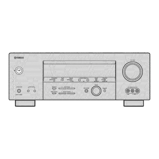
- Page 8 ® ® STANDBY/ON Turns on this unit or sets it to the standby you turn on this unit, you will hear a click and there will be a 4 to 5-second delay before this unit can reproduce sound. In standby mode, this tulit consumes a small amount of power in order to receive infrared-signals from the remote control.
- Page 9 VIDEO AUX jacks Input audio and video signals from a portable source such as a game console. To reproduce signals from these jacks, select V-AUX VOLUME Controls the output level of all audio This does not affect the RE(? OUT level. (-_ PHONES (SILENT CINEMA)
- Page 10 |_I];|I=_I]I_7*_T;II|_I];[liJI[I];J: This section describes the function of each control on the remote control used to control this unit. To operate other components, see "REMOTE CONTROL page 60. © DTV/CBL --TV-- MUT[ INPUT STEREO NUS_C ENI'ERrAIN @@C9 _YANAHA Infrared Outputs infrared FEATURES"...
- Page 11 Selects the AMP anode. You must select the AMP anode to control the main unit. VOLUME Increases or decreases the volume level. MUTE Mutes the sound. Press again to restore the audio output to the previous volume level. IF STRAIGHT, ENT.* Switches the sound fields off or on.
- Page 12 Decoder indicators When any of this unit's decoders function, indicator lights up. VIRTUAL indicator Lights up when Virtual CINEMA DSP is active (see page 30). SILENT CINEMA indicator Lights tip when headphones are connected field program is selected (see page 25). Input source indicators...
- Page 13 K 96/24 indicator Lights up when a DTS 96/24 signal is input to this unit. LFE indicator Lights up when the input signal contains the LFE signal. M Input channel indicators/speaker Indicate the channel components of the cun'ent digital input signal. Indicate the number of speakers connected in SPEAKERS (page 22), or indicate the channel being adjusted in SP LEVEL (page 55).
- Page 14 @@-@ s,@@ DIGITAL INPUT jacks See pages 15, 17 and 18 for details. MULTI CH INPUTjacks See page 16 for connection information. Video componentjacks See pages 15 and 17 for connection XM jack See page 39 for connection information. AC OUTLET(S) Use to supply power to your other AiV components (see page 20).
- Page 15 1.8 m (6 ft) above such as the YAMAHA Active Subwoofer System, is effective not only fi'om any or all channels, of the LFE (low- channel...
- Page 16 Be sure to connect the left channel '%" (red) and ... (black) properly. _aulty, no sound will be heard from the speakers, polarity of the speaker connections will be unnatural and lack bass. [o,Ta l lj l [oJ_ _t • Before connecting the speakers, power of this unit is off.
- Page 17 Connect the YAMAHA SW-P3600 subwoofer to these terminals. • SUBWOOFER jack Connect a snbwoofer with built-in amplifier, YAMAHA Active Servo Processing Subwoofer to this jack when you do not use the YAMAHA P3600 subwoofer. Front speakers (A) Right Left Surround speakers Right ®® Front Center...
- Page 18 [_aY#H£oTJ,'l Do not connect this unit or other components power until all connections between complete. • Cable indications For analog signals left analog cables right analog cables For digital signals optical cables coaxialcables For video signals video cables component video cables •...
- Page 19 _Olilil_*llloli_ • Connections for DVD playback Be sure to connect ?'our video sottrce components in the same x_ay you connect ?'our video monitor to this unit. For example, if you connect your video monitor to this unit using a VIDEO connection, connect ?'our video source components to this unit using the VIDEO connections.
- Page 20 |_'li'li'l_*tli'li'l • Connecting to the MULTI CH INPUT jacks This unit is equipped with 6 additional SUBWOOFER) tbr discrete multi-channel amplifier. Connect the output jacks on your multi-format match the left and right outputs to the left and right input jacks •...
- Page 21 • Connections for other video components Be sure to connect ?'our xideo source components in the same way you connect your video lnonitor to this unit. For example, if you connect your video lnonitor to this unit using a VIDEO connection, connect ?'our video source components to this unit using the VIDEO connections.
- Page 22 |'l'li'li'l:l*llNi'_ • Connections for audio components Audio out CD player Coaxial Audio out_ Audio m MD recorder tapedeck...
- Page 23 AM antenna is connected to this tulit. • A properly installed ontdoor antenna provides clearer reception than an indoor one. If you experience poor reception quality\ an outdoor antenna may improve the quality. Consult the nearest authorized YAMAHA dealer or service center about ontdoor antennas. _'li'l,"l_qlPl,'#...
- Page 24 |*_'li'li't_*lIPh'_ • Connecting the AC power cord Plug the power cord into an AC wall outlet. OUTLET(S) (SWITCHED) • Use these outlets to connect the power other components to this unit. Power to the AC OUTLET(S) is controlled by this unit's STANDBY/ON (or SYSTEM POWER and STANDBY).
- Page 25 The basic setup feature is a useful way to set up your system quickly and with minimal effort. • If you wish to confi_lre the unit manually using more precise acliustments, use the detailed parameters in SOUND MENU (page 55) instead of using BASIC SETUP. •...
- Page 26 1%1-'/(tFt:ilq' Press d to display the SPEAKERS parameter. Pressj / i to select the number connected. SPEAKERS..5spk Choices Display Front L'R 2spk 3 sp k _ _c'RJ Front L/R, Front L,'R, 4spk [2} [_] [_] Front L,'R. Centel 5spk Press d to display SET/CANCEL.
- Page 27 • To balance the speaker levels Perform the following steps after step 13 (see page 22). VAUX DW,¢_t DVr_ _D,¢D_ The unit outputs the test tone from the selected and the left front (or left surround) speaker indicator of the speaker currently outputting flashes...
- Page 28 Press STANDBY/ON (or SYSTEM POWER on the remote control) to turn on the power. Remotecontrol Front panel Turn on the video monitor connected to this unit. Press SPEAKERS A or B (or press AMP to select the AMP mode, then press SPEAKERS A or B on the remote control).
- Page 29 Select a sound field program h repeatedly Press PROGRAM to select the AMP mode, then press one of the sound field program buttons on the remote a sound field progrmn. (See page 48 for details sound field programs.) Front panel ',AM_ Remote control...
- Page 30 li"A*l%|'t, • Selecting MULTI CH INPUT Press MULTI CH INPUT (or MULTI CH IN on the remote control) so that "MULTI CH INPUT" appears in the front panel display. mULT_CH _NPUT Front panel MULTI CH INPUT When "MULTI CH INPUT" is shown in the front panel displa): no other source can be played.
- Page 31 • Remote control operation Press AMP to select the AMP mode, then press one of the sound field program buttons repeatedly to select the desired program. The name of the selected program appears in the front panel display. VAUX DIVJ¢_L r4VD MD_D_ Program name...
- Page 32 li'lA*d%|'tl • Some 6.l-channel compatible discs do not have the flag of a 6. l-channel signal which this trait can automatically ellioy these kinds of discs with the extended surronnd mode. select "MATRIX". • The extended surround mode is not available in the ±bllowing cases: When "SUR.
- Page 33 • Listening to high fidelity stereo sound (Direct Stereo) Direct Stereo allows you to bypass this unit's DSP processors to enjoy pure high fidelity channel PCM and analog sources. Press PROGRAM / h repeatedly to select the AMP mode, then press DIRECT ST.) to select "Direct Stereo".
- Page 34 lililiqil'tl • Listening to unprocessed input signals In STRAIGHT mode, two channel output from only the front left and right speakers. channel sources are decoded straight channels without any additional effect processing. Press STRAIGHT (or press AMP to select mode, then press STRAIGHT control) to select...
- Page 35 • When playing a DTS-CDiLD. be sure to set the INPUT MODE to DTS. • If the digital output data of the player has been processed in an?" wa3: you may not be able to perfom_ DTS decoding even if you make a digital connection between this unit and the player depending on the player.
- Page 36 There are 2 tuning methods; automatic Automatic tuning is effective when station signals strong and there is no interference. • Automatic tuning Rotate INPUT to select TUNER as the input SOUrCe. INPUT Press FM/AM to select the reception "FM" or "AM" appears in the front panel display. FM/A_ Press TUNING MODE (AUTO/MAN'L so that the AUTO indicator lights up in the...
- Page 37 tuning • Manual If the signal fi'om the station you want to select is weak, tune into it manually. Manually tuning into an FM station will automatically switch the tuner to monaural to increase the signal quality. Select TUNER and the reception band following steps 1 and 2 as described in "Automatic tuning".
- Page 38 llJVllglliqi'fli'F Press and hold MEMORY (MAN'L/AUTO for more than 3 seconds. The preset number, the MEMORY and AUTO indicators flash. After about 5 seconds, automatic presetting starts from the frequency currently displayed and proceeds toward the higher frequencies. MEMORY vAux m'c,c_t ovrJ _'i.L...
- Page 39 Press PRESET/TUNING/CH preset station number (1 to 8) while the MEMORY indicator is flashing. Press h to select a higher preset station number. Press I to select a lower preset station number. -: J PRESET TUN_t_G,CH I > VAU× BTV,¢It t_DCBR _ B-_ ,_u, v ¢5 M _"...
- Page 40 |lt't_llg_|iq*'(l*'F Press PRESET/TUNING/CH PRESET/CH u / cl on the remote select a preset station number The preset group and number panel display along with the station band, frequency and the TUNED indicator lights up. -: i PRESET_TU_I_G/C_ I > _''"L ...
- Page 41 Select preset station "A5" using AIBICIDIE and PRESET/TUNING/CH I / In. "A5" and the MEMORY indicator flash in the front panel display. A/B/C/D/E "= Press PRESET/TUNING (EDIT) again. The stations stored at the two preset assignments exchanged. pRE_ETrl U_I_ VAUX IIgtIIL _1111 TUNER...
- Page 42 XM Satellite Radio is the satelliteradio service with millions of listeners across the U.S., broadcastinglive daily.XM's channel lineup includesmore than 130digital channelsof choice fromcoast to coast: 68 commercial-free music claaunels,featuring hip hop to opera, classical to conntrs_bluegrass to blues: 33 channels ofpremier sports,talk, comedy, children's and entertailnnemprogranmaing;...
- Page 43 • Remote control functions The ±bllowing controls are only available when the unit is in the TLLNER mode. To switch to the TUNER mode, press TUNER to select TL_TNERas the input source. Numeric buttons (All Channel Search or Category Use 1 to 9 and 0 to enter a channel number (Preset Search...
- Page 44 D :4 j __ l ___ | l lll ll ll lll lll l_r__ l ll [lll ; l l ; [_" Press PRESET/TUNING/CH PRESET/CH u / cl on the remote select channel "0". Front panel You cannnot select channel "0" if the "All Channel Search mode" (see page 41) is not selected.
- Page 45 • Switching XM information You can display XM infomlation (such as channel number.name, category, or artist name/song title) for the channel currently selected in the front panel display. Press DISPLAY on the unit (or remote control during the TUNER mode) repeatedly to toggle between the following XM information display modes.
- Page 46 D :4 j __ l __" i l lll ll ll lll lll l_r_" l ll [lll ; l l ; [_" To change the channel category, press CATEGORY (or A-E/CAT.j control) repeatedly. A/B/C/D/E CATEGOR¥_ Frontpanel To search a channel within all channels, press PRESET/TUNING/CH PRESET/CH u / d on the remote control)
- Page 47 • Preset Search mode Prior to selecting a preset channel in the Preset mode, you should preset XM Satellite details, see "Setting XM Satellite Radio preset channels" on page 44. All preset channels (AI to E8) recalls Preview" by the factory setting.
- Page 48 DJ4j_l__,|lllllllllllllll_r_,lJllmlllll;ll;lt Press the numeric buttons desired channel number. For example, to enter the number numeric buttons as shown below. STEREO MUSIC The display changes as follovcs. v Au× _t_t ".. :""=i'iY VAIJ× D_,_t ",. ,""= i' } Y ...i..d. vAux DTVSe_t •:"...
- Page 49 While the MEMORY indicator is flashing, press CATEGORY (or A-E/CAT.j remote control) to select a preset group (A to E). The group letter appears. A/_/C/D/E Front panel Remote vAu× _VS¢_L _D,¢D_ TU_ER , C_ Preset group While the MEMORY indicator is flashing, press PRESET/TUNING/CH I / h (or...
- Page 50 |:4j_lf__'|l:lllll|l:l=__'lJHm|ll]A_ll;[, " • Status and error messages If an operation takes longer than usual display. In this case, read the cause Message CHECK ANTENNA Tile XM Connect and Play digital antenna connected, UPDATING The XM use_ enc_wption code is being updated NO SIGNAL The signal is too weak LOADING...
- Page 51 Recording adjustments and other operations perlbrmed from the recording components. operating instructions for those components. Turn on the power of this unit and all connected components. Select the source component you want to record from. INPUT Front panel Remote Start playback (or select a broadcast station) on the source component.
- Page 52 70-ram and multi-channel sotmd field is made to be similar to that of the newest reverberations of the sound field itself are restrained playback with a YAMAHA digital sound field your playback environments found in _amous and Dolby Surromld sottrces.
- Page 53 Remote control Program button MOV1E TH EATER: Genera SUR. STANDARD SUR. ENHANCED Features CINEMA DSP p_ocessing This pro_am is for iep_oducing and multi-channel soundtrack fihns, and is characterized sound field Standardpiocessingfor the selecteddecoder. Enhancedprocessingfor the selecteddecodeL Sources sounds flora 70-mln MULTI by soft and extensive 2-(H...
- Page 54 You can select from the following sound fields when playing Program selection methods vary depending on sound field program select sound field programs, see "Selecting Remote control Program button STEREO: 2ch SLereo STEREO: 5ch Stereo Mum [ C: Ha [ I i n V i enna Mum [ C: gttm...
- Page 55 Use this feature to automatically set this unit in the standby mode after a certain amount of time. The sleep timer is useful when you are going to sleep while is playing or recording a source. The sleep timer also automatically turns off any external components...
- Page 56 You can adjust the output level of each speaker listening to a music source. This is also possible playing sources through the MULTI Please note that this operation will override adjustments made in "BASIC SETUP" LEVEL" (page 55). Press AMP. Press LEVEL repeatedly...
- Page 57 You can use the following parameters unit operates. Change the initial settings erlvironmerlt. • BASIC SETUP to quickly setup basic system parameters • MANUAL SETUP to adjust speaker system settings 1 SOUND MENU to manually adjust speaker setting, video signal processing delays when...
- Page 58 l_=l|i'll=Jl, r Use the remote control to access and adjust each parameter. You can change SET MENU parameters while the unit is reproducing sound. You calmot change some SET MENU parameters while the tulit is in either cinema or nmsic night listening mode. Press AMP.
- Page 59 Use to manually adjust any speaker setting or compensate for video signal processing delays when using LCD monitors or projectors. Most of the SOUND parameters are set automatically when you perform "BASIC SETUP" (see page 21). • Speaker settings A)SPEAKER SET Use to manually adjust any speaker setting.
- Page 60 l_=l|_'ll=il, r Speaker distance C)SP • Use this feature to manually input the distance speaker and adjust the delay applied Ideally, each speaker should be the same distance main listening position. However, this is not possible most home situations. Thus, a certain must be applied to the sound from each speaker sound will arrive at the listening...
- Page 61 • Audio settings G)AUDIO SET Use to customize this units overall audio Muting type MUTE TYP. Use to adjust how nmch the mute function output volume. FULL, Choices: 20dB • Select FULL to completely halt all output of sound. • Select 20dB to reduce the current volume Audio...
- Page 62 l_=l|Fll=ii'r • Input mode B) INPUT MODE Use this feature to designate the input mode connected to the DIGITAL INPUT jacks when you tuna on this unit (see page 30 for details about the input mode). Choices: AUTO, LAST • Select AUTO to allow this unit to automatically the type of input signal and select the appropriate mode.
- Page 63 Zoneset D)MULTI ZONE • Use to specify the location of speakers connected to the SPEAKERS B terminals. Speaker B setting SP B Use this feature to select the location connected to the SPEAKERS B terminals. Choices: FRONT, ZONE B • Select FRONT to turn on/off SPEAKERS...
- Page 64 Component control area You can cont!ol up to 7 different components by setting appropriate remote control codes (see page 61). components made by YAMAHA with the appropriate remote control can be used to control other has a different Ihnction components.
- Page 65 *2 Yon can only set TV remote control codes for the DTVi(BL button. You may not be able to operate your YAMAHA component even if a YAMAHA remote control code is initially set as listed above. In this case. try to set other YAMAHA remote control code(s). While...
- Page 66 Once you set the appropriate remote can use this remote to control your other components. Note that some buttons may not correctly selected component. Use the input selector buttons select the component you want to operate. control automatically switches to the appropriate mode for that component.
- Page 67 This ability to create sound fields at will is exactly what YAMAHA has done with the digital sound field processor. You can enjoy good quality parameters.
- Page 68 |,:ll] l l l] [L'm."Ie] lJ A_ l lJ _ l :lll ".[:_: Tdd :_l l :l Zi Repeat steps 2 through 4 as necessary change other program parameters. You cannot change parameter values when "MEMORY GUARD" is set to ON. If you want to change the parameter values, set "MEMORY GUARD"...
- Page 69 You can adjust the values of certain digital sound field parameters so the sound fields are recreated accurately in your listening room. Not all of the following parameters are found in every program. • DSP LEVEL (DSP level) Function: Adjusts the level of all the DSP effect sounds within a nan'ow range. Description: Depending on the acoustics of your listening room, you may want to increase or decrease the DSP effect level relative to the level of the direct sound.
- Page 70 For 5ch Stereo: Function: These parameters Controlrange: 0 to 100% • CT LEVEL (Center level) • SL LEVEL (Surround left level) • SR LEVEL (Surround right level) For PRO LOGIC II Music: • PANORAMA (Panorama) Function: Sends stereo signals Choices: OFF, ON •...
- Page 71 Refer to the chart below when this unit does not function or if the instruction below does not help, set this unit to the standby mode, nearest authorized YAMAHA dealer or service center. • General Problem This unit fails to turn...
- Page 72 IIIf;,e]l]:l|3.v_:[mlm]lll;[, Problem The sound suddenly The protection goes off, because of a short circuit, Tile sleep timm has mined the unit off. Tile sound is ranted. Incorrect cable COlmentions Only the speaker one side can be heard. Incorrect balance Only the center When playing speaker outputs CINEMA...
- Page 73 Problem Dolby Digital or DTS The connected sources cannot output Dolby Digital played. (Dolhy Digital signals or DTS indicator Tile input mode is set to ANALOG the front panel display does not light up.) A "humming" sound Incorrect cable coimections can be heard.
- Page 74 IIl=;,e]l]:l|3.v_:[mImJIiI;[, • Tuner Problem The characteristics FM stereo reception noisy. broadcasts when the transmitter the antenna There is distortion, The:e is multipath clear reception cannot be obtained even with a good FM antenna. The desired station The signal is too weak. cannot be tuned in with...
- Page 75 If you want to reset all of your unit's parameters reason, do the following. This procedure ALL parameters, including the SET MENU, and tuner presets. Be sure this unit is in standby mode. STANDBY/ON STRAIGHT (EFFECT) With the unit in standby mode, hold down STRAIGHT (EFFECT) on the front panel and...
- Page 76 • Dolby Digital Dolby Digital is a digital sun'ound sound system that gives you completely independent multi-channel front channels (left, center, and right), stereo channels, Dolby Digital provides channels. With an additional channel effects, called LFE (low frequency a total of 5.1-channels (LFE is counted using 2-channel stereo for the sun'ound...
- Page 77 Based on a wealth of actually measured data, YAMAHA CINEMA DSP uses YAMAHA original sound field technology to combine Dolby Pro Logic, Dolby Digital and DTS systems to provide the visual and audio experience of movie theater in the listening room of your own home.
- Page 78 Component video signal • With the component video signal system, is separated into the Y signal for the luminance and PF_signals for the chrominance. reproduced more faithfully with this system of these signals is independent. The component also called the "color difference signal"...
- Page 79 AUDIO SECTION • Minimmn RMS Output Powe! fb! Front Centel, Sunound 1 kHz, 09% 6 _ ... • Mininmm RIMS Powe! for Subwoofer Outpllt 30 Hz, 6 _} ... • Dynamic Power (IHF) 6/4/2 _ ... • Damping Factor (IHF) 20 Hz to 20 kHz, 8 _ ...
- Page 80 135 MILNKR AVE SCARBOROUGH, YAMAHA ELECTRONIK EUROPA e.m.b.H. S]EMENSSTR YAMAHA ELECTRONIQUE FRANCE S.A. RUE AMBROISE YAMAHA ELECTRONICS (UK) LTD. YAMAHA HOUSE 200 RICKMANSWORTH YAMAHA SCANDINAVIA A.B. J A WETTKRGRENS GATA I YAMAHA MUSIC AUSTRALIA PTY, LTD /7 33 MARKET CODES Pioneer 226.
- Page 81 135 MILNER AVE SCARBOROUGH, YAMAHA ELECTRONIK EUROPA G.m.b.H. SIE_'iENSSTR YAMAHA ELECTRONIQUE FRANCE S.A. RUE AMBROISE YAMAHA ELECTRONICS (UK) LTD. YAMAHA HOUSE 200 RICKMANSWORTH YAMAHA SCANDINAVIA A.B. J A WETTERGRENS GATA I YAMAHA MUSIC AUSTRALIA PTY, LTD /7 33 MARKET AVE,...