Table of Contents
Advertisement
Quick Links
AV Amplifier
Amplificateur Audio-Vidéo
PURE DIRECT
REC OUT/ZONE 2
SOURCE/REMOTE
DTV/LD
DVD
CABLE
MD/TAPE
SPEAKERS
2CH/MULTI CH
A
B
SAT
CD-R
INPUT SELECTOR
VCR 1
CD
VCR 2
TUNER
DVR
PHONO
VIDEO AUX
STANDBY
/ON
SILENT
OPTIMIZER
MIC
PHONES
OWNER'S MANUAL
MODE D'EMPLOI
BEDIENUNGSANLEITUNG
GB
VOLUME
MULTI JOG
BALANCE
MULTI CH
DSP
INPUT MODE
INPUT
STRAIGHT
PROGRAM
TONE
CONTROL
EFFECT
VIDEO AUX
S VIDEO
VIDEO
L
AUDIO
R
OPTICAL
Advertisement
Table of Contents

Related Manuals for Yamaha DSP-Z9


Summary of Contents for Yamaha DSP-Z9
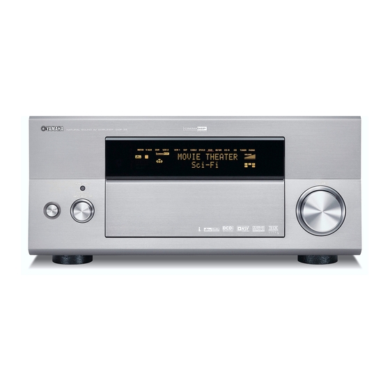
- Page 1 AV Amplifier Amplificateur Audio-Vidéo PURE DIRECT REC OUT/ZONE 2 SOURCE/REMOTE MULTI JOG DTV/LD CABLE MD/TAPE SPEAKERS MULTI CH 2CH/MULTI CH CD-R INPUT MODE INPUT STRAIGHT PROGRAM INPUT SELECTOR VCR 1 VCR 2 TUNER EFFECT PHONO VIDEO AUX STANDBY SILENT OPTIMIZER VIDEO AUX PHONES S VIDEO...
- Page 2 Using this unit with a higher voltage than specified is dangerous and may cause fire, damage to this unit, and/or personal injury. YAMAHA will not be held responsible for any damage resulting from use of this unit with a voltage other than specified.
-
Page 3: Table Of Contents
INTRODUCTION FEATURES ... 2 GETTING STARTED... 3 Supplied accessories ... 3 Installing batteries in the remote controls... 4 CONTROLS AND FUNCTIONS... 5 Front panel ... 5 Remote control... 7 GUI remote control... 8 Using the remote controls ... 9 Front panel display... 10 Rear panel ... -
Page 4: Features
Surround: 170 W + 170 W Surround back: 170 W + 170 W Presence: 50 W + 50 W Sound field features Proprietary YAMAHA technology for the creation of sound fields THX Ultra 2 Dolby Digital/Dolby Digital EX decoder Dolby Pro Logic/Dolby Pro Logic II/Dolby Pro Logic IIx decoder DTS/DTS ES Matrix 6.1, Discrete 6.1/DTS 96/24... -
Page 5: Getting Started
Supplied accessories Please check that you received all of the following parts. Remote control MACRO TRANSMIT RE-NAME CLEAR LEARN MACRO SYSTEM STANDBY V-AUX POWER TUNER PHONO CABLE MD/TAPE CD-R DTV/LD VCR 1 VCR 2 Batteries (3) MULTI CH IN PURE DIRECT TITLE ENTER SOURCE... -
Page 6: Installing Batteries In The Remote Controls
GETTING STARTED Installing batteries in the remote controls Notes on batteries • Change all of the batteries if you notice the following conditions: the operation range of the remote control decreases, the indicator does not flash or its light becomes dim. •... -
Page 7: Controls And Functions
CONTROLS AND FUNCTIONS Front panel PURE DIRECT SPEAKERS 2CH/MULTI CH INPUT SELECTOR STANDBY 1 STANDBY/ON Turns on this unit or sets it to the standby mode. When you turn on this unit, you will hear a click and there will be a delay of a few seconds before this unit can reproduce sound. - Page 8 CONTROLS AND FUNCTIONS 0 MULTI JOG Rotate to select or adjust items when used with the DSP PROGRAM, BALANCE or TONE CONTROL buttons. A BALANCE Adjusts the left/right balance of the front, presence, surround and surround back speakers. B TONE CONTROL Press this button before rotating MULTI JOG to adjust the bass/treble balance for the front left/right, center and subwoofer channels (see page 38).
-
Page 9: Remote Control
Remote control This section describes the functions of each control on the remote control. See “REMOTE CONTROL FEATURES” on page 80 to operate other components with this remote control. TRANSMIT RE-NAME CLEAR LEARN MACRO SYSTEM POWER STANDBY V-AUX TUNER CABLE MD/TAPE CD-R DTV/LD... -
Page 10: Gui Remote Control
CONTROLS AND FUNCTIONS G LEARN Used for setting up the manufacturer code or for programming the functions of other remote controls (see pages 81 and 82). H MACRO Used to program a series of operations for control by a single button (see page 84). I MACRO ON/OFF Turns the macro function on and off. -
Page 11: Using The Remote Controls
Using the remote controls PURE DIRECT REC OUT/ZONE 2 VOLUME SOURCE/REMOTE MULTI JOG BALANCE DTV/LD CABLE MD/TAPE SPEAKERS MULTI CH 2CH/MULTI CH INPUT MODE INPUT STRAIGHT PROGRAM CD-R INPUT SELECTOR VCR 1 TONE CONTROL VCR 2 TUNER EFFECT PHONO VIDEO AUX STANDBY SILENT OPTIMIZER... -
Page 12: Front Panel Display
CONTROLS AND FUNCTIONS Front panel display MULTI CH V–AUX VCR 2 MATRIX DISCRETE HiFi DSP VIRTUAL NIGHT SILENT DIGITAL OPTIMIZER SLEEP ZONE2 1 i.LINK indicator Lights up when this unit is playing back i.LINK signals. 2 Decoder indicators When any of this unit’s decoders function, the respective indicator lights up. -
Page 13: Rear Panel
Rear panel – PRESENCE SURROUND SURROUND CENTER FRONT FRONT /ZONE 2 BACK SPEAKERS (SINGLE) CENTER PHONO SURROUND SURROUND SUBWOOFER FRONT PURE DIRECT IN(PLAY) BACK TUNER MD/TAPE MULTI CH INPUT 2CH IN COMPONENT VIDEO DTV/LD VCR1 1–MONITOR OUT–2 DIGITAL INPUT DTV/LD CD-R q RF—... -
Page 14: Speaker Setup
Ideally, they should be positioned at the same width as the front speakers. Subwoofer The use of a subwoofer, such as the YAMAHA Active Servo Processing Subwoofer System, is effective not only for reinforcing bass frequencies from any or all channels,... -
Page 15: Speaker Connections
Di-pole speaker layout Either di-pole or direct radiating speaker types can be used for THX surround. If you choose di-pole speakers, please place the surround and surround back speakers according to the speaker layout below. : Di-pole speaker : Direction of di-pole speaker Speaker connections Be sure to connect the left channel (L), right channel (R), “+”... - Page 16 SPEAKER SETUP Presence right speaker Center speaker – PRESENCE SURROUND SURROUND CENTER FRONT /ZONE 2 BACK SPEAKERS Surround back Surround right speaker right speaker Front right Front left speaker (A) speaker (A) Front speakers (B) – FRONT Speaker layout Left Presence subwoofer left...
- Page 17 Connect a surround speaker system to these terminals. SUBWOOFER jacks Connect one or two subwoofer(s) with built-in amplifier, such as the YAMAHA Active Servo Processing Subwoofer System, to the jack(s). SURROUND BACK terminals Connect a surround back speaker system to these terminals.
-
Page 18: Connections
CONNECTIONS Connecting components CAUTION Do not connect this unit or other components to the mains power until all connections between components are completed. Signal directions and cable indications audio signal direction video signal direction For analog signals left analog cables right analog cables For digital signals optical cables... -
Page 19: Connecting Video Components
Connecting video components Connections for DVD playback – PRESENCE SURROUND SURROUND CENTER /ZONE 2 BACK SPEAKERS (SINGLE) CENTER PHONO SURROUND SURROUND SUBWOOFER FRONT PURE DIRECT BACK MULTI CH INPUT 2CH IN COMPONENT VIDEO DTV/LD VCR1 DIGITAL INPUT DTV/LD q RF— (AC-3) COAXIAL –... - Page 20 CONNECTIONS Connecting to the MULTI CH INPUT jacks This unit is equipped with 8 additional input jacks (left and right FRONT, CENTER, left and right SURROUND, left and right SURROUND BACK and SUBWOOFER) for discrete multi-channel input from a universal disc player, external decoder, sound processor or pre-amplifier.
- Page 21 Connections for digital TV broadcasts or LD playback – PRESENCE SURROUND SURROUND CENTER /ZONE 2 BACK SPEAKERS (SINGLE) CENTER PHONO SURROUND SURROUND SUBWOOFER FRONT PURE DIRECT BACK MULTI CH INPUT 2CH IN COMPONENT VIDEO DTV/LD VCR1 DIGITAL INPUT DTV/LD q RF— (AC-3) COAXIAL A demodulator circuit is built into the Dolby Digital RF input so you can connect it directly to the Dolby Digital RF signal output on...
- Page 22 CONNECTIONS Connections for cable TV broadcasts – PRESENCE SURROUND SURROUND /ZONE 2 BACK SPEAKERS (SINGLE) CENTER PHONO SURROUND SURROUND SUBWOOFER FRONT PURE DIRECT BACK MULTI CH INPUT 2CH IN COMPONENT VIDEO DTV/LD DIGITAL INPUT DTV/LD q RF— (AC-3) COAXIAL – CENTER FRONT FRONT...
- Page 23 Connections for satellite broadcasts – PRESENCE SURROUND SURROUND CENTER /ZONE 2 BACK SPEAKERS (SINGLE) CENTER PHONO SURROUND SURROUND SUBWOOFER FRONT PURE DIRECT BACK MULTI CH INPUT 2CH IN COMPONENT VIDEO DTV/LD VCR1 DIGITAL INPUT DTV/LD q RF— (AC-3) COAXIAL – FRONT FRONT IN(PLAY)
- Page 24 CONNECTIONS Connections for VCR playback and recording – PRESENCE SURROUND SURROUND /ZONE 2 BACK SPEAKERS (SINGLE) CENTER PHONO SURROUND SURROUND SUBWOOFER FRONT PURE DIRECT BACK MULTI CH INPUT COMPONENT VIDEO DTV/LD DIGITAL INPUT DTV/LD q RF— (AC-3) COAXIAL Connections to VIDEO AUX jacks (on the front panel) Use these jacks to connect any video source, such as a game console or video camera, to this unit.
- Page 25 Connections for DVD recorder playback and recording SURROUND CENTER FRONT FRONT SPEAKERS CENTER IN(PLAY) OUT(REC) UBWOOFER FRONT PURE DIRECT TUNER MD/TAPE MULTI CH INPUT 2CH IN COMPONENT VIDEO VCR1 1–MONITOR OUT–2 DIGITAL INPUT CD-R AC IN – AUDIO IN(PLAY) OUT(REC) CD-R DTV/LD 1–MONITOR OUT–2...
-
Page 26: Connecting Audio Components
CONNECTIONS Connecting audio components Connections for audio playback Audio out – PRESENCE SURROUND /ZONE 2 BACK (SINGLE) PHONO SURROUND SURROUND BACK DTV/LD DTV/LD q RF— (AC-3) COAXIAL Connecting a turntable PHONO jacks are for connecting a turntable with an MM or high-output MC cartridge. - Page 27 Connections for audio playback and recording – PRESENCE SURROUND SURROUND /ZONE 2 BACK SPEAKERS (SINGLE) CENTER PHONO SURROUND SURROUND SUBWOOFER FRONT BACK MULTI CH INPUT COMPONENT VIDEO DTV/LD DIGITAL INPUT DTV/LD q RF— (AC-3) COAXIAL Optical in MD/tape Audio out Audio in –...
- Page 28 Presence channel line output jacks. 6 SUBWOOFER jacks Connect one or two subwoofer(s) with built-in amplifier, such as the YAMAHA Active Servo Processing Subwoofer System, to these jacks. Notes • Adjust the volume level of the subwoofer with the control on the subwoofer.
-
Page 29: Connecting The Power Supply Cord
Connecting the power supply cord AC IN AC OUTLETS AUDIO IN(PLAY) OUT(REC) IN(PLAY) OUT(REC) IN(PL DTV/LD VCR 1 VCR 2 VIDEO DTV/LD VCR 1 VCR 2 DIGITAL OUTPUT MD/TAPE ZONE 2 (AUD OPTICAL COAXIAL VOLTAGE SELECTOR VOLTAGE SELECTOR AC IN –... -
Page 30: Speaker Impedance Setting
CONNECTIONS Speaker impedance setting CAUTION If you are using 6-ohm speakers, set the impedance to 6 ohms as follows before turning on the power. Be sure this unit is in the standby mode. On the front panel, while holding down SPEAKERS A, press STANDBY/ON. -
Page 31: Using The Gui Remote Control
USING THE GUI REMOTE CONTROL GUI remote control operations The GUI (graphical user interface) remote control provides a simple and convenient way to control this unit while viewing a GUI display on your video monitor. You can use the following steps to: •... - Page 32 USING THE GUI REMOTE CONTROL Use k/n/l / h to navigate through the categories, menus and parameters. To select the parameter you want to adjust press ENTER. Use k/n/l / h to adjust the parameters. For details about each parameter see page 55. When finished, press EXIT to exit.
-
Page 33: Auto Setup
Introduction This unit employs YAMAHA Parametric Room Acoustic Optimizer (YPAO) technology which lets you avoid troublesome listening-based speaker setup and achieves highly accurate sound adjustments. The supplied optimizer microphone collects and analyzes the sound your speakers produce in your actual listening environment. -
Page 34: Starting The Setup
AUTO SETUP Starting the setup For best results, make sure the room is as quiet as possible during the auto setup procedure. If there is too much ambient noise, the results may not be satisfactory. If your subwoofer can adjust the output volume and crossover frequency, set the volume to about half way (or slightly less), and set the crossover frequency to the maximum. - Page 35 For Equalizing, select: Skip To skip the selected item and perform no adjustments. Flat To average the frequency response of all speakers. Recommended if all of your speakers are of similar quality. Front To adjust the frequency response of each speaker in accordance with the sound of your front speakers.
-
Page 36: Confirming The Results
AUTO SETUP Confirming the results You can confirm the results of each analysis. If you set Setup Type to Auto. The results are displayed after all items have been analysed. • Press n and select Setup to set the measured values. •... - Page 37 Troubleshooting for the auto setup procedure Before auto setup Error message Connect MIC! Optimizer microphone is not connected. Unplug Phones! Headphones are connected. No Setup Menu! No setup menu items have been selected. Memory Guard! This setting is protected. During auto setup Press l / h to display detailed information for individual errors.
- Page 38 AUTO SETUP After auto setup The following warning messages are displayed after analysis is complete to inform you of possible problems. We recommend that you check the contents of each message, then select Retry to try the auto setup procedure again. Warning message W1:Out of Phase Speaker polarity is incorrect.
-
Page 39: Playback
Basic operations PURE DIRECT REC OUT/ZONE 2 SOURCE/REMOTE MULTI JOG DTV/LD CABLE MD/TAPE SPEAKERS MULTI CH 2CH/MULTI CH INPUT MODE INPUT STRAIGHT PROGRAM CD-R INPUT SELECTOR VCR 1 VCR 2 TUNER EFFECT PHONO VIDEO AUX STANDBY SILENT OPTIMIZER VIDEO AUX PHONES S VIDEO VIDEO... - Page 40 PLAYBACK Select a sound field program if desired. Press DSP PROGRAM then rotate MULTI JOG (or on the remote control, set 10KEY/AMP to AMP, then press one of the sound field program buttons repeatedly) to select a sound field program. (See page 48 for details about sound field programs.) MULTI JOG 10KEY...
-
Page 41: Selecting Sound Field Programs
Selecting MULTI CH INPUT Press MULTI CH INPUT so that “Input MULTI CH” appears in the front panel display and “MULTI CH ON/ OFF” appears on the video monitor. MULTI CH INPUT Front panel Note If you want to select another input source with INPUT SELECTOR (or one of the input selector buttons on the remote control) when “Input MULTI CH”... -
Page 42: Remote Control Operation
PLAYBACK Remote control operation 10KEY/AMP 10KEY STEREO HALL#1 HALL#2 CHURCH JAZZ ROCK MUSIC ENTERTAIN EX/ES MOVIE /DTS NIGHT +100 CHP/INDEX A/B/C/D/E PRESET TV INPUT MUTE TV VOL VOLUME TV MUTE STRAIGHT DISC EFFECT PUSH ON SCREEN SPEAKERS SLEEP TEST Set 10KEY/AMP to AMP, then press one of the sound field program buttons repeatedly to select the desired program. - Page 43 Notes • 6.1/7.1-channel playback is not possible even if EX/ES is pressed in the following cases: – When Surround or Surround Back is set to “None” (see page 68). – When the source being played does not contain surround L/R channel signals.
- Page 44 PLAYBACK Listening at night This mode reproduces dialog clearly while reducing the volume of loud sound effects for easier listening at low volumes or at night. Press NIGHT on the remote control. The NIGHT indicator in the front panel display lights up. Press NIGHT again to cancel.
-
Page 45: Listening To Uncompromising Pure Audio
Listening to uncompromising pure audio PURE DIRECT allows you to enjoy the highest possible fidelity from audio sources connected to the 2CH IN PURE DIRECT or MULTI CH IN jacks. This function bypasses all of this unit's decoders and digital circuitry to provide uncompromised audio fidelity. -
Page 46: Selecting Input Modes
PLAYBACK Selecting input modes This unit comes with a variety of input jacks. Do the following to select the type of input signals you want to use. Select the input source. INPUT SELECTOR Front panel Press INPUT MODE (or INPUT MODE when 10KEY/AMP is set to AMP) to select an input mode. - Page 47 Displaying information about the input source You can display signal information for the audio or video signal currently being input. Remote control operation Press TOP on the GUI remote control. Press n repeatedly to select Signal Info. The signal information appears on the GUI display. Press h to switch between the Audio Info and Video Info screens.
-
Page 48: Recording
RUNNING H/F 1 You can use the REC OUT/ZONE 2 control to record one source while watching and/or listening to another source. Recording adjustments and other operations are performed from the recording components. Refer to the operating instructions for these components. PURE DIRECT REC OUT/ZONE 2 SOURCE/REMOTE... - Page 49 Special considerations when recording DTS software The DTS signal is a digital bitstream. Attempting to digitally record the DTS bitstream will result in noise being recorded. Therefore, if you want to use this unit to record sources that have DTS signals recorded on them, the following considerations and adjustments need to be made.
-
Page 50: Sound Field Program Descriptions
The YAMAHA CINEMA DSP modes are compatible with all Dolby Digital, DTS, and Dolby Surround sources. Set the input mode to Auto (see page 44) to enable this unit to automatically switch to the appropriate digital decoder according to the signal being input. -
Page 51: Dolby Digital
Program THX processing for non EX/ES encoded 5.1 channel sources. This program outputs sound from the surround back L/R speakers using ASA (advanced speaker array) processing. This mode is Ultra2 Cinema only available when you have set up a 7.1 speaker system (i.e. two surround back speakers), and the input signal has surround left and surround right contents. -
Page 52: Pro Logic Ii
SOUND FIELD PROGRAM DESCRIPTIONS Program SUR. STANDARD Indicates that signals are being input through the MULTI CH INPUT jacks. Multi In SUR. STANDARD Dolby Digital processing for signals input through the MULTI CH INPUT jacks. MultiIn+DolbyD SUR. STANDARD Dolby Pro Logic IIx Movie processing for signals input through the MULTI CH INPUT jacks. MltIn+PLIIxMovie SUR. -
Page 53: For Music Sources
For music sources You can select from the following sound fields when playing music sources. Program SUR. STANDARD Dolby Pro Logic II processing for music software. PLII Music SUR. STANDARD Dolby Pro Logic IIx processing for music software. PLIIx Music SUR. - Page 54 SOUND FIELD PROGRAM DESCRIPTIONS Program CHURCH HiFi DSP processing. The acoustic environment of an ordinary church with moderate reverberations. The reverberation lasts 2.5 seconds. This is ideal for reproducing church organ Tokyo and choral music. CHURCH HiFi DSP processing. This program recreates the acoustic environment of a big church located in south Germany.
-
Page 55: Advanced Operation
Selecting the OSD mode You can also display simple text information about this unit’s operation status on your video monitor. Turn on the video monitor connected to this unit. Press ON SCREEN repeatedly to turn the OSD mode on or off. ON SCREEN SPEAKERS SLEEP... -
Page 56: Using The Test Tone
ADVANCED OPERATIONS Using the test tone You can use the test tone feature to manually balance your speaker levels. Please note that this operation will override the level adjustments made in the auto setup procedure (page 31) and “Speaker Level” (page 69). Use the test tone to set speaker levels so that the volume from each speaker is identical when heard from your listening position. -
Page 57: System Options
You can use the following parameters to adjust a variety of system settings and customize the way this unit operates. Change the initial settings (indicated in bold under each parameter) to reflect the needs of your listening environment. Stereo/Surround (Stereo/Surround) Use to manually adjust the sound of your speakers. - Page 58 SYSTEM OPTIONS Video (Video) Use to manually adjust the video parameters. Item Processor Turns on/off the digital video processor. Picture Mode Selects and adjusts the video picture mode suitable for the video picture. Resolution Selects the video resolution. Aspect Selects the aspect ratio. Cross Color Removes noise from image brightness.
-
Page 59: Changing Parameter Settings
Changing parameter settings Use the GUI remote control to access and adjust each parameter. ENTER EXIT You can also perform this operation using the remote control (see page 29). Press TOP on the GUI remote control. Press k/n repeatedly to select a menu, then press h to enter the selected menu. -
Page 60: Input Select
SYSTEM OPTIONS Notes • The available parameters may be displayed on more than one page of the on-screen display. To scroll through pages, press k/n. • You cannot change parameter values when Memory Guard is set to “Guard”. If you want to change the parameter values, set Memory Guard to “Free”... - Page 61 Volume Trim (Volume trim) Use this feature to adjust the level of the signal input to each jack. This is useful if you want to balance the level of each input source to avoid sudden changes in volume when switching between input sources. Input Select >...
- Page 62 SYSTEM OPTIONS Analog Level (Analog level) Use this feature to select the analog input signal. Input Select > input source (DVD, etc.) > Analog Level Choices: STD, HIGH • Normally, select STD. • Select HIGH if the analog input level is higher than normal or the sound seems distorted.
-
Page 63: Manual Setup: Sound
Manual setup: Sound Use this menu to adjust the sound parameters. Press TOP on the GUI remote control. Select Manual Setup, then press h. Select Sound, then press h. Select the desired parameters, then press h to access and adjust. Cinema EQ (Cinema equalizer) Use this feature to adjust PEQ and high frequency levels for any speaker. - Page 64 SYSTEM OPTIONS EQ Select (Equalizer select) Choices: Auto Setup PEQ, Manual GEQ, EQ Defeat • Select Auto Setup PEQ to use the equalizer adjusted in auto setup. • Select Manual GEQ to adjust the built-in 9-band graphic equalizer so that the tonal quality of the presence L/R, center, surround L/R and surround back L/R speakers matches that of the front left and right speakers.
- Page 65 Treble (Treble control) Use this feature to adjust high-frequencies output to your speakers or headphones. Choices: –6 to +6 (dB), Initial: 0 dB You can adjust three frequency bands: 2.5kHz, 3.5kHz, 8.0kHz. Note TONE CONTROL is not effective when: – The THX (page 49) or DIRECT STEREO (page 43) program is selected.
-
Page 66: Manual Setup: Basic
SYSTEM OPTIONS Muting Type (Muting type) Use to adjust how much the mute function reduces the output volume. Choices: Full, –20dB • Select Full to completely halt all output of sound. • Select –20dB to reduce the current volume by 20 dB. Manual setup: Basic Use this menu to set up basic system parameters. - Page 67 THX Set (THX settings) Use to manually adjust the THX settings. Manual Setup > Basic > THX Set > THX Ultra2 SWFR (THX Ultra2 subwoofer) Use this feature to select the THX Ultra2-compatible subwoofer. Choices: No*, Yes THX Ultra2 SWFR Bndry Gain Comp SB Speaker Dist.
- Page 68 SYSTEM OPTIONS Subwoofer Set (Subwoofer set) Use to manually adjust any setting for your subwoofer. Manual Setup > Basic > Subwoofer Set > Config. (Subwoofer configuration) Use this feature to configure the position of the subwoofers. Choices: Front & Rear, Stereo, Monaural, None •...
- Page 69 Bass Out (Bass out) LFE signals carry low-frequency effects when this unit decodes Dolby Digital or DTS signals. These low- frequency signals can be directed to both front left and right speakers, and to the subwoofer (which can be used for both stereo reproduction and sound field programs).
- Page 70 SYSTEM OPTIONS Surround (Surround left/right speakers) Choices: Large, Small, None • Select Large if you have large surround left and right speakers or if a rear subwoofer is connected to the surround speakers. The entire range of the surround channel signal is directed to the surround left and right speakers.
- Page 71 Presence (Presence speakers) Choices: None, Yes • Select None if you do not have presence speakers. This unit directs all presence channel signals to the front left and right speakers. • Select Yes if you have presence speakers. Note When Zone2 Amplifier is set to Internal (see page 78), Presence is automatically set to None.
- Page 72 SYSTEM OPTIONS Speaker Distance (Speaker distance) Use this feature to manually input the distance of each speaker and adjust the delay applied to the respective channel. Ideally, each speaker should be the same distance from the main listening position. However, this is not possible in most home situations.
-
Page 73: Manual Setup: Video
Manual setup: Video Use this menu to adjust the video parameters. If output to the monitor fails while you are performing the parameter setup procedure, the setting of this unit’s video parameters could be incompatible with your video monitor. Press and hold down EXIT on the remote control for 5 seconds or longer to initialize the Video parameters. - Page 74 SYSTEM OPTIONS Picture Mode (Picture mode) Use this feature to select the video picture mode and adjust each mode to suit the video picture. Manual Setup > Video > Picture Mode > Choices: Cinema, Standard, Dynamic • Select Cinema for movies. •...
- Page 75 Aspect (Aspect) Use this feature to select the aspect ratio for the output image converted using the video processing circuit. Manual Setup > Video > Aspect Choices: Through, Auto, 16:9 Normal, 16:9 Zoom • Through: Does not change the aspect ratio of the input video signal in any way.
- Page 76 SYSTEM OPTIONS Aspect conversion examples The images with bold outlines indicate the most suitable setting for each input signal/TV combination. Input signal aspect TV type ratio 16:9 (Letter box) 16:9 16:9 16:9 Note If you want to watch 16:9 software on a 4:3 TV, you need to change the aspect ratio on your TV. Cross Color (Cross color) Use this feature to remove noise from the brightness of displayed images.
-
Page 77: Manual Setup: Option
S Video (S Video) Use this feature to match the video output to the input on your monitor. S1 allows you to automatically resize wide screen software compressed at 4:3 so that it is displayed at 16:9. S2 allows you to automatically resize letter box software so that it is displayed in wide screen mode in addition to the S1 functionality. - Page 78 SYSTEM OPTIONS Surr.Initialize (Surround initialize) Use this feature to initialize the parameters for each sound field program within sound field program groups. When you initialize a sound field program group, all of the parameter values within that group revert to their initial settings.
- Page 79 Use this feature to select the background when no image is input from an external source. If you do not want to display the background, select None. Choices: None, 1(DSP-Z9), 2(Horn), 3(Piano), 4(Gray) Note When Processor is set to Off in the Manual Setup menu, no background is displayed even if no image is input.
-
Page 80: Memory Guard
SYSTEM OPTIONS Zone2 Amplifier (Zone 2 Amplifier) Use to select how the ZONE 2 speakers are amplified. Choices: Internal, External, None • Select External if you connect your Zone 2 speakers through an external amplifier connected to this unit’s ZONE 2 OUTPUT jacks. •... - Page 81 Manual Setup (Manual setup) Choices: Free, Guard • Select Guard to prevent changes to the manual setup parameters. When Guard is set, you can select the Picture Mode (Cinema, Standard or Dynamic), but cannot adjust the settings of each mode. •...
-
Page 82: Remote Control Features
REMOTE CONTROL FEATURES REMOTE CONTROL FEATURES In addition to controlling this unit, the remote control can also operate other A/V components made by YAMAHA and other manufacturers. To control other components, you must set up the remote control with the appropriate manufacturer code(s). -
Page 83: Setting Manufacturer Codes
VCR 1 VCR 2 Note You may not be able to operate your YAMAHA component even if a YAMAHA manufacturer code is initially set as listed above. In this case, try to set another YAMAHA manufacturer code(s). Press an input selector button to select the source component you want to set up. -
Page 84: Programming Codes From Other Remote Controls
• The supplied remote control does not contain all possible manufacturer codes for commercially available AV components (including YAMAHA AV components). If operation is not possible with any of the manufacturer codes, program the new remote control function with the Learn feature (see below) or use the remote control supplied with the component. -
Page 85: Changing Source Names In The Display Window
Press and hold the button you want to program on the remote control for your component until “OK” appears in the display window. Notes • “NG” appears in the display window if programming was unsuccessful. In this case, start over from step 5. •... -
Page 86: Using The Macro Feature
When using macros to operate other components, you will need to program the PLAY button on the control area of that component (see pages 82 and 83) or set a manufacturer code (see page 81). When TUNER is selected as the input source, YAMAHA tuners will play the last station received before the unit was set to the standby mode. - Page 87 Macro operations MACRO MACRO TRANSMIT RE-NAME CLEAR LEARN MACRO MACRO ON/OFF SYSTEM POWER STANDBY V-AUX TUNER PHONO CABLE MD/TAPE CD-R Macro buttons DTV/LD VCR 1 VCR 2 MULTI CH IN PURE DIRECT TITLE Set MACRO ON/OFF to ON. Press a macro button. Notes •...
-
Page 88: Clearing Function Sets
REMOTE CONTROL FEATURES Press MACRO again when the operation sequence you want to program is complete. Memory back-up If the remote control is without batteries for more than 3 minutes, or if exhausted batteries remain in the remote control, the contents of the memory may be cleared. -
Page 89: Clearing Individual Functions
Clearing individual functions Clearing a learned function You can clear the functions learned in programmed buttons for each area. Press an input selector button to select the source component that contains the function you want to clear. The selected component name appears in the display window. -
Page 90: Controlling Components
REMOTE CONTROL FEATURES Controlling components Once you set the appropriate manufacturer codes, you can use this remote to control your other components. Note that some buttons may not correctly operate the selected component. You can use the input selector buttons to select the component you want to operate and automatically switch the remote control to the appropriate control mode for that component. - Page 91 Operating a digital TV (DTV/LD area) or cable/satellite TV (CABLE or SAT areas) DISPLAY POWER Enter TV INPUT (CABLE and SAT only) TV VOL +/– TV MUTE SEARCH, REC, STOP, PAUSE and PLAY operate your VCR without switching the input to VCR 1 if the manufacturer code for your VCR is set in the VCR 1 area.
- Page 92 REMOTE CONTROL FEATURES Operating a CD player (CD area) DISPLAY SEARCH POWER INDEX TV operation Operating a CD recorder (CD-R area) or MD recorder (MD/TAPE area) DISPLAY SEARCH POWER Record (MD only) INDEX (CD-R only) TV operation SYSTEM POWER STANDBY V-AUX TUNER PHONO...
- Page 93 Operating a tape deck (MD/TAPE area) You need to set the manufacturer code for your tape deck following the setting procedure described on page 81 because MD/TAPE is factory-set to operate MD decks. SEARCH backward/forward Record STOP INDEX TV operation Operating a tuner (TUNER area) POWER Preset group A...
- Page 94 REMOTE CONTROL FEATURES Operating optional components (OPTN area) OPTN is an additional component control area that can be programmed with remote control functions independently from any input source. Notes • You cannot set a manufacturer code for this area. See page 82 to program buttons operated within this component control area. •...
-
Page 95: Zone 2
Zone 2 connections that best meet your This unit requirements. • Some YAMAHA models are able to connect directly to this unit’s REMOTE CONTROL OUT jack. If you own these types of products, you may not need to use an infrared emitter. Up to 6 YAMAHA components can be connected as shown here. -
Page 96: Remote Controlling Zone 2
ZONE 2 Using this unit’s internal amplifier To use this unit’s internal amplifier, select ON in ZONE2 AMP. – Remote controlling Zone 2 The supplied remote control can be used to control Zone 2. You can even select the input source and control components located in the main room directly from the second room regardless of the listening condition in the main room. - Page 97 Press an input selector button to select the input source you want to listen to in the second room. The display window shows “2: name of selected input”. V-AUX TUNER PHONO CABLE MD/TAPE CD-R DTV/LD VCR 1 VCR 2 Note Signals input to V-AUX and PHONO jacks cannot be sent to Zone 2.
-
Page 98: Using I.link
USING I.LINK This unit is fitted with two i.LINK (AUDIO) connectors. By connecting components that support i.LINK (AUDIO) connections, in addition to digital transmission of 2-ch linear PCM signals and audio signals that have been compressed in multi-channel format, you can also send and receive uncompressed multi-channel audio signals, such as DVD audio and Super Audio CD signals for which digital transmission was not previously possible. -
Page 99: Assigning I.link Components
Assigning i.LINK components When an i.LINK component is connected, this unit automatically recognizes the connection and registers the connected component. Registered i.LINK components, such as CD or DVD players, can be assigned to a specific input. Assigning an i.LINK component to a specific input allows you to select the video input signals from that component together with the audio signals received via the i.LINK connection for simultaneous playback. -
Page 100: Changing I.link Select Parameters
USING i.LINK If MULTI CH INPUT is assigned for the i.LINK component Press MULTI CH INPUT. Press INPUT MODE repeatedly to set “Auto” or “i.LINK” as the input mode. MULTI CH V–AUX VCR 2 VCR 1 CABLE DTV/LD I n p u t A u t o : - - - MULTI CH V–AUX... - Page 101 Information (Information) Use this feature to display the following information: operation status of registered i.LINK devices, registered i.LINK devices that have been deleted, and i.LINK signals that are currently being received. i.LINK Select > Information > Choices: Details, Delete, Protect, i.LINK Status •...
-
Page 102: I.link Display Messages
USING i.LINK i.LINK display messages Status display messages The following messages may appear on the front panel display depending on the status of this unit. Message Link Check Appears while the i.LINK component connection is being checked. No Name Appears if the model name of the connected i.LINK component cannot be acquired. No Vendor Name Appears if the vendor name of the connected i.LINK component cannot be acquired. -
Page 103: Sound Field Options
The acoustics in your room could be changed to those of a concert hall, a dance floor, or virtually any size room at all. This ability to create sound fields at will is exactly what YAMAHA has done with the digital sound field processor. - Page 104 SOUND FIELD OPTIONS Item SB Room Size Adjusts the apparent size of the surround back sound field. SB Liveness Adjusts the apparent reflectivity of the virtual wall in the surround back sound field. Panorama Extends the front stereo image to include the surround speakers for wraparound effect. Center Width Adjusts the center image from all three front speakers to varying degrees.
-
Page 105: Stereo/Surround Menu
Stereo/Surround menu You can adjust the values of certain digital sound field parameters so that the sound fields are recreated accurately in your listening room. The following parameters are not always found in every program. Press TOP on the GUI remote. Select Stereo/Surround, then press h. - Page 106 SOUND FIELD OPTIONS Liveness (Liveness) This parameter adjusts the reflectivity of the virtual walls in the hall by changing the rate at which the early reflections decay. The early reflections of a sound source decay much faster in a room with acoustically absorbent wall surfaces than in one which has highly reflective surfaces.
- Page 107 Rev. Delay (Reverberation delay) This parameter adjusts the time difference between the beginning of the direct sound and the beginning of the reverberation sound. The larger the value, the later the reverberation sound begins. A later reverberation sound makes you feel like you are in a larger acoustic environment.
-
Page 108: For Pro Logic Ii Music
SOUND FIELD OPTIONS For PRO LOGIC II Music Panorama (Panorama) This parameter extends the front stereo image to include the surround speakers for wraparound effect. Choices: OFF/ON, initial setting is OFF. Center Width (Center width) This parameter adjusts the center image from all three front speakers to varying degrees. - Page 109 Decode Type (Decoder type) For THX Cinema Function: Selects the decoder used to playback 2- channel sources using THX Cinema. Choices: Pro Logic / Pro Logic II / Pro Logic IIx / Neo:6 For Surround Enhanced Function: Selects the decoder used to playback 2- channel sources using Surround Enhanced.
-
Page 110: Troubleshooting
Refer to the chart below when this unit does not function properly. If the problem you are experiencing is not listed below, or if the remedy explanation does not help, set this unit to the standby mode, disconnect the power cord, and contact your nearest authorized YAMAHA dealer or service center. General... - Page 111 Problem The sound suddenly The protection circuitry has been activated goes off. due to a short circuit, etc. The sleep timer has turned the unit off. The sound is muted. The speaker on one The cable connections are incorrect. side only can be heard.
- Page 112 TROUBLESHOOTING Problem Dolby Digital or DTS The connected component is not set to sources cannot be output Dolby Digital or DTS digital played. (The Dolby signals. Digital or DTS The input mode is set to Analog. indicator on the front panel display does not light up.) A “humming”...
- Page 113 Problem There is noise This unit is too close to digital or high- interference from frequency equipment. digital or high- frequency equipment, or this unit. The picture is The video source uses scrambled or disturbed. encoded signals to prevent dubbing. This unit suddenly The internal temperature has become too switches to the...
-
Page 114: Parametric Equalizer Information
PARAMETRIC EQUALIZER INFORMATION PARAMETRIC EQUALIZER INFORMATION This unit employs YAMAHA Parametric Room Acoustic Optimizer (YPAO) technology to optimize the frequency characteristics of its parametric equalizer to match your listening environment. YPAO uses a combination of the following three parameters (Frequency, Level and Q factor) to provide highly precise adjustment of the frequency characteristics. -
Page 115: Glossary
Dolby Surround Dolby Surround uses a 4 channel analog recording system to reproduce realistic and dynamic sound effects: 2 front left and right channels (stereo), a center channel for dialog (monaural), and a surround channel for special sound effects (monaural). The surround channel reproduces sound within a narrow frequency range. -
Page 116: Video Signal
SILENT CINEMA DSP YAMAHA has developed a natural, realistic sound effect DSP algorithm for headphones. Parameters for headphones have been set for each sound field so that accurate representations of all the sound field programs can be enjoyed on headphones. - Page 117 THX Cinema processing THX is an exclusive set of standards and technologies established by the world-renowned film production company, Lucasfilm Ltd. THX grew from George Lucas’ personal desire to make your experience of the film soundtrack, in both movie theatres and in your home theatre, as faithful as possible to what the director intended.
-
Page 118: Thx Surround Ex
GLOSSARY THX MUSIC MODE For the replay of multi-channel music the THX Music Mode should be selected. In this mode THX ASA processing is applied to the surround channels of all 5.1 encoded music sources such as DTS, and Dolby Digital to provide a wide stable rear soundstage. -
Page 119: Block Diagrams
Block diagram COAX/RF Demodulator SOURCE COAX INPUT Selector Rec OUT Selector REC OUT ZONE2 COAX UNBAL/BAL 2ch/ FRONT L/R Multi SEL. C/SW MULTI INPUT RL/RR SBL/SBR S/PDIF i.LINK i.LINK PCM(Multi) INTER -FACE IEEE1394 (Direct Stream Digital) Direct IN TUNER FM/AM PHONO EQ PHONO SOURCE... -
Page 120: Power Supply
BLOCK DIAGRAMS Video matrix SOURCE INPUT DVD etc Selector REC OUT Selector REC/Source REC OUT Zone2 S1/S2 INPUT DVD etc SOURCE Selector REC OUT Selector REC/Source REC OUT Zone2 DVD etc SOURCE INPUT Selector Power supply POWER CONTROL(Pure Direct) TOROIDAL TRANSFORMER DVD etc DVD etc... -
Page 121: Specifications
AUDIO SECTION • Minimum RMS Output Power 20 Hz to 20 kHz, 0.015% THD, 8 Front, Center, Surround, Surround back... 170 W 1 kHz, 0.05% THD Presence ... 50 W • Maximum Power (EIAJ) [China, Korea and General models] 1 kHz, 10% THD, 8 Front, Center, Surround ...250 W Surround back... - Page 122 YAMAHA ELECTRONICS (UK) LTD. YAMAHA HOUSE, 200 RICKMANSWORTH ROAD WATFORD, HERTS WD18 7GQ, ENGLAND YAMAHA SCANDINAVIA A.B. J A WETTERGRENS GATA 1, BOX 30053, 400 43 VÄSTRA FRÖLUNDA, SWEDEN YAMAHA MUSIC AUSTRALIA PTY, LTD. 17-33 MARKET ST., SOUTH MELBOURNE, 3205 VIC., AUSTRALIA...