
Related Manuals for Huawei UPS5000-S-1600 kVA


Summary of Contents for Huawei UPS5000-S-1600 kVA
- Page 1 UPS5000-S-1600 kVA User Manual Issue Date 2020-03-03 HUAWEI TECHNOLOGIES CO., LTD.
- Page 2 Notice The purchased products, services and features are stipulated by the contract made between Huawei and the customer. All or part of the products, services and features described in this document may not be within the purchase scope or the usage scope. Unless otherwise specified in the contract, all statements, information, and recommendations in this document are provided "AS IS"...
-
Page 3: About This Document
User Manual About This Document About This Document Purpose This document describes the UPS5000-S-1600 kVA in terms of its features, performance, working principles, appearance as well as instructions for installation, and operation and maintenance (O&M). Intended Audience This document is intended for: ... - Page 4 Updated the safety information. Issue 02 (2019-11-28) Added SNMP descriptions to the sections about site configuration. Updated the installation procedure. Issue 01 (2019-07-30) This issue is the first official release. Issue 04 (2020-03-03) Copyright © Huawei Technologies Co., Ltd.
-
Page 5: Table Of Contents
2.3.4 Bypass Module ..............................26 2.3.5 Monitoring Module............................28 2.3.5.1 Control Module ..............................28 2.3.5.1.1 Overview ..............................28 2.3.5.1.2 ECM ................................29 2.3.5.1.3 Dry Contact Card ............................30 2.3.5.1.4 Monitoring Interface Card ..........................33 2.3.5.2 Intelligent Detection Board ..........................37 Issue 04 (2020-03-03) Copyright © Huawei Technologies Co., Ltd. - Page 6 4.1.1 Main Menu ................................97 4.1.2 Menu Hierarchy ..............................99 4.1.3 System Info ..............................102 4.1.3.1 Running ................................ 102 4.1.3.2 Alarms ................................107 4.1.3.3 Settings................................. 109 4.1.3.4 Maintenance ..............................129 4.1.3.5 About ................................133 Issue 04 (2020-03-03) Copyright © Huawei Technologies Co., Ltd.
- Page 7 5.6.2 Shallow Discharge Test ............................ 177 5.6.3 Capacity Test ..............................179 5.6.4 Test Data Download............................180 5.7 Performing EPO ..............................180 5.8 Clearing the EPO State ............................181 5.9 Data Export ................................ 182 Issue 04 (2020-03-03) Copyright © Huawei Technologies Co., Ltd.
- Page 8 6.2.2 Monthly Maintenance ............................185 6.2.3 Quarterly Maintenance............................. 186 6.2.4 Annual Maintenance ............................187 7 Troubleshooting ........................189 8 Technical Specifications ...................... 191 A Alarm List ..........................196 B Acronyms and Abbreviations .................... 206 Issue 04 (2020-03-03) Copyright © Huawei Technologies Co., Ltd.
-
Page 9: Safety Information
The "NOTICE", "CAUTION", "WARNING", and "DANGER" statements in this document do not cover all the safety instructions. They are only supplements to the safety instructions. Huawei will not be liable for any consequence caused by the violation of general safety requirements or design, production, and usage safety standards. - Page 10 Keep irrelevant people away from the equipment. Only operators are allowed to access the equipment. Use insulated tools or tools with insulated handles, as shown in the following figure. Issue 04 (2020-03-03) Copyright © Huawei Technologies Co., Ltd.
- Page 11 To avoid electric shock, do not connect safety extra-low voltage (SELV) circuits to telecommunication network voltage (TNV) circuits. Issue 04 (2020-03-03) Copyright © Huawei Technologies Co., Ltd.
-
Page 12: Personnel Requirements
Do not power on the equipment before it is installed or confirmed by professionals. 1.2 Personnel Requirements Personnel who plan to install or maintain Huawei equipment must receive thorough training, understand all necessary safety precautions, and be able to correctly perform all operations. - Page 13 When selecting, connecting, and routing cables, follow local safety regulations and rules. The static electricity generated by human bodies may damage the electrostatic-sensitive components on boards, for example, the large-scale integrated (LSI) circuits. Issue 04 (2020-03-03) Copyright © Huawei Technologies Co., Ltd.
-
Page 14: Installation Environment Requirements
Ensure that the equipment room provides good heat insulation, and the walls and floor are dampproof. Install a rat guard at the door of the equipment room. Issue 04 (2020-03-03) Copyright © Huawei Technologies Co., Ltd. -
Page 15: Mechanical Safety
Before hoisting objects, ensure that hoisting tools are firmly secured onto a load-bearing object or wall. Ensure that the angle formed by two hoisting cables is no more than 90 degrees, as shown in the following figure. Issue 04 (2020-03-03) Copyright © Huawei Technologies Co., Ltd. - Page 16 Do not climb higher than the fourth rung of the ladder from the top. Ensure that your body's center of gravity does not shift outside the legs of the ladder. Issue 04 (2020-03-03) Copyright © Huawei Technologies Co., Ltd.
-
Page 17: Device Running Safety
Metal shavings from drilling may short-circuit boards inside the equipment. Obtain the consent from the customer, subcontractor, and Huawei before drilling. Wear goggles and protective gloves when drilling holes. ... - Page 18 Any operation on any electrical device in an environment that has inflammable air can cause extreme danger. Strictly obey the operating environmental requirements specified in related user manuals when using or storing the device. Issue 04 (2020-03-03) Copyright © Huawei Technologies Co., Ltd.
-
Page 19: Battery Safety
Move batteries in the required direction. Do not place a battery upside down or tilt it. Keep the battery loop disconnected during installation and maintenance. Use batteries of specified models. Using batteries of other models may damage the batteries. Issue 04 (2020-03-03) Copyright © Huawei Technologies Co., Ltd. - Page 20 The site must be equipped with qualified fire extinguishing facilities, such as firefighting sands and powder fire extinguishers. To ensure battery safety and battery management accuracy, use batteries provided with the UPS by Huawei. Huawei is not responsible for any battery faults caused by batteries not provided by Huawei. Battery Installation Before installing batteries, observe the following safety precautions: ...
- Page 21 Use batteries within the allowed temperature range; otherwise, the battery performance and safety will be compromised. Do not throw a lithium battery in fire. When maintenance is complete, return the waste lithium battery to the maintenance office. Issue 04 (2020-03-03) Copyright © Huawei Technologies Co., Ltd.
-
Page 22: Others
UPS output voltage level or frequency. Doing so may affect the power supply to equipment. Exercise caution when setting battery parameters. Incorrect settings will affect the power supply and battery lifespan. Issue 04 (2020-03-03) Copyright © Huawei Technologies Co., Ltd. -
Page 23: Overview
UPS family 5000 UPS subcategory S series Output capacity 1600 kVA Solution FusionPower 2.2 Working Principle indicates an input mode. indicates the energy flow direction. Issue 04 (2020-03-03) Copyright © Huawei Technologies Co., Ltd. -
Page 24: Conceptual Diagram
In normal mode, the rectifier converts AC power into DC power, then the inverter converts DC power into high-precision AC outputs. The conversions protect loads from interference such as input harmonics, glitches, and voltage transients. Issue 04 (2020-03-03) Copyright © Huawei Technologies Co., Ltd. -
Page 25: Bypass Mode
The bypass power supply is not protected by the UPS which means it may be affected by mains outage, and incorrect AC voltage or frequency. Issue 04 (2020-03-03) Copyright © Huawei Technologies Co., Ltd. -
Page 26: Battery Mode
If the mains input is abnormal or the rectifier becomes abnormal, the UPS transfers to battery mode. The power module obtains DC power from batteries, and the power is converted into AC output by the inverter. Issue 04 (2020-03-03) Copyright © Huawei Technologies Co., Ltd. -
Page 27: Eco Mode
ECO voltage range, the UPS transfers from bypass mode to normal mode. In bypass mode or normal mode, the rectifier keeps working and charges batteries using a charger. The ECO mode delivers a high efficiency. Issue 04 (2020-03-03) Copyright © Huawei Technologies Co., Ltd. -
Page 28: Joint Power Mode
If the UPS works properly and the AC input power of the rectifiers is insufficient, the UPS transfers to joint power mode. In this case, the power module obtains energy from both the mains and batteries, and the energy is converted into AC outputs over the inverter. Issue 04 (2020-03-03) Copyright © Huawei Technologies Co., Ltd. - Page 29 UPS5000-S-1600 kVA User Manual 2 Overview Figure 2-7 Conceptual diagram in joint power mode Issue 04 (2020-03-03) Copyright © Huawei Technologies Co., Ltd.
-
Page 30: Product Introduction
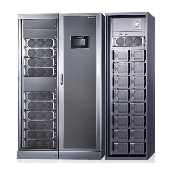
Figure 2-8 UPS appearance (1) Power Unit 1 (2) Power Unit 2 (3) Power Unit 3 (4) Bypass Unit (5) Input and output Unit 1 (6) Input and output Unit 2 Issue 04 (2020-03-03) Copyright © Huawei Technologies Co., Ltd. -
Page 31: Product Structure
(10) Output circuit (11) Output circuit (12) Input circuit breaker of power breaker of power breaker of power breaker of power unit unit 1 (Q1-1) unit 1 (Q5-1) unit 3 (Q5-3) 3 (Q1-3) Issue 04 (2020-03-03) Copyright © Huawei Technologies Co., Ltd. -
Page 32: Power Module
0.2 Hz, on for 2.5s and off for 2.5s). Blinking at short The module is not configured, the intervals inverter or rectifier DSP software is being upgraded, or the inverter FPGA software is being upgraded (blinking at 4 Issue 04 (2020-03-03) Copyright © Huawei Technologies Co., Ltd. - Page 33 Specifications Dimensions (H x W x D): 130 mm x 442 mm x 620 mm Weight: < 34 kg Rated output capacity: 55 kVA/55 kW Issue 04 (2020-03-03) Copyright © Huawei Technologies Co., Ltd.
-
Page 34: Bypass Module
Blinking at short The bypass is not configured or the intervals DSP software is being upgraded (blinking at 4 Hz, on for 0.125s and off for 0.125s). The bypass CPLD software is being Issue 04 (2020-03-03) Copyright © Huawei Technologies Co., Ltd. - Page 35 Bypass module: 263.5 mm x 642 mm x 668 mm − Bypass control module: 86.1 mm x 642 mm x 600 mm Weight: − Bypass module: < 90 kg Bypass control module: < 16 kg − Issue 04 (2020-03-03) Copyright © Huawei Technologies Co., Ltd.
-
Page 36: Monitoring Module
(10) Dry contact card (11) Dry (12) MDU port contacts (13) RS485 port (14) Fast Ethernet (FE) (15) COM2 (16) COM1 port port port (17) Battery temperature (18) Optional card sensor port subrack cover Issue 04 (2020-03-03) Copyright © Huawei Technologies Co., Ltd. -
Page 37: Ecm
Green Steady on This ECM is the active ECM. Blinking at 0.5 This ECM is the standby ECM and it is ready. This ECM is not ready or the CPLD of Issue 04 (2020-03-03) Copyright © Huawei Technologies Co., Ltd. -
Page 38: Dry Contact Card
2.3.5.1.3 Dry Contact Card Appearance Figure 2-15 Dry contact card Table 2-6 Functions of control signal ports on the dry contact card Silk Screen Control Control Description Status Initial Status Module 1 Module 2 Issue 04 (2020-03-03) Copyright © Huawei Technologies Co., Ltd. - Page 39 EPO_12V +12 V disconnected from the EPO_12V port, EPO is triggered. SWITCH Port for Connected: circuit Connected breaker ON STATUS_OU monitoring the UPS output Disconnected: circuit breaker circuit breaker Issue 04 (2020-03-03) Copyright © Huawei Technologies Co., Ltd.
- Page 40 The dry contact card allows the UPS to detect and manage the switch status of the battery system (including the external battery switch) and implement remote emergency power-off (EPO). Specifications Hot-swappable 0.5 U high Issue 04 (2020-03-03) Copyright © Huawei Technologies Co., Ltd.
-
Page 41: Monitoring Interface Card
DO_3 DO_3 is used to output alarms and indicates bypass mode by default. It can be set to indicate critical alarms, minor Issue 04 (2020-03-03) Copyright © Huawei Technologies Co., Ltd. - Page 42 Signal cables must be double-insulated twisted cables. If the cable length is 25–50 m, the cross-sectional area must be 0.5–1.5 mm RS485 cables must be shielded cables. Figure 2-17 and Figure 2-18 are recommended wiring methods for DO ports. Issue 04 (2020-03-03) Copyright © Huawei Technologies Co., Ltd.
- Page 43 UPS5000-S-1600 kVA User Manual 2 Overview Figure 2-17 Wiring method 1 Figure 2-18 Wiring method 2 Figure 2-19 COM1 pins Table 2-8 COM1 pin definition Description RS485– RS485+ Issue 04 (2020-03-03) Copyright © Huawei Technologies Co., Ltd.
- Page 44 Connect pins 1, 2, 4, and 5. Twist cables to pin 1 and pin 4 into one cable and then connect it to RS485+. Twist cables to pin 2 and pin 5 into one cable and then connect it to RS485–. Issue 04 (2020-03-03) Copyright © Huawei Technologies Co., Ltd.
-
Page 45: Intelligent Detection Board
The indicator is steady on after the board is powered on and does not need to be controlled by the CPU. Indicates that the intelligent detection board is powered off. Issue 04 (2020-03-03) Copyright © Huawei Technologies Co., Ltd. - Page 46 0.5 mm to 1.5 mm FE cables are shielded cables. Figure 2-22 COM_OUT port pins Table 2-12 COM_OUT port pin definitions Pin No. Description RS485+ RS485- RS485+ RS485- CANH CANL Issue 04 (2020-03-03) Copyright © Huawei Technologies Co., Ltd.
- Page 47 Boolean values inside the cabinet, communicates with the monitoring display unit (MDU) and other intelligent detection boards, and controls indicators. Specifications Hot-swappable 1 U high Issue 04 (2020-03-03) Copyright © Huawei Technologies Co., Ltd.
-
Page 48: Dry Contact Extended Card
DO_2 Indicates relay output signals. The dry contact is normally open by default. When the preset status occurs, the relay is closed. Users can set the dry Issue 04 (2020-03-03) Copyright © Huawei Technologies Co., Ltd. - Page 49 Input DI_1 Reserved DI_2 Reserved DI_3 Reserved DI_4 Reserved DI_5 Reserved The following two methods are recommended for connecting cables to DO ports on the dry contact extended card. Issue 04 (2020-03-03) Copyright © Huawei Technologies Co., Ltd.
-
Page 50: Backfeed Protection Card
2.3.5.4 Backfeed Protection Card Appearance Figure 2-27 Backfeed protection card Functions When a backfeed occurs, the backfeed protection card sends signals to trigger alarm signals or quickly disconnects the feedback loop. Issue 04 (2020-03-03) Copyright © Huawei Technologies Co., Ltd. - Page 51 NC and COM are normally closed contacts. When a backfeed occurs, the normally BFP_NC open contacts are closed and the normally closed contacts are open. RSV_NO Reserved (reserved) RSV_COM RSV_NC Issue 04 (2020-03-03) Copyright © Huawei Technologies Co., Ltd.
- Page 52 The backfeed protection card needs to be powered by the UPS output or a more reliable third-party power to ensure that the backfeed protection card can isolate faults if backfeed faults occur in battery mode. Specifications The backfeed protection card is hot-swappable. Issue 04 (2020-03-03) Copyright © Huawei Technologies Co., Ltd.
-
Page 53: Mdu
The UPS is running properly or a warning has been generated. The MDU is powered off. The indicator on the MDU panel is yellow when the bypass supplies power in non-ECO mode. Issue 04 (2020-03-03) Copyright © Huawei Technologies Co., Ltd. - Page 54 View or obtain UPS running information during preventive maintenance. NOTE Only Huawei service engineers or authorized service engineers are allowed to use the WiFi module. To ensure security, remove the WiFi module immediately after use. ...
-
Page 55: Typical Configurations
(STS) can be installed to start the bus synchronization controller (BSC). The UPS systems work in normal mode or bypass mode. The conceptual diagram uses a dual-bus system with a single UPS as an example. Issue 04 (2020-03-03) Copyright © Huawei Technologies Co., Ltd. -
Page 56: Optional Components
PDU8000-(0630, 1250, 2000) -BGA001 multiple battery strings. DCV8-BGA001 BBB Box User Manual PDU8000-2000DCV8 -BGA001 Ambient Monitors the ambient UPS Ambient Temperature temperature and temperature and humidity, and and Humidity Sensor User Issue 04 (2020-03-03) Copyright © Huawei Technologies Co., Ltd. - Page 57 Fan unit The fan unit is used for top air UPS5000-S-1600 kVA User exhaust. Manual BSC cable 5 m/10 m/15 m/60 m Connects UPSs in parallel. Issue 04 (2020-03-03) Copyright © Huawei Technologies Co., Ltd.
-
Page 58: Installation
The optimal operating temperatures for valve-regulated lead-acid batteries (VRLA batteries) are 20–30° C. Operating temperatures higher than 30° C shorten the battery lifespan and operating temperatures lower than 20° C reduce the battery backup time. Issue 04 (2020-03-03) Copyright © Huawei Technologies Co., Ltd. -
Page 59: Installation Clearances
Insulate installation tools to prevent electric shocks. Prepare the following tools and meters indicated in Table 3-1 for installation. Table 3-1 Tools and meters Tools and Meters Electric pallet truck Manual pallet truck Ladder Rubber mallet Issue 04 (2020-03-03) Copyright © Huawei Technologies Co., Ltd. - Page 60 Level instrument Polyvinyl chloride Cotton cloth Label Electrician's knife (PVC) insulation tape Electrostatic Protective gloves Insulated gloves Insulation protective shoes discharge (ESD) gloves Torque screwdriver Cable cutter Brush Flat-head screwdriver (2–5 mm) Issue 04 (2020-03-03) Copyright © Huawei Technologies Co., Ltd.
-
Page 61: Preparing Power Cables And Copper Bars
3.1.3 Preparing Power Cables and Copper Bars The UPS can generate large leakage currents. A circuit breaker that provides leakage current protection is not recommended. Prepare wiring copper bars based on the following figures and current requirements. Issue 04 (2020-03-03) Copyright © Huawei Technologies Co., Ltd. - Page 62 User Manual 3 Installation Figure 3-2 Distances between the top copper bars of the bypass unit and input and output unit (unit: mm) Figure 3-3 Distances between top copper bars (unit: mm) Issue 04 (2020-03-03) Copyright © Huawei Technologies Co., Ltd.
- Page 63 When selecting, connecting, and routing power cables, follow local safety regulations and rules. When the external conditions change, for example, the cable layout or ambient temperatures, perform verification in accordance with the IEC-60364-5-52 or the local regulations. Issue 04 (2020-03-03) Copyright © Huawei Technologies Co., Ltd.
- Page 64 Crimped DT terminals 35 mm 47 N· m Equipotential Crimped DT terminals 4.5 N· m ground point Table 3-4 Recommended upstream input and downstream output circuit breakers Circuit Breaker Name Specifications Issue 04 (2020-03-03) Copyright © Huawei Technologies Co., Ltd.
-
Page 65: Unpacking
Step 1 Use a pallet truck to transport the UPS to the installation position. Step 2 Remove the UPS outer packing. Step 3 Remove the bolts that secure the UPS to the pallet and remove the UPS from the pallet. Issue 04 (2020-03-03) Copyright © Huawei Technologies Co., Ltd. -
Page 66: Single Ups Installation
During delivery, the power units and bypass unit are transported separately, and two input/output units are transported together. Procedure Step 1 Determine the cabinet installation positions on the floor based on holes in the marking-off template for floor installation. Issue 04 (2020-03-03) Copyright © Huawei Technologies Co., Ltd. - Page 67 Figure 3-7 Dimensions for the holes for the bypass unit and input/output unit (unit: mm) Step 2 Use a hammer drill to drill holes for installing the expansion bolts and then install the expansion sleeves in the holes. Issue 04 (2020-03-03) Copyright © Huawei Technologies Co., Ltd.
- Page 68 Partially tighten the expansion bolt and vertically insert it into the hole. Hit the expansion bolt using a rubber mallet until the expansion sleeve is fully inserted into the hole. Partially tighten the expansion bolt. Remove the bolt, spring washer, and flat washer. Issue 04 (2020-03-03) Copyright © Huawei Technologies Co., Ltd.
-
Page 69: Channel Steel Installation
Step 6 Use M12x60 expansion bolts to secure the power units, bypass unit, and input/output units to the expansion bolt mounting holes on the floor in sequence. Step 7 Install anchor baffle plates. Figure 3-11 Installing anchor baffle plates ----End 3.2.1.2 Channel Steel Installation Prerequisites Issue 04 (2020-03-03) Copyright © Huawei Technologies Co., Ltd. - Page 70 UPS5000-S-1600 kVA User Manual 3 Installation Huawei does not provide channel steel or expansion bolts used for securing channel steel. Ensure that the surface of channel steels is smooth. Figure 3-12 Recommended channel steel dimensions (unit: mm) Procedure Step 1 Determine the cabinet installation positions on the channel steel based on holes in the marking-off template for channel steel installation.
-
Page 71: Installing Busbars
1 unit and power unit 3. Figure 3-14 Removing front panels and dustproof covers Step 2 Install the U-shaped sealing plate component (numbered 01). Issue 04 (2020-03-03) Copyright © Huawei Technologies Co., Ltd. - Page 72 Figure 3-16 Installing busbar component Step 4 Use copper bars (numbered 04–06) to connect the busbar components (numbered 02 and 03). Before installation, remove the screws that are partially tightened from the busbar component. Issue 04 (2020-03-03) Copyright © Huawei Technologies Co., Ltd.
- Page 73 (1) Insulator (The two insulators do not need to be secured with screws.) Step 5 Install the busbar component (numbered 07) and secure it to the cabinet. Figure 3-18 Installing busbar component Step 6 Install the left sealing plate (numbered 08). Issue 04 (2020-03-03) Copyright © Huawei Technologies Co., Ltd.
- Page 74 Step 7 Install the side sealing plate (numbered 09) for the input and output unit. Figure 3-20 Installing sealing plates Step 8 Install the side sealing plate (numbered 10) for power unit 3. Issue 04 (2020-03-03) Copyright © Huawei Technologies Co., Ltd.
- Page 75 Step 9 Install the rear sealing plate (numbered 11) for the power unit 1 and power unit 2. Figure 3-22 Installing sealing plates Step 10 Install the sealing plates (numbered 12) for the bypass unit and input and output unit. Issue 04 (2020-03-03) Copyright © Huawei Technologies Co., Ltd.
- Page 76 Step 11 Install the sealing plates (numbered 13) for power unit 3. Figure 3-24 Installing sealing plates Step 12 Install the busbar (numbered 14) for power unit 3. Figure 3-25 Installing the busbar component Issue 04 (2020-03-03) Copyright © Huawei Technologies Co., Ltd.
- Page 77 Step 14 Install the right sealing plate (numbered 17) for power unit 3. Figure 3-27 Installing sealing plates Step 15 Install supports for the busbar covers. Figure 3-28 Installing supports for the busbar covers Issue 04 (2020-03-03) Copyright © Huawei Technologies Co., Ltd.
- Page 78 (4) Input and output unit 1 plate (5) Input and output unit 2 plate (6) Power unit 3 plate Step 18 Install the busbar covers. Figure 3-31 Installing the busbar covers Issue 04 (2020-03-03) Copyright © Huawei Technologies Co., Ltd.
-
Page 79: Ups Cable Connection Reference
Choose an appropriate cabling route based on the actual situation. The figure is for reference only. Step 4 Connect the cable with a crimped terminal to the corresponding copper bar. Step 5 Clean foreign matter inside the cabinet. Issue 04 (2020-03-03) Copyright © Huawei Technologies Co., Ltd. -
Page 80: Connecting Cables
Step 1 Connect the equipotential ground point and the ground bar in the equipment room. Step 2 Connect the copper bars between the mains input and bypass input (N and PE copper bars). Issue 04 (2020-03-03) Copyright © Huawei Technologies Co., Ltd. - Page 81 (L1, L2, and L3 copper bars) between the mains input and bypass input. Figure 3-35 Installing the copper bars Step 4 Install the U, V, and W copper bars. Issue 04 (2020-03-03) Copyright © Huawei Technologies Co., Ltd.
- Page 82 Step 5 Connect input and output busbars and battery cables based on the top copper bar position diagram. Step 6 Install supports and covers on the top of the protective covers for each power unit. Figure 3-37 Installing top supports and covers Issue 04 (2020-03-03) Copyright © Huawei Technologies Co., Ltd.
- Page 83 Power unit 2 terminal reserved in the cabinet) Power unit 3 BP-XS3 Input and output unit 2 BP-XS4 (bound to input and output unit 1) Input and output unit 1 BP-XS5 Issue 04 (2020-03-03) Copyright © Huawei Technologies Co., Ltd.
-
Page 84: Installing Optional Components
3.3 Installing Optional Components 3.3.1 Installing a Battery Grounding Failure Detector Prerequisites If the power units share battery strings, you need to install a battery grounding failure detector only in power unit 1. Issue 04 (2020-03-03) Copyright © Huawei Technologies Co., Ltd. - Page 85 Step 3 Remove the front panel from the SPD in the bypass unit. Step 4 Connect cables. Connect the power cables of the battery grounding failure detector to copper bars U and N on the top of each power unit cabinet. Issue 04 (2020-03-03) Copyright © Huawei Technologies Co., Ltd.
- Page 86 Connect the signal cables of the battery grounding failure detectors in power units 1 and 2 to the wiring terminal on the beam where the SPD is installed in the bypass unit. Issue 04 (2020-03-03) Copyright © Huawei Technologies Co., Ltd.
-
Page 87: Installing A Fan Unit
Step 5 Reinstall the top cover for each power unit and the front panel for the SPD in the bypass unit. ----End 3.3.2 Installing a Fan Unit Configure the fan unit if you install the cabinet against the wall. Issue 04 (2020-03-03) Copyright © Huawei Technologies Co., Ltd. - Page 88 (8) Fan unit – right (5) Input/output unit 1 (6) Input/output unit 2 (7) Power unit 3 Figure 3-47 Fan unit structure (1) Fan power switch (2) Cover stopper (3) Cover Issue 04 (2020-03-03) Copyright © Huawei Technologies Co., Ltd.
- Page 89 A: mounting holes on the channel steel B: mounting holes on the floor Figure 3-48 Fan unit hole dimensions (unit: mm) Figure 3-49 Power unit 1 hole dimensions (unit: mm) Issue 04 (2020-03-03) Copyright © Huawei Technologies Co., Ltd.
- Page 90 UPS5000-S-1600 kVA User Manual 3 Installation Figure 3-50 Power unit 2 hole dimensions (unit: mm) Figure 3-51 Bypass unit hole dimensions (unit: mm) Issue 04 (2020-03-03) Copyright © Huawei Technologies Co., Ltd.
- Page 91 Step 4 Remove the rear door from the cabinet. Step 5 Remove the door header from the rear of the cabinet. Figure 3-54 Removing the door header (rear view of the cabinet) Issue 04 (2020-03-03) Copyright © Huawei Technologies Co., Ltd.
- Page 92 Combine input and output unit and the bypass unit. (Install anchor screws close to the wall, install connecting kits at the bottom, top, and then middle of the cabinet, and secure the anchor screws under the front door of the cabinet.) Issue 04 (2020-03-03) Copyright © Huawei Technologies Co., Ltd.
- Page 93 Combine power unit. (Install anchor screws close to the wall, install connecting kits at the bottom, top, and then middle of the cabinet, and secure the anchor screws under the front door of the cabinet.) Issue 04 (2020-03-03) Copyright © Huawei Technologies Co., Ltd.
- Page 94 Remove the bottom cover from the fan unit. Tighten the anchor screws. Reinstall the bottom cover. Figure 3-59 Combining fan units (1) Connecting kits without floating nuts (2) Connecting kits with floating nuts Issue 04 (2020-03-03) Copyright © Huawei Technologies Co., Ltd.
- Page 95 Figure 3-61 Installing the rear sealing plate of the power unit Step 3 Install the fan baffle plate (numbered 50). ((Power units 1 is used as an example. The installation procedure for power unit 3 is the same.) Issue 04 (2020-03-03) Copyright © Huawei Technologies Co., Ltd.
- Page 96 Step 5 Install the front and rear sealing plates (numbered 12) for the bypass unit and input and output unit 1. Install the front and rear sealing plates (numbered 15 and 16) for input and output unit Issue 04 (2020-03-03) Copyright © Huawei Technologies Co., Ltd.
- Page 97 The procedure for installing a cable for the fan unit and installing a mounting plate is different. For details about how to install cables for the power cabinet, bypass cabinet, and input/output bypass cabinet, see the preceding steps. Step 1 Install the cable of the fan unit. Issue 04 (2020-03-03) Copyright © Huawei Technologies Co., Ltd.
- Page 98 (6) Input/Output unit 1 (7) Input/Output unit 2 (8) Power unit 3 mounting plate mounting plate mounting plate mounting plate (9) Fan unit – right (10) Right mounting mounting plate plate Issue 04 (2020-03-03) Copyright © Huawei Technologies Co., Ltd.
-
Page 99: Connecting Other Optional Components
When the address ranges from 16 to 30, the ambient temperature and humidity sensor is used as a battery temperature sensor. Table 3-9 DIP switch address mapping 1 (battery temperature sensor) Toggle Switch Issue 04 (2020-03-03) Copyright © Huawei Technologies Co., Ltd. -
Page 100: Remote Epo
Switch 3.4 Remote EPO Huawei does not provide the EPO switch or cable. If the cable is required, the recommended cable is 22 AWG. Equip the EPO switch with a protective cover to prevent misoperations, and cover the cable with protective tubing. -
Page 101: Parallel System Installation
3.5 Parallel System Installation 3.5.1 Connecting Power Cables Procedure Step 1 Ground each UPS in a parallel system separately, and connect power cables and battery cables. Step 2 Connect cables to the parallel system. Issue 04 (2020-03-03) Copyright © Huawei Technologies Co., Ltd. -
Page 102: Connecting Signal Cables
The power cables include bypass input power cables and UPS output power cables. Figure 3-70 Single UPS dual-bus system schematic diagram ----End 3.5.2 Connecting Signal Cables Connecting Signal Cables to a Parallel System Issue 04 (2020-03-03) Copyright © Huawei Technologies Co., Ltd. -
Page 103: Installation Verification
Layout of the busway The busway and cables are routed properly as required and cables by the customer. Labels on the busway Both ends of a busway and cable are labeled. Labels are Issue 04 (2020-03-03) Copyright © Huawei Technologies Co., Ltd. - Page 104 2. After verifying the installation, reinstall all the covers. 3. Do not remove the dustproof cover before power-on to prevent dust inside the UPS. Issue 04 (2020-03-03) Copyright © Huawei Technologies Co., Ltd.
-
Page 105: User Interface
Figure 4-1 Main menu Table 4-1 Main screen description Number Area Function Status bar Displays the UPS model, capacity, configuration, current date and time, USB flash drive status, and buzzer status. Issue 04 (2020-03-03) Copyright © Huawei Technologies Co., Ltd. - Page 106 On the System Info screen of the system, you can tap the power unit or bypass unit as indicated in the following figure to access the monitoring screen for the power unit or bypass unit. Issue 04 (2020-03-03) Copyright © Huawei Technologies Co., Ltd.
-
Page 107: Menu Hierarchy
System Info Runn Info AC Output UPS Load Mains Input Bypass Input Power Unit 1 Batt. Power Unit 2 Batt. Power Unit 3 Batt. Total Runtime Environment Data Intelli Temp Detect Issue 04 (2020-03-03) Copyright © Huawei Technologies Co., Ltd. - Page 108 Parameter Sync DST Settings Maintenance USB Operations Inv. ON Inv. OFF ECM Switchover Screen Calib. About Common Functions AC Output UPS Load Mains Input Inv. ON Inv. OFF Buzzer Off Historical Alarms Issue 04 (2020-03-03) Copyright © Huawei Technologies Co., Ltd.
- Page 109 About Common Functions AC Output UPS Load Mains Input Historical Alarms Bypass Unit Bypass Unit Status Bypass Load Bypass Unit Info Runn Info AC Output UPS Load Bypass Input Total Runtime Issue 04 (2020-03-03) Copyright © Huawei Technologies Co., Ltd.
-
Page 110: System Info
Power Unit 3 Batt. Power unit 3 battery data Total Runtime System inverter and Inverter runtime of System bypass bypass runtime this power unit runtime Environment Data System environment data Battery Information Battery information Issue 04 (2020-03-03) Copyright © Huawei Technologies Co., Ltd. - Page 111 Circuit Breaker Mains input and Status system output switch status On the System Info screen, tap to access the Runn Info screen of the system. Figure 4-3 System running 1 Issue 04 (2020-03-03) Copyright © Huawei Technologies Co., Ltd.
- Page 112 On the System Info screen, tap the power unit icon to access the Power Unit N battery screen, and tap to access the Runn Info screen of the current power unit. Figure 4-5 Power unit running 1 Figure 4-6 Power unit running 2 Issue 04 (2020-03-03) Copyright © Huawei Technologies Co., Ltd.
- Page 113 Mains input line voltage Phase current (A) Mains input phase current Frequency (Hz) Mains input frequency Power factor Proportion of the mains input active power to the mains input apparent power. Issue 04 (2020-03-03) Copyright © Huawei Technologies Co., Ltd.
- Page 114 If the value is less than 1, the value takes 0. If the value is greater than or equal to 1 and less than 2, the value takes 1. Issue 04 (2020-03-03) Copyright © Huawei Technologies Co., Ltd.
-
Page 115: Alarms
Module Data: reflects each data of a module. 4.1.3.2 Alarms Table 4-15 Alarm display description Running Item System Power Unit Bypass Unit Active Alarms All active alarms Active alarms of this Active alarms of the Issue 04 (2020-03-03) Copyright © Huawei Technologies Co., Ltd. - Page 116 System Info screen to access the Alarms screen. Figure 4-7 System alarms Active Alarms This screen displays alarm information including the severity, name, ID, location, and generation time. Figure 4-8 Active alarms Issue 04 (2020-03-03) Copyright © Huawei Technologies Co., Ltd.
-
Page 117: Settings
Comm - Amb T/H Sensor Ambient temperature and humidity sensor settings of the system Comm - Batt Temp Sensor Battery temperature sensor settings Comm - WiFi Settings System WiFi settings Issue 04 (2020-03-03) Copyright © Huawei Technologies Co., Ltd. - Page 118 Synchronizing parameters of the power units and bypass unit. DST Settings DST settings On the System Info screen, tap to access the Settings screen of the system. Figure 4-10 System settings 1 Issue 04 (2020-03-03) Copyright © Huawei Technologies Co., Ltd.
- Page 119 On the System Info screen, tap the power unit icon to access the Power Cabinet N Info screen, and tap to display the Settings screen of the current power unit. Figure 4-12 Power unit settings Issue 04 (2020-03-03) Copyright © Huawei Technologies Co., Ltd.
- Page 120 UPS5000-S-1600 kVA User Manual 4 User Interface Communication Settings Figure 4-13 System communication settings Figure 4-14 Power unit communication settings Figure 4-15 IP settings IP address allocation Issue 04 (2020-03-03) Copyright © Huawei Technologies Co., Ltd.
- Page 121 Specifies the subnet mask of the 255.255.255.0 0.0.0.0–255.255. Ethernet. 255.255 Gateway Specifies the Ethernet gateway. 192.168.0.1 1.0.0.0–223.255. 255.255 NAT mapping NAT means network address Disable Disable, Enable translation. If it is set to Disable, Issue 04 (2020-03-03) Copyright © Huawei Technologies Co., Ltd.
- Page 122 Stop bit in the Modbus 1–2 communication frame format. When the UPS is connected over the serial port Modbus, set this parameter based on the frame format that the upstream device Modbus supports. Issue 04 (2020-03-03) Copyright © Huawei Technologies Co., Ltd.
- Page 123 Figure 4-18 Ambient temperature and humidity sensor Item Description Default Value Value Range Start address 32–44 Quantity Number of cascaded ambient 0–4 temperature and humidity sensors Issue 04 (2020-03-03) Copyright © Huawei Technologies Co., Ltd.
- Page 124 SSID after connecting a WiFi characters of the module over a USB port to MAC address identify the WiFi device to which the mobile phone is connected. Password The password for accessing Changeme WiFi. Issue 04 (2020-03-03) Copyright © Huawei Technologies Co., Ltd.
- Page 125 ± 8%, ± 9%, ± 10% voltage and the rated voltage is greater than this value, the system determines that the ECO voltage is abnormal and transfers Issue 04 (2020-03-03) Copyright © Huawei Technologies Co., Ltd.
- Page 126 In start delay (s) the case of battery undervoltage, the system automatically shortens the delay for transferring to normal mode to 1/8 of the normal Issue 04 (2020-03-03) Copyright © Huawei Technologies Co., Ltd.
- Page 127 Figure 4-23 Input settings Item Description Default Value Value Range D.G. mode Set this parameter to Enable Disable Disable, Enable when a D.G. connects to the input PDC. The UPS enters the Issue 04 (2020-03-03) Copyright © Huawei Technologies Co., Ltd.
- Page 128 (If the voltage level is 380 V or 400 V, the default upper limit is +15%. If the voltage level is 415 V, the default upper limit is +10%.) Issue 04 (2020-03-03) Copyright © Huawei Technologies Co., Ltd.
- Page 129 (Hz/s) is fast, the inverter frequency is unstable. Bypass Settings Figure 4-25 Bypass settings Item Description Default Value Value Range Maximum When the difference between the When the voltage level is 380 V, Issue 04 (2020-03-03) Copyright © Huawei Technologies Co., Ltd.
- Page 130 ECO frequency range. Battery Settings Battery parameter settings impact battery maintenance, battery lifespan, and UPS discharge time. When you set battery parameters, note the following: Issue 04 (2020-03-03) Copyright © Huawei Technologies Co., Ltd.
- Page 131 2 V. A battery is a module consisting of single or multiple cells in a shell. Each battery has a nominal voltage of 2 V, 6 V, or 12 V. Figure 4-26 Battery settings 1 Figure 4-27 Battery settings 2 Issue 04 (2020-03-03) Copyright © Huawei Technologies Co., Ltd.
- Page 132 Chg. cur. The charging current limit is a 0.1C10 0.05C10 to multiple of the battery capacity. 0.15C10 limiting coef. (C10) Cell float Specifies the battery float 2.25 V/cell 2.23 V/cell to Issue 04 (2020-03-03) Copyright © Huawei Technologies Co., Ltd.
- Page 133 30–90 dis. test interval discharge test. Shallow dis. Set the proportion of the 10%–50% test dis. ratio discharge capacity to the total discharge capacity. The value is configurable in any mode. Issue 04 (2020-03-03) Copyright © Huawei Technologies Co., Ltd.
- Page 134 Enable or disable PDC maintenance breaker [MT] circuit breaker status detection. BP/SYSMT switch If the BP/SYSMT switch is set to Enable, the port has dry contact signal access. Using the port depends on the Issue 04 (2020-03-03) Copyright © Huawei Technologies Co., Ltd.
- Page 135 DO on the MUE07A DO_3, MUE07A. MUE07A DO_4, MUE07A DO_5 MUE07A DI_1, Corresponds to the signal of the input MUE07A DI_2, dry contact DI on the MUE07A. MUE07A DI_3, Issue 04 (2020-03-03) Copyright © Huawei Technologies Co., Ltd.
- Page 136 Figure 4-29 User settings 1 Figure 4-30 User settings 2 Item Description Default Value Value Range Language Twelve languages are supported English English, Chinese, Spanish, Dutch, French, German, Italian, Polish, Portuguese, Russian, Swedish, Issue 04 (2020-03-03) Copyright © Huawei Technologies Co., Ltd.
-
Page 137: Maintenance
UPS Inv. OFF Shutting down the inverter of the single ECM Switchover Switchover of active and standby ECMs Screen Calib. Calibrating the touchscreen Battery Maint. Battery maintenance of this power unit Issue 04 (2020-03-03) Copyright © Huawei Technologies Co., Ltd. - Page 138 Figure 4-32 Power unit maintenance Choose Monitoring > Param. Settings > System Settings on the WebUI, if the Bus capa. life is set to Enable, the Maintenance is displayed on the Bus Capa. Life screen. Issue 04 (2020-03-03) Copyright © Huawei Technologies Co., Ltd.
- Page 139 UPS reliability. Battery maintenance includes Forced Equalized Charging, Shallow Dis. Test, and Capacity Test. The next maintenance time displayed on the screen indicates the upcoming time in which to check batteries. Issue 04 (2020-03-03) Copyright © Huawei Technologies Co., Ltd.
- Page 140 Bus capacitor life forecast If the service life of a capacitor is about to end, that is, Module X bus capacitor life (y) is less than 1.0, contact Huawei technical support to replace the power module. Issue 04 (2020-03-03) Copyright © Huawei Technologies Co., Ltd.
-
Page 141: About
4.1.4 System Status On the System Status screen, you can view the data and information related to the mains input, bypass input, load, and battery by tapping corresponding icons. Figure 4-36 System status Issue 04 (2020-03-03) Copyright © Huawei Technologies Co., Ltd. -
Page 142: Common Functions
Mains Input System mains input Mains input data of data this power unit Inv. ON Starting the inverter of the single UPS Inv. OFF Shutting down the inverter of the single Issue 04 (2020-03-03) Copyright © Huawei Technologies Co., Ltd. -
Page 143: Webui
Step 1 Open the browser and choose Tools > Internet Options. Step 2 On the Advanced tab page, ensure that Use TLS 1.0, and Use TLS 1.1 are selected and click Figure 4-39 Settings in the Internet Options dialog box Issue 04 (2020-03-03) Copyright © Huawei Technologies Co., Ltd. - Page 144 After a user logs in to the WebUI, if another user logs in with the same user name, the current account will be logged out. It is advised to change the password after the first login using User Mgmt. on the Config. page to prevent unauthorized access. ----End Issue 04 (2020-03-03) Copyright © Huawei Technologies Co., Ltd.
-
Page 145: Monitoring Page
The Active Alarms page is displayed by default. Information Displays system monitoring information. area The parameters that have been introduced in the LCD section are not described in the WebUI section. Issue 04 (2020-03-03) Copyright © Huawei Technologies Co., Ltd. -
Page 146: Parameter Settings
EPO is performed only when this parameter is enabled and the EPO switch is triggered. When EPO detection is changed from Disable to Enable, check that the EPO cable is connected correctly. Issue 04 (2020-03-03) Copyright © Huawei Technologies Co., Ltd. - Page 147 The default value is 0 ms, which means that the data during 20 ms before the fault occurs is recorded. If the value is set to 40 ms, it means Issue 04 (2020-03-03) Copyright © Huawei Technologies Co., Ltd.
- Page 148 The interruption for the UPS to 0 ms, 40 ms, 60 interruption transfer from inverter mode to ms, 80 ms, 100 transfer time bypass mode is 0–2 ms, and from ms, 120 ms Issue 04 (2020-03-03) Copyright © Huawei Technologies Co., Ltd.
- Page 149 Bus overvolt. If Bus overvoltage recovery is 5s, 1min, 5min, recovery time set to Enable, the bus 10min overvoltage alarm is automatically cleared, and the Issue 04 (2020-03-03) Copyright © Huawei Technologies Co., Ltd.
- Page 150 ECO mode. If this parameter is set to Enable, the preceding detection is not performed. Whether the bypass current is imbalanced does not affect the ECO bypass mode. Battery Settings Issue 04 (2020-03-03) Copyright © Huawei Technologies Co., Ltd.
- Page 151 If the SOC is lower than the 0–100 equalized specified value, batteries start charging (%) equalized charging. Scheduled After batteries transfer from 30–180 equalized equalized charging to float charging charging, if the batteries do not Issue 04 (2020-03-03) Copyright © Huawei Technologies Co., Ltd.
- Page 152 When a value exceeds deviation alarm the specified range, an alarm is thres. (%) generated. The calculation formula is (Charge/Discharge voltage – Average voltage)/Average voltage x 100%. Issue 04 (2020-03-03) Copyright © Huawei Technologies Co., Ltd.
-
Page 153: Communication Settings
Batt. Volt. Below Threshold, dry contact and the battery voltage is lower (V/cell) than this threshold, the output dry contact will output signals. 4.2.2.2 Communication Settings Figure 4-43 System communication settings Issue 04 (2020-03-03) Copyright © Huawei Technologies Co., Ltd. -
Page 154: Control
Table 4-22 Query description Cabinet Historical Records System Query all historical alarms. Power unit Query historical alarms of the current power unit. Bypass unit Query historical alarms of the bypass unit. Issue 04 (2020-03-03) Copyright © Huawei Technologies Co., Ltd. -
Page 155: Logs
Query and export the battery test logs of the current power unit. Bypass unit Figure 4-48 Logs 4.2.4 Config. 4.2.4.1 User Management On the home page, choose Config. > User Mgmt. Issue 04 (2020-03-03) Copyright © Huawei Technologies Co., Ltd. -
Page 156: Site Config
If the password complexity check is enabled, the user password is required to be a string of 6–20 characters and contain at least two types of characters. 4.2.4.2 Site Config. On the home page, choose Config. > Site Config. Issue 04 (2020-03-03) Copyright © Huawei Technologies Co., Ltd. - Page 157 Test to check whether the test email can be received. Configure Alarm Notification Server is used to configure a server for receiving alarm emails from the monitoring system. Issue 04 (2020-03-03) Copyright © Huawei Technologies Co., Ltd.
-
Page 158: Rccmd
Enable upon first login. After you submit the setting, the page refreshes. The controls such as SSL Encrypted Transmission and Event Configuration will be displayed on the page, as shown in Figure 4-52. Figure 4-51 RCCMD function disabled Issue 04 (2020-03-03) Copyright © Huawei Technologies Co., Ltd. - Page 159 Disable, the RCCMD certificate controls will not be displayed on the page, as shown in Figure 4-54. If SSL Encrypted Transmission is set to Disable, a message indicating there is a risk will be displayed. Issue 04 (2020-03-03) Copyright © Huawei Technologies Co., Ltd.
- Page 160 The MDU supports 17 alarm events, and a maximum of 50 jobs can be added for each event, as shown in Figure 4-55. Figure 4-55 shows the buttons on the Event Configuration page, and Table 4-24 describes these buttons. Issue 04 (2020-03-03) Copyright © Huawei Technologies Co., Ltd.
- Page 161 Button for deleting all jobs You can delete all jobs of the event by clicking this button. Figure 4-56 shows the buttons after one event is expanded and Table 4-25 describes these buttons. Issue 04 (2020-03-03) Copyright © Huawei Technologies Co., Ltd.
- Page 162 RCCMD Shutdown: You need to specify the RCCMD client IP address and port. When the RCCMD client receives the job, it will shut down the computer. Issue 04 (2020-03-03) Copyright © Huawei Technologies Co., Ltd.
- Page 163 RCCMD Execute: Specify the RCCMD client IP address, port, and command to be executed. For example, enter SHUTDOWN, and the RCCMD client will shut down the computer after receiving the command. Issue 04 (2020-03-03) Copyright © Huawei Technologies Co., Ltd.
- Page 164 UPS input voltage value (for example, single-phase: 220 V; three-phase A: 220 V, B: 220 V, C: 220 V). Table 4-26 lists the signal names that can be entered. Figure 4-60 RCCMD TRAP Issue 04 (2020-03-03) Copyright © Huawei Technologies Co., Ltd.
- Page 165 RCCMD client once. At X seconds remaining time: When the battery backup time has only X seconds left, the job will be sent to the RCCMD client once. Issue 04 (2020-03-03) Copyright © Huawei Technologies Co., Ltd.
-
Page 166: Managing The Ups By Using The Nms Complying With Rfc1628 Standard
The MIB is in the MDU. Click Download UPS-RFC1628-MIB on the page of the web browser to download the MIB file which allows the third-party NMS to manage the UPS remotely. Issue 04 (2020-03-03) Copyright © Huawei Technologies Co., Ltd. - Page 167 Take the UNMS II of Generex for example. The method for managing the UPS by using the UNMS II is the same as the method for managing other devices by using the UNMS II. For details, see the UNMS II user manual. Issue 04 (2020-03-03) Copyright © Huawei Technologies Co., Ltd.
-
Page 168: Protecting The Server By Using The Rccmd Software
Step 1 On the RCCMD client, choose Connections, add the server IP address, and set the encryption mode to encryption. If encryption is disabled, you do not need to select the encrypted transmission. All configurations take effect only after restart. Issue 04 (2020-03-03) Copyright © Huawei Technologies Co., Ltd. -
Page 169: Ups Alive Check Function
Send the message to the RCCMD client, indicating that the inverter is on. Step 6 On the RCCMD client, you can view messages through the View Event Log at the upper left corner. ----End 4.2.5.3 UPS Alive Check Function Context Issue 04 (2020-03-03) Copyright © Huawei Technologies Co., Ltd. - Page 170 100 times, as shown in Figure 4-65. Figure 4-65 Heartbeat detecting mode on the RCCMD client You can also manually detect heartbeat by clicking Run alive check now..Issue 04 (2020-03-03) Copyright © Huawei Technologies Co., Ltd.
- Page 171 UPS5000-S-1600 kVA User Manual 4 User Interface Figure 4-66 Detecting heartbeat manually Figure 4-67 Detecting heartbeat manually and successfully ----End Issue 04 (2020-03-03) Copyright © Huawei Technologies Co., Ltd.
-
Page 172: Operations
Step 3 Turn on output circuit breaker Q5-1, Q5-2 and Q5-3. Step 4 Turn on input circuit breaker Q1-1, Q1-2, Q1-3 and the upstream bypass switch. After the UPS is powered on, initialization begins. The MDU displays the Huawei logo and an initialization progress bar. -
Page 173: Starting The Inverter
Set Output frequency correctly; otherwise, loads may be affected and the UPS may not work properly. Battery parameter settings are critical to battery maintenance, battery lifespan, and UPS discharge time. When you set battery parameters, note the following: Issue 04 (2020-03-03) Copyright © Huawei Technologies Co., Ltd. - Page 174 Step 3 After you set parameters on the Settings Wizard screen, the system displays the Bypass mode and No battery alarms, which do not need to be handled. If there is any other alarm, you need to rectify the fault. Issue 04 (2020-03-03) Copyright © Huawei Technologies Co., Ltd.
- Page 175 Step 1 Open the Service Expert app on the mobile phone. Step 2 On the home screen of the app, tap Startup to access the Set Startup screen. Step 3 Set Site and Device Type as required, and tap Offline Activation. Issue 04 (2020-03-03) Copyright © Huawei Technologies Co., Ltd.
- Page 176 The values of the Bar code and Verification code in the figure are for reference only. The actual values prevail. Step 5 Enter BarCode and Codes obtained from the MDU on the Offline Activation screen. Tap Generate PWD to generate a startup password. Issue 04 (2020-03-03) Copyright © Huawei Technologies Co., Ltd.
-
Page 177: Non-Initial Startup
Step 3 In the displayed dialog box, tap Yes to start the inverter. ----End Starting the UPS on the WebUI Step 1 Open a browser (Internet Explorer 11 for example) and choose Tools > Internet Options. Issue 04 (2020-03-03) Copyright © Huawei Technologies Co., Ltd. - Page 178 Figure 5-6 Logging in to the WebUI Step 5 On the home page of the WebUI, choose Monitoring > Control, click Inv. ON, and confirm the operation to start the inverter. Issue 04 (2020-03-03) Copyright © Huawei Technologies Co., Ltd.
-
Page 179: Powering On Loads
Procedure Step 1 On the LCD of power unit, choose Settings > Dry Contacts Set, set MUE05A connection to Enable, and set BCB connection [OL] and Battery breaker [STA] to Enable. Issue 04 (2020-03-03) Copyright © Huawei Technologies Co., Ltd. -
Page 180: Optional) Setting Parameters For The Fan Unit
The fan unit has been configured. Procedure Step 1 Choose System Info > Settings > System Settings. Set Top outlet fan to Enable. Figure 5-9 Setting parameters for the top outlet fan ----End Issue 04 (2020-03-03) Copyright © Huawei Technologies Co., Ltd. -
Page 181: Shutting Down And Powering Off The Ups
If the inverter shuts down and the bypass is normal, the UPS transfers to bypass mode. The Bypass mode alarm is displayed on the LCD. Figure 5-10 Normal bypass Issue 04 (2020-03-03) Copyright © Huawei Technologies Co., Ltd. -
Page 182: Battery Cold Start
Step 4 Press and hold down the BATT START button on the bypass module for at least 2 seconds. The system automatically enters the battery cold start status. The LCD displays the Huawei logo and an initialization progress bar. -
Page 183: Transferring To Bypass Mode
Step 1 On the LCD of the system, choose System Info > System Settings and set Working mode to ECO. The information indicating that the UPS works in ECO mode is displayed on the LCD. Step 2 Set the ECO voltage range. Issue 04 (2020-03-03) Copyright © Huawei Technologies Co., Ltd. -
Page 184: Testing Batteries
If the inverter is not started, the UPS may be disconnected. Figure 5-13 System status in ECO mode ----End 5.6 Testing Batteries 5.6.1 Forced Equalized Charging Test Context Issue 04 (2020-03-03) Copyright © Huawei Technologies Co., Ltd. -
Page 185: Shallow Discharge Test
(12–24 h, 18 h by default). An alarm is generated, for example, battery overtemperature, overvoltage, or overcurrent. ----End 5.6.2 Shallow Discharge Test Before performing a shallow discharge test, ensure that: Issue 04 (2020-03-03) Copyright © Huawei Technologies Co., Ltd. - Page 186 The battery discharge capacity reaches the specified value (10%–50%, 20% by default). The discharge voltage reaches the warning threshold (calculated in real time). The load ratio fluctuation exceeds 10%. An alarm is generated. ----End Issue 04 (2020-03-03) Copyright © Huawei Technologies Co., Ltd.
-
Page 187: Capacity Test
Save the capacity test data record with the largest discharge capacity in a month as the capacity test data for the month. A maximum of recent 36 capacity test records can be saved. ----End Issue 04 (2020-03-03) Copyright © Huawei Technologies Co., Ltd. -
Page 188: Test Data Download
EPO port of the dry contact card of the bypass unit. Figure 5-18 EPO ports After you press the EPO button, the EPO and No power supplied alarms are displayed on the LCD. Issue 04 (2020-03-03) Copyright © Huawei Technologies Co., Ltd. -
Page 189: Clearing The Epo State
Step 3 Check that the EPO alarm is cleared by viewing active alarms. If the system bypass input is normal, the UPS transfers to bypass mode. Viewing active alarms on the LCD Issue 04 (2020-03-03) Copyright © Huawei Technologies Co., Ltd. -
Page 190: Data Export
You do not need to query logs. Choose Query > Logs, click Export, and save the file. Step 2 Click Query, and you can see the corresponding historical alarms. Step 3 Click Export and save the displayed web page. ----End Issue 04 (2020-03-03) Copyright © Huawei Technologies Co., Ltd. -
Page 191: Routine Maintenance
Power grid Input voltage: 380 V AC, 400 If the input voltage is environment V AC, or 415 V AC (line abnormal, check the power grid voltage) status and input cable Issue 04 (2020-03-03) Copyright © Huawei Technologies Co., Ltd. -
Page 192: Quarterly Maintenance
The insulation layer of Replace the cables. (between the UPS and the cables is intact and terminals Secure the output power distribution cabinet) are free from black marks terminals. Issue 04 (2020-03-03) Copyright © Huawei Technologies Co., Ltd. -
Page 193: Battery Maintenance
Only professionals are allowed to perform the maintenance tasks. 6.2.2 Monthly Maintenance Table 6-4 Monthly maintenance Item Expected Result Troubleshooting Battery No battery management alarm is Identify the cause of an alarm management generated. based on the alarm information. Issue 04 (2020-03-03) Copyright © Huawei Technologies Co., Ltd. -
Page 194: Quarterly Maintenance
2. Replace the battery MDU is less than 3° C. temperature sensor. Issue 04 (2020-03-03) Copyright © Huawei Technologies Co., Ltd. -
Page 195: Annual Maintenance
1. Rectify any abnormal Battery connected reliably. (When connection. connection battery strings are powered reliability 2. If the fault persists, contact off, check the reliability of Huawei technical support. each terminal in the order Issue 04 (2020-03-03) Copyright © Huawei Technologies Co., Ltd. - Page 196 (A torque wrench is used for checking the torque. After checking that the battery screws meet the requirements, mark the screws for later check.) Issue 04 (2020-03-03) Copyright © Huawei Technologies Co., Ltd.
-
Page 197: Troubleshooting
Close the battery switch and charge batteries until each battery has a voltage greater than the EOD voltage and 11.3 V/cell. For details about how to rectify common faults, see Table 7-1. If any unmentioned faults occur, see the alarm list chapter, or contact Huawei technical support. Table 7-1 Troubleshooting Case... - Page 198 The bypass module Reduce the load, or normal. experiences improve ventilation. overtemperature. For details about component replacement and maintenance involved in Troubleshooting and Alarm List, consult Huawei maintenance engineers. Issue 04 (2020-03-03) Copyright © Huawei Technologies Co., Ltd.
-
Page 199: Technical Specifications
The power is derated as described in IEC62040-3 when the altitude is from 1000 m to 4000 m. The upper limit of the altitude is 4000 m. Table 8-3 Safety and EMC Item Specifications Safety compliance EN62040-1: 2013 IEC62040-1: 2013 Issue 04 (2020-03-03) Copyright © Huawei Technologies Co., Ltd. - Page 200 Frequency range 40–70 Hz Power factor > 0.99 (full load) > 0.98 (half load) THDi ≤ 3% (full linear load) Harmonic current THDi ≤ 5% (full non-linear load) Issue 04 (2020-03-03) Copyright © Huawei Technologies Co., Ltd.
- Page 201 Charger current limit Maximum 32 A for a module Charging voltage Equalized charging voltage: 2.3–2.4 V/cell. The default voltage is 2.35 V/cell. Float charging voltage: 2.23–2.3 V/cell. The default Issue 04 (2020-03-03) Copyright © Huawei Technologies Co., Ltd.
- Page 202 110% load, 0–30° C ambient temperature: long-term running 125% load, 0–30° C ambient temperature: depends on overtemperature protection after running for 10 minutes; 30–40° C ambient temperature: depends on overtemperature protection Issue 04 (2020-03-03) Copyright © Huawei Technologies Co., Ltd.
- Page 203 UPS5000-S-1600 kVA User Manual 8 Technical Specifications Item Specifications 125%–1000% load: depends on overtemperature protection 1000% load: running for 100 ms Issue 04 (2020-03-03) Copyright © Huawei Technologies Co., Ltd.
-
Page 204: A Alarm List
88 V, the power module sampling circuit or fuse may not be working properly. Replace the faulty module. 0001-3 The mains is not Check the mains. normal. Issue 04 (2020-03-03) Copyright © Huawei Technologies Co., Ltd. - Page 205 1. Check whether battery 0020-1 Battery connected Critical Batteries are not polarities are correctly reversely properly installed. installed by using a multimeter. If no, correct the installation. 2. Check whether the battery Issue 04 (2020-03-03) Copyright © Huawei Technologies Co., Ltd.
- Page 206 1. Check whether the positive 0530-1 Battery ground fault Critical The battery and negative terminals of the string is not battery string are grounded or properly have sufficient resistance to Issue 04 (2020-03-03) Copyright © Huawei Technologies Co., Ltd.
- Page 207 1. Check that the air channel for 0040-7 Rectifier abnormal Critical The fan for the the module is free from power module is blockage. not functioning properly. 2. Check whether the fans are Issue 04 (2020-03-03) Copyright © Huawei Technologies Co., Ltd.
- Page 208 UPS, transfer it normal. to normal mode, and replace the faulty module. If all modules generate the alarm, open the bypass input circuit breaker. After the Issue 04 (2020-03-03) Copyright © Huawei Technologies Co., Ltd.
- Page 209 2. Check that the ambient blocked. temperature has not exceeded 40° C. The ambient 3. Check that there is no temperature overload. exceeds the upper threshold. The load is excessive. Issue 04 (2020-03-03) Copyright © Huawei Technologies Co., Ltd.
- Page 210 0087-1 System Warning The neighboring Check the reason why the transfer-to-bypass UPS is not normal, neighboring UPS transfers to and transfers to bypass mode. bypass mode. Issue 04 (2020-03-03) Copyright © Huawei Technologies Co., Ltd.
- Page 211 No further measures are required. the PDC is ON. 0342 Mains input breaker Critical The mains input The running status is displayed. open No further measures are required. circuit breaker is OFF. Issue 04 (2020-03-03) Copyright © Huawei Technologies Co., Ltd.
- Page 212 2. Check that bypass input and output power cables on each The length of the rack meet the length bypass input or requirements. output cables is 3. Rectify any bypass SCR incorrect. open-circuit. Issue 04 (2020-03-03) Copyright © Huawei Technologies Co., Ltd.
- Page 213 2. After maintenance, open the maintenance circuit breaker and then start the inverter. 0380 In self-check Warning The inverter is in Wait until the inverter self-check self-check. is complete. Issue 04 (2020-03-03) Copyright © Huawei Technologies Co., Ltd.
-
Page 214: B Acronyms And Abbreviations
BBB-BOX Conformite Europeenne digital signal processing economic control operation emergency power off energy control module end of discharge International Electrotechnical Commission liquid crystal display monitor display unit Issue 04 (2020-03-03) Copyright © Huawei Technologies Co., Ltd. - Page 215 SNMP Simple Network Management Protocol THDi total distortion of the input current waveform THDv total harmonic distortion of output voltage uninterruptible power system Universal Serial Bus VRLA valve-regulated lead acid battery Issue 04 (2020-03-03) Copyright © Huawei Technologies Co., Ltd.