Table of Contents
Advertisement
Quick Links
No. CP-SP-1388E
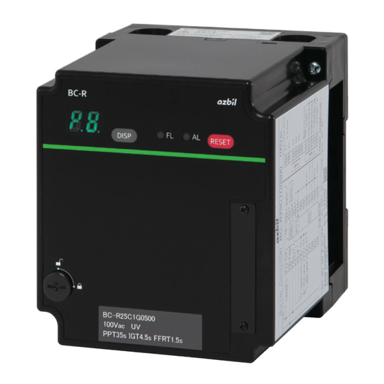
BC-R25 Series
Burner Controller
User's Manual
Thank you for purchasing the BC-R25
Series. This manual contains information
for ensuring the correct use of the BC-R25
Series.
This manual should be read by those who
design and maintain equipment that uses
the BC-R25 Series.
It also provides necessary information
for installation, maintenance, and
troubleshooting. Be sure to keep this
manual nearby for handy reference.
Advertisement
Table of Contents

Related Manuals for Azbil BC-R25 Series


Summary of Contents for Azbil BC-R25 Series
- Page 1 BC-R25 Series. This manual should be read by those who design and maintain equipment that uses the BC-R25 Series. It also provides necessary information for installation, maintenance, and troubleshooting. Be sure to keep this...
- Page 2 If you should find an error or omission, please contact Azbil Corporation. In no event is Azbil Corporation liable to anyone for any indirect, special or consequential damages as a result of using this product. © 2015 Azbil Corporation All Rights Reserved.
- Page 3 Conventions Used in This Manual ■ To prevent injury to the operator and others, and to prevent property damage, the following types of safety precautions are indicated: Warnings are indicated when mishandling this product might result in WARNING death or serious injury. Cautions are indicated when mishandling this product might result in CAUTION minor injury to the user, or physical damage to the product.
- Page 4 This device cannot be used with combustion equipment that operates continuously for 24 hours or longer. Before removing, mounting, or wiring the BC-R25 Series, be sure to turn off the power to the BC-R25 Series and all connected devices. Failure to do so might cause electric shock.
- Page 5 CAUTION Wire this device in compliance with established norms, using the types of wire and wiring methods specified in this manual. Otherwise there is a risk of device failure or malfunction. Carry out maintenance and inspection correctly according to the methods, procedures, replacement cycles, etc., specified in this manual.
-
Page 6: Table Of Contents
Contents Conventions Used in This Manual Safety Precautions Chapter 1. Overview ■ Instructions for proper use ……………………………………………………………… 1 ■ Precautions on facility design …………………………………………………………… 1 ■ Most important points for ensuring safety …………………………………………… 1 ■ Model number …………………………………………………………………………… 2 ■ Related equipment ……………………………………………………………………… 3 Chapter 2. - Page 7 Chapter 6. Maintenance and Inspection ■ General maintenance and inspection ……………………………………………………44 ■ Maintenance and inspection cycle ………………………………………………………44 ■ Alarm codes and details …………………………………………………………………45 ■ Failure inspection flow ……………………………………………………………………46 Chapter 7. Specifications ■ External dimensions ………………………………………………………………………49...
-
Page 9: Chapter 1. Overview
Chapter 1. Overview BC-R25 burner controllers are designed for batch operation of combustion equipment (at least one start and stop in a 24-hour period). The BC-R25 automatically executes ignition, flame monitoring, and fuel shutoff for ON/OFF- controlled gas burners and oil burners. Its features include a 7-segment LED display that is useful for maintenance and a test mode that is convenient for trial runs &... -
Page 10: Model Number
Chapter 1. Overview „ Model number (Note: The dedicated sub-base and sideboard are not provided with the BC-R25 series controller. Order them separately.) z Direct ignition type Example: BC-R25B1J0500 Description Base Commu- Flame Power Function Timing Additional model nications detector... -
Page 11: Related Equipment
Optional parts (sold separately) Model number Product name Notes BC-R05A100 Dedicated sub-base for BC-R Required for all products in the BC-R25 series 81447514-001 Connector for front wiring Contains one Weidmueller model number : BL3.5/11F Compatible wire: 0.2–1.5 mm (28–14 AWG) -
Page 12: Chapter 2. Installation, Wiring
Chapter 2. Installation, Wiring WARNING Never input a reset command from a remote location. Because it is difficult to make a safety check when far from the equipment, there is an increased risk of explosion. This device is equipped with functions that are extremely important for the safe operation of combustion equipment. -
Page 13: Installation Method
Chapter 2. Installation, Wiring CAUTION The reset input (terminal 24) must be used by this device only. It cannot be shared with any other BC-R unit. Output common terminals 4 and 5, and input common terminals 16 and 17 cannot be shared with any other BC-R unit. -
Page 14: Cautions Regarding Installation
Chapter 2. Installation, Wiring „ Cautions regarding installation • Take space 50 mm above and below, 50 mm to the left and right, and 80 mm to the front, as space for removal, wiring, and maintenance. Also, do not install this device close to electric power devices or other sources of heat. Front 50 mm 50 mm... -
Page 15: Mounting In A Panel
Chapter 2. Installation, Wiring „ Mounting in a panel (1) Drill two M4 screw holes into the panel. (Unit: mm) 62.5 (2 locations) (2) Use screws to mount the sub-base on the panel. (Maximum tightening torque: 1.2 N∙m) CAUTION Turn the power off before mounting the device on the sub-base. Otherwise, device failure may occur. -
Page 16: Terminal Numbers, Front Panel Item Names
Chapter 2. Installation, Wiring „ Terminal numbers, front panel item names Front Sub-base (sold separately) Display Reset switch DISP switch Front connector cover (connector is behind cover) Jack * DIN rail clamp Terminal board * Set the POC function as disabled On BC-R25, also used as a Smart Loader Package jack z Terminal No. - Page 17 Chapter 2. Installation, Wiring z Connector for front wiring (81447514-001) terminal layout Mounting screw Wiring Wiring fastener screw Mounting screw z Connector for front wiring (for right side wiring) (81447514-002) terminal layout Mounting screw Wiring Wiring fastener screw Mounting screw...
-
Page 18: Example Of Wiring Connection With External Device
Chapter 2. Installation, Wiring „ Example of wiring connection with external device (Terminals 1 to 24: sub-base. Terminals 25 to 35: front connector.) z Interrupted pilot type L2 (N) Blower motor (electromagnetic Alarm breaker) Flame Flame detector Power supply circuit detector circuit 24 Vdc... - Page 19 Chapter 2. Installation, Wiring z Direct ignition type L2 (N) Blower motor (electromagnetic Alarm breaker) Flame Flame detector Power supply circuit detector circuit 24 Vdc Input common Output common Ignition transformer Combustion Main valve (Lo solenoid valve) Input safety circuit Start Main valve (Hi solenoid valve) control...
- Page 20 Chapter 2. Installation, Wiring z Wiring to a flame detector (UV sensor) • AUD100C+AUD15C Blue Terminal 14 White Terminal 15 • AUD110C+AUD15C Terminal Terminal 14 (F) Terminal 15 • AUD120C+AUD15C Blue Terminal 14 White Terminal 15 If connection of the blue and white lead wires is reversed, or if the connections to terminals F and G are reversed, the AUD15C tube unit may be damaged.
-
Page 21: Chapter 3. Operation
Chapter 3. Operation „ Names of parts BC-R fastening screw 7-segment LED (green) When normal: Sequence code/Flame voltage When an error occurs: Alarm code/Flame voltage DISP switch Reset switch Switch to change as follows: Switch to cancel lock-out Flame voltage/Sequence code or (Press and hold for approximately 1s) Flame voltage/Alarm code ALARM LED (red) - Page 22 Chapter 3. Operation When an error occurs The 7-segment display shows a alarm code and the sequence code for which the alarm was issued alternately. Every time the DISP switch is pressed, the display is changed between a alarm code and the sequence code for which the alarm was issued alternately as well as the flame voltage.
- Page 23 Chapter 3. Operation z Reset switch * Lock-out is canceled when the reset switch is pressed and held for 1 s. * A fter the lock-out is canceled, a stabilization time of approximately 5 seconds should be maintained. During the stabilization time, no start input can be accepted. • During postpurge, reset is not possible.
-
Page 24: Trial Operation Mode
Chapter 3. Operation „ Trial operation mode WARNING Loads(the blower, ignition transformer, valves, etc.) operate in trial operation mode. They should be operated by a person with expert knowledge and an understanding of the functions. There is a risk of a major accident. [1] Press and hold the DISP switch for approximately 5s or more during the stop sequence (when the start input is Off). - Page 25 Chapter 3. Operation [4] Press and hold the DISP switch for 5 s or more to end trial operation mode. Trial operation mode also ends in the following situations. • Power OFF • A larm is issued during trial operation mode (in continuous pilot burn mode). 1.1 Continuous pilot burn mode ( In the combustion sequence, only the pilot burns and main trial is not performed.
-
Page 26: Function Selection Mode (For Poc And Host Communications (Rs-485) Address)
Chapter 3. Operation „ Function selection mode (for POC and host communications (RS-485) address) CAUTION If POC is selected, the lower right dot of the 7-segment display is lit, regardless of the operation mode. If devices installed in the system are set without selecting POC (proof of closure), an E8 error is issued when this device is replaced, unless the new device is set without POC (proof of closure) selection. - Page 27 Chapter 3. Operation • Factory settings • Communications address setting (only on the BC-R25) [7] Use the DISP switch to select 7-segment display [ Settings 1 Press the Reset button. (On the BC-R25, pressing this does not change the display). The 7-segment display shows [ /xx ], where XX is the address value.
-
Page 28: Host Communication Settings Using The Smart Loader Package (Slp-Bcr)
Chapter 3. Operation „ Host communication settings using the Smart Loader Package (SLP-BCR) Function setting mode [ ], [ ] and [ ] (host communication (RS-485) setting) can also be set using the smart loader package. [1] Turn off the power of the product. [2] Remove the wiring of RS-485. -
Page 29: Chapter 4. Explanation Of Operation
Chapter 4. Explanation of Operation CAUTION Even if the start input is turned on, this device does not begin operation until approximately 8 seconds after power supply being turned on. Therefore, give sufficient time after turning on the power, then check the output of the device. As the start input uses a 24 Vdc input circuit, it takes approximately 1 second to confirm it. - Page 30 Chapter 4. Explanation of Operation z Direct ignition type L2 (N) Blower motor (electromagnetic Alarm breaker) Flame Flame detector Power supply circuit detector circuit 24 Vdc Input common Output common Ignition transformer Combustion Main valve (Lo solenoid valve) Input safety Start Main valve (Hi solenoid valve) circuit...
-
Page 31: Example Sequence
Chapter 4. Explanation of Operation „ Example sequence z Normal operation • Interrupted pilot type [7-segment display] Input Power supply Start input Air- ow switch POC (proof of closure) Loc-kout interlock Flame signal Reset Output Blower motor (electromagnetic breaker) Ignition transformer Pilot valve Main valve Alarm output... - Page 32 Chapter 4. Explanation of Operation z Normal operation • Direct ignition type [7-segment display] Input Power supply Start input Air- ow switch POC (proof of closure) Lock-out interlock Flame signal Reset Output Blower motor (electromagnetic breaker) Ignition transformer Main valve (Lo solenoid valve)* Main valve (Hi solenoid valve)* Alarm output Monitor output...
- Page 33 Chapter 4. Explanation of Operation z No ignition • Interrupted pilot type [7-segment display] P4/E6 Input Power supply Start input Air- ow switch POC (proof of closure) Lock-out interlock Flame signal Reset Output Blower motor (electromagnetic breaker) Ignition transformer Pilot valve Main valve Alarm output Monitor output...
- Page 34 Chapter 4. Explanation of Operation z No ignition • Direct ignition type [7-segment display] P4/E6 Input Power supply Start input Air- ow switch POC (proof of closure) Lock-out interlock Flame signal Reset Output Blower motor (electromagnetic breaker) Ignition transformer Main valve (Lo solenoid valve)* Main valve (Hi solenoid valve)* Alarm output Monitor output...
- Page 35 Chapter 4. Explanation of Operation z Flame failure • Interrupted pilot type [7-segment display letter] P8/E7 Input Power supply Start input Air- ow switch POC (proof of closure) Lock-out interlock Flame signal Reset Output Blower motor (electromagnetic breaker) Ignition transformer Pilot valve Main valve Alarm output...
- Page 36 Chapter 4. Explanation of Operation z Flame failure • Direct ignition type [7-segment display letter] P8/E7 Input Power supply Start input Air- ow switch POC (proof of closure) Lock-out interlock Flame signal Reset Output Blower motor (electromagnetic breaker) Ignition transformer Main valve (Lo solenoid valve)* Main valve (Hi solenoid valve)* Alarm output...
- Page 37 Chapter 4. Explanation of Operation z Start input during post-purge • Interrupted pilot type Transition to pre-purge without checking that the air-flow switch is Off or stopping the blower. [7-segment display] Input Power supply Start input Air- ow switch POC (proof of closure) Lock-out interlock Flame signal Reset...
- Page 38 Chapter 4. Explanation of Operation z Start input during post-purge • Direct ignition type Transition to pre-purge without checking that the air-flow switch is Off or stopping the blower. [7-segment display] Input Power supply Start input Air- ow switch POC (proof of closure) Lock-out interlock Flame signal Reset...
- Page 39 Chapter 4. Explanation of Operation z Interlock error • Interrupted pilot type [7-segment display] P8/E0 Input Power supply Start input Air- ow switch POC (proof of closure) Lock-out interlock Flame signal Reset Output Blower motor (electromagnetic breaker) Ignition transformer Pilot valve Main valve Alarm output Monitor output...
- Page 40 Chapter 4. Explanation of Operation z Interlock error • Direct ignition type [7-segment display] P8/E0 Input Power supply Start input Air- ow switch POC (proof of closure) Lock-out interlock Flame signal Reset Output Blower motor (electromagnetic breaker) Ignition transformer Main valve (Lo solenoid valve)* Main valve (Hi solenoid valve)* Alarm output Monitor output...
- Page 41 Chapter 4. Explanation of Operation z False flame occurred during pre-purge (interrupted pilot type / direct ignition type) [7-segment display] P2/E1 Input Power supply Start input Air- ow switch POC (proof of closure) Lock-out interlock Flame signal Reset Output Blower motor (electromagnetic breaker) Ignition transformer Pilot valve Main valve...
- Page 42 Chapter 4. Explanation of Operation z False flame occurred before the start input. Then, the start input was turned ON (interrupted pilot type/direct ignition type) [7-segment display] P1/E1 Input Power supply Start input Air- ow switch POC (proof of closure) Lock-out interlock Flame signal Reset...
- Page 43 Chapter 4. Explanation of Operation z The air-flow switch was not turned ON during pre-purge (interrupted pilot type/direct ignition type) [7-segment display] P2/E3 Input Power supply Start input Air- ow switch POC (proof of closure) Lock-out interlock Flame signal Reset Output Blower motor (electromagnetic breaker) Ignition transformer...
- Page 44 Chapter 4. Explanation of Operation z Lock-out interlock Off (open) at start input (interrupted pilot type/direct ignition type) [7-segment display] P1/E0 Input Power supply Start input Air- ow switch POC (proof of closure) Lock-out interlock Flame signal Reset Output Blower motor (electromagnetic breaker) Ignition transformer Pilot valve Main valve...
-
Page 45: Alarm And Occurrence Sequence
Chapter 4. Explanation of Operation „ Alarm and occurrence sequence Name Symbol Interlock False flame Air-flow Air-flow Ignition Flame Error switch switch failure failure (proof of error (1) error (2) closure) error E3 / EA Stop −− Start check Pre-purge Ignition trial Pilot stabilization / Hi-valve ignition standby... -
Page 46: Chapter 5. Trial Operation And Adjustment
Chapter 5. Trial Operation and Adjustment WARNING Make sure that the ignition times for the pilot and main burners do not exceed the ignition times specified by the burner or device manufacturer. Excessive ignition times may cause fuel to accumulate in the combustion chamber and form an explosive fuel-air mixture, which can result in a serious explosion hazard. -
Page 47: Ignition Spark Response (Uv Sensor)
Chapter 5. Trial Operation and Adjustment „ Ignition spark response (UV sensor) WARNING Ensure that the UV sensor does not detect ultraviolet rays other than those from the burner. If the UV sensor responds to other ultraviolet radiation, fuel will continue to be supplied even if the burner flame is off, potentially causing an explosion. -
Page 48: Measurement Of Flame Voltage
Chapter 5. Trial Operation and Adjustment „ Measurement of flame voltage This device shows the flame voltage on the 7-segment display. It can be checked by changing the display using the DISP switch on the front of the device. Checking the flame voltage is the best way to determine whether or not the location of the flame detector is appropriate. - Page 49 Analog ame meter Flame voltage display FSP136A100 * Connector for front wiring (81447514-001/002) is required to connect FSP136A100 to BC-R25 series. Handling Precautions • For flame voltage output signal wires, use wire with indoor PVC insulation ("IV wire," JIS C3307) 0.75 mm .
-
Page 50: Pilot Turn-Down Test
Chapter 5. Trial Operation and Adjustment „ Pilot turn-down test WARNING Make sure that the pilot turn-down test is done properly. If the flame detector is able to detect a pilot flame that is too small to ignite the main burner, and if there is a flame failure of the main burner, this device will not be able to recognize the flame failure. -
Page 51: Safety Shutoff Check
Chapter 5. Trial Operation and Adjustment (5) Turn off the power switch, return the main valve to the normal state and then turn on the power switch again. After the pre-purge, pilot burner combustion begins and then main burner combustion begins. If the main burner does not ignite, turn off the power switch immediately. The pilot flame is too small, so it must be increased. -
Page 52: Chapter 6. Maintenance And Inspection
Chapter 6. Maintenance and Inspection WARNING Ensure you turn off the power of this device and all auxiliary devices when mounting, removing or connecting the wires of this device. There is a risk of electrical shock. Terminal 14 (F) retains an electrical charge even after the power is turned off. Do not touch terminal 14 (F) even after turning the power off. -
Page 53: Alarm Codes And Details
Chapter 6. Maintenance and Inspection „ Alarm codes and details When lock-out occurs, an alarm code is displayed automatically. When an alarm occurs, the sequence number and alarm code issued when the lock-out occurred are displayed alternately. Refer to chapter 4, “Relationship between Error Occurrence and Sequence. -
Page 54: Failure Inspection Flow
Chapter 6. Maintenance and Inspection „ Failure inspection flow WARNING Before removing, mounting, or wiring the module, be sure to turn OFF the power to the module and all connected devices. Failure to do so may result in an electric shock. If there is any problem with the device, follow the inspection procedure below. -
Page 55: Chapter 7. Specifications
Chapter 7. Specifications Item Description Application Batch-operated combustion systems burning gas, oil, or gas/oil mixture Compatible flame detector AUD100/110/120 series UV sensor, flame rod Sequence Sequence timing Pre-purge Ignition trial Pilot stabilization Main trial Post-purge (Hi-valve ignition (Hi-valve ignition) standby) * 35 s, 45 s, 60 s, 3 min 4.5±0.5 s 8.5±1 s... - Page 56 Chapter 7. Specifications General Protection rating IP40 (with sideboards (81447515-001) attached to the sub-base (BC-R05)) specifications IP10 (sub-base (BC-R05) only) Overvoltage category Pollution degree Case color Black Case material Denatured PPE resin (UL94-V0 PTI Material group IIIa) Structure Sub-base and main device Mounted Vertical or horizontal orientation...
-
Page 57: External Dimensions
Chapter 7. Specifications „ External dimensions (Unit: mm) z Body Sub-base (sold separately) BC-R fastening screw Sub-base Connector for (sold separately) front wiring BC-R fastening screw DIN rail clamp Model number 81447514-001 10.6 81447514-002 14.6... - Page 58 Chapter 7. Specifications (Unit: mm) z Sub-base BC-R05A100 (sold separately) Knockout hole Knockout hole M3.5 (terminal screw) φ12 knockout hole φ12 knockout hole Sub-base mounting hole Sub-base mounting hole DIN rail clamp 62.5 z Sideboard 81447515-001 (sold separately) 30.7 Sub-base Sub-base φ19 knockout hole Sideboard...
- Page 59 Revision History of CP-SP-1388E Printed Edn. Revised pages Description Jan. 2015 Jun. 2015 ii, iii Warnings and cautions were partly revised in the Safety Precautions section. 4, 5 Warnings and cautions were partly revised in Chapter 2. 47, 48 "*" was changed to "*1." "*2" was added to the end of "Monitor outputs."...
- Page 60 Warranty period and warranty scope 1.1 Warranty period Azbil Corporation's products shall be warranted for one (1) year from the date of your purchase of the said products or the delivery of the said products to a place designated by you.
- Page 61 Azbil Corporation's products every 5 to 10 years unless otherwise specified in specifications or instruction manuals.
- Page 62 Specifications are subject to change without notice. (09) 1-12-2 Kawana, Fujisawa Kanagawa 251-8522 Japan URL: http://www.azbil.com 1st edition: Jan. 2015 (K) 2nd edition: Jun. 2015 (V)
Need help?
Do you have a question about the BC-R25 Series and is the answer not in the manual?
Questions and answers