Table of Contents
Advertisement
Quick Links
USER MANUAL
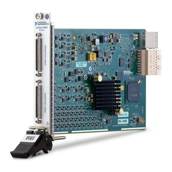
NI PXIe-7846R
R Series Reconfigurable I/O Module (AI, AO, DIO) for PXI Express,
8 AI, 8 AO, 48 DIO, 500 kS/s AI, Kintex-7 160T FPGA
This document provides compliance, pinout, connectivity, mounting, and power information
for the NI PXIe-7846R.
Hardware Overview
The following high-level block diagram represents the NI PXIe-7846R.
Overvoltage
Protection
Overvoltage
Protection
Overvoltage
Protection
Overvoltage
Protection
Figure 1. NI PXIe-7846R Block Diagram
AI (x8)
ADC
INA
+5 V
Reference
AO (x8)
DAC
DIO (x16)
DIO (x32)
Device
Temperature
100 MHz
OSC
AI
AO
Data/
Kintex-7
Address/
FPGA
Control
DIO
Flash
Memory
NI ASIC
NI PXIe-7846R
Advertisement
Table of Contents

Related Manuals for National Instruments PXIe-7846R


Summary of Contents for National Instruments PXIe-7846R
- Page 1 8 AI, 8 AO, 48 DIO, 500 kS/s AI, Kintex-7 160T FPGA This document provides compliance, pinout, connectivity, mounting, and power information for the NI PXIe-7846R. Hardware Overview The following high-level block diagram represents the NI PXIe-7846R. Figure 1. NI PXIe-7846R Block Diagram 100 MHz Flash...
- Page 2 Positive analog input signal connection Negative analog input signal connection AISENSE Reference connection for NRSE measurements AIGND Ground reference for the analog input signal Analog output signal connection AOGND Ground reference for the analog output signal 2 | ni.com | NI PXIe-7846R User Manual...
-
Page 3: Connectivity Options
The provided clock source must be stable and glitch-free. Ground connection Supply (+5 Vout) 5 V power output connection for external devices No connection The NI PXIe-7846R is protected from overvoltage and overcurrent conditions. Note Refer to the device specifications, available at ni.com/manuals for more information. -
Page 4: Analog Input
Analog Input The NI PXIe-7846R provides connections for eight AI channels. Each channel has an AI+ pin, AI- pin, and AIGND pin to which you can connect both single-ended or differential voltage signals. Use the AISENSE pin to connect non-referenced single-ended signals. -
Page 5: Analog Output
You can connect grounded or floating differential signal sources to the NI PXIe-7846R. Connect the positive voltage signal to the AI+ and the negative voltage signal to AI-. To connect grounded differential signals to the NI PXIe-7846R, you must also connect the signal reference to AI GND. - Page 6 Accessory Digital I/O The NI PXIe-7846R provides connections for 48 digital input/output (DIO) channels. Connector 0 contains 16 low-speed channels that can run up to 10 MHz signal frequencies and Connector 1 contains 32 high-speed DIO channels that can run up to 80 MHz signal frequencies.
-
Page 7: Field Wiring Considerations
When the system powers on, the DIO channels are set as input low with pull-down resistors. To set another power-on state, you can configure the NI PXIe-7846R to load a VI when the system powers on. The VI can then set the DIO lines to any power-on state. -
Page 8: Worldwide Support And Services
National Instruments is not liable for damage resulting from such a connection. The power rating is 4.75 to 5.1 VDC at 0.5 A. Worldwide Support and Services The NI website is your complete resource for technical support. At ni.com/support, you have access to everything from troubleshooting and application development self-help resources to email and phone assistance from NI Application Engineers.
Need help?
Do you have a question about the PXIe-7846R and is the answer not in the manual?
Questions and answers