Table of Contents
Advertisement
Quick Links
UM2408
User manual
STM32H7 Nucleo-144 boards (MB1363)
Introduction
The STM32H7 Nucleo-144 boards based on the MB1363 reference board (NUCLEO-
H745ZI-Q, NUCLEO-H755ZI-Q) provide an affordable and flexible way for users to try out
new concepts and build prototypes, by choosing from the various combinations of
performance and power consumption features provided by the STM32H7 microcontroller.
The ST Zio connector, which extends the Arduino™ Uno V3 connectivity, and the ST
morpho headers provide an easy means of expanding the functionality of the Nucleo open
development platform with a wide choice of specialized shields. The STM32H7 Nucleo-144
boards do not require any separate probe as they integrate the ST-LINK/V3
debugger/programmer. The STM32H7 Nucleo-144 boards come with the comprehensive
free software libraries and examples available with the STM32Cube MCU Package.
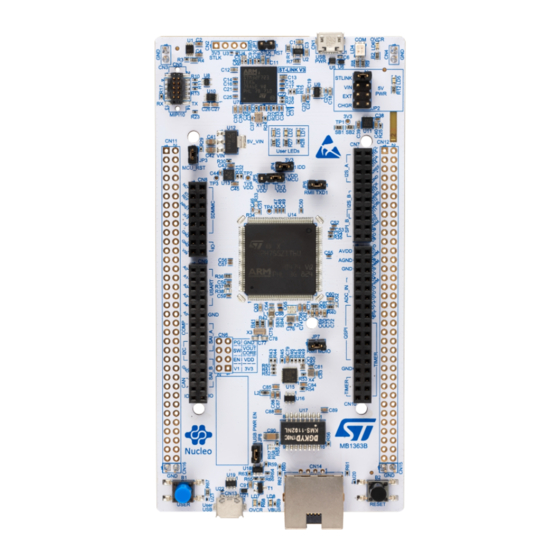
Figure 1. Nucleo-144 board (top view)
Figure 2. Nucleo-144 board (bottom view)
Pictures are not contractual.
March 2019
UM2408 Rev 1
1/45
www.st.com
1
Advertisement
Table of Contents

Related Manuals for ST NUCLEO-H745ZI-Q


Summary of Contents for ST NUCLEO-H745ZI-Q
-
Page 1: Figure 1. Nucleo-144 Board (Top View)
STM32H7 microcontroller. The ST Zio connector, which extends the Arduino™ Uno V3 connectivity, and the ST morpho headers provide an easy means of expanding the functionality of the Nucleo open development platform with a wide choice of specialized shields. -
Page 2: Table Of Contents
Program and Debug the on-board STM32H7 target ....16 6.3.1 Using the ST-LINK/V3 to program and debug the on-board STM32H7 . 16 6.3.2 Using an external debug tool to program and debug the on-board STM32H7 . - Page 3 ST Zio connectors ........
- Page 4 Solder bridges............31 Table 17. NUCLEO-H745ZI-Q and NUCLEO-H755ZI-Q pin assignments ..... 35 Table 18.
- Page 5 Power supply input from 5V_EXT (5 V, 500 mA max) ......21 Figure 11. Power supply input from ST-LINK USB connector with USB charger (5 V) ... . 21 Figure 12.
-
Page 6: Features
™ – ST Zio including Arduino Uno V3 – ST morpho • Flexible power-supply options: ST-LINK USB V or external sources • On-board ST-LINK/V3 debugger/programmer with SWD connector: – USB re-enumeration capability: virtual COM port, mass storage, debug port –... -
Page 7: Ordering Information
Any consequences deriving from such usage will not be at ST charge. In no event, ST will be liable for any customer usage of these engineering sample tools as reference design or in production. - Page 8 Ordering information UM2408 Table 2. Codification explanation NUCLEO-TXXXZY Description Example: NUCLEO-H745ZI STM32H7 Flash memory size 2 Mbytes -I for 2 Mbytes STM32n has SMPS function Int-SMPS The order code is mentioned on a sticker placed on top side of the board. 8/45 UM2408 Rev 1...
-
Page 9: Development Environment
STM32H7 Flash memory for easy demonstration of the device peripherals in standalone mode. The latest versions of the demonstration source code and associated documentation can be downloaded from the www.st.com/stm32nucleo web page. a. On Windows only. b. macOS is a trademark of Apple Inc., registered in the U.S. and other countries. -
Page 10: Conventions
Conventions UM2408 Conventions Table 3 provides the conventions used for the ON and OFF settings in the present document. Table 3. ON/OFF conventions Convention Definition Jumper JPx ON Jumper fitted Jumper JPx OFF Jumper not fitted Solder bridge SBx ON SBx connections closed by solder or 0 ohm resistor Solder bridge SBx OFF SBx connections left open... -
Page 11: Quick Start
To power the board connect the STM32H7 Nucleo-144 board to a PC with a USB cable ‘Type-A to Micro-B’ through the USB connector CN1 on the ST-LINK. As a result, the green LED LD6 (PWR) and LD4 (COM) light up and the red LED LD3 blinks. -
Page 12: Hardware Layout And Configuration
144-pin LQFP package. Figure 3 shows the connections between the STM32H7 and its peripherals (ST-LINK/V3, push-buttons, LEDs, USB, Ethernet, ST Zio connectors and ST morpho headers) for H745ZI-Q and H755ZI-Q. Figure 4 shows the location of these features on the STM32H7 Nucleo-144 board. -
Page 13: Nucleo-144 Board Layout
UM2408 Hardware layout and configuration Nucleo-144 board layout Figure 4. Nucleo-144 board top layout UM2408 Rev 1 13/45... -
Page 14: Mechanical Drawing
Hardware layout and configuration UM2408 Mechanical drawing Figure 5. Nucleo-144 board mechanical drawing in millimeter 14/45 UM2408 Rev 1... -
Page 15: Figure 6. Nucleo-144 Board Mechanical Drawing In Mil
UM2408 Hardware layout and configuration Figure 6. Nucleo-144 board mechanical drawing in mil UM2408 Rev 1 15/45... -
Page 16: Program And Debug The On-Board Stm32H7 Target
Green LED ON: 5 V enabled (LD5) How to use It is very easy to use the ST-LINK/V3 to program and debug the on-board STM32H7. Verify that the jumper JP2 of Power Supply Sources is correctly set. (see chapter 2.3) Connect the board to a PC with a USB cable 'type A to micro-B' through the USB connector CN1. -
Page 17: Using An External Debug Tool To Program And Debug The On-Board
ST-LINK/V3 firmware upgrade The ST-LINK/V3 embeds a firmware upgrade mechanism for in-situ upgrade through the USB port. As the firmware may evolve during the lifetime of the ST-LINK/V3 product (for example new functionalities, bug fixes, support for new microcontroller families), it is recommended to keep the ST-LINK/V3 firmware up to date before starting to use the STM32H7 Nucleo-144 board. -
Page 18: Power Supply And Power Selection
EN-60950-1: 2006+A11/2009 and must be Safety Extra Low Voltage (SELV) with limited power capability. In case the power supply is 3.3 V or a 5 V USB charger on CN1, the ST-LINK is not powered and cannot be used. -
Page 19: External Power Supply Input From V
UM2408 Hardware layout and configuration Figure 8. Power supply input from ST-LINK USB connector with PC (5 V, 500 mA max) If the USB enumeration succeeds, the 5V_ST_LINK power is enabled, by asserting the PWR_ENn signal from STM32F723IEK6 "STLINK V3" (U7). This pin is connected to a power switch STMPS2151STR (U2), which powers the board. -
Page 20: External Power Supply Input 5V_Ext (5 V, 500 Ma Max)
Hardware layout and configuration UM2408 Table 5. External power sources: V (7-11 V) Input power Connector pins Voltage range Max current Limitation name From 7 V to 11 V only and input current capability is linked to input voltage: CN8 pin 15 –... -
Page 21: External Power Supply Input From Usb Charger (5V)
Voltage range Max current CHGR Figure 11. Power supply input from ST-LINK USB connector with USB charger (5 V) 6.4.5 External power supply input from 3V3_EXT (3.3 V) When the 3.3V is provided by a shield board, it is interesting to use the 3.3 V (CN8 pin 7 or... -
Page 22: Debugging While Using V
EXT as an external power supply When powered by V or EXT, it is still possible to use the ST-LINK for programming or debugging only, but it is mandatory to power the board first using V or EXT, then to connect the USB cable to the PC. -
Page 23: External Power Supply Output
When powered by USB, VIN or EXT, the 5V (CN8 pin 9 or CN11 pin 18) can be used as output power supply for an ST Zio shield or an extension board. In this case, the maximum current of the power source specified in... -
Page 24: Figure 13. Supply Configuration 1: Internal Ldo Only
Hardware layout and configuration UM2408 Table 10. SMPS / LDO configuration (continued) Supply config 2: Supply config 3: Supply config 1: Supply config 5: Internal SMPS only Internal SMPS & Internal LDO only external SMPS (default) LDO cascaded SB97 SB95 Figure 13. -
Page 25: Jp5: 1.8 V / 3.3 V Selection
UM2408 Hardware layout and configuration Figure 15. Supply configuration 3: Internal SMPS & LDO cascaded Figure 16. Supply configuration 4: external SMPS 6.4.9 JP5: 1.8 V / 3.3 V selection JP5, labeled "VDD_MCU" is used to select the VDD supply for the MCU: •... -
Page 26: Leds
User LD1: a green user LED is connected to the STM32H7 I/O PB0 (SB39 ON and SB47 OFF) or PA5 (SB65 ON and SB54 OFF) corresponding to the ST Zio D13. User LD2: a yellow user LED is connected to PE1. -
Page 27: Push-Buttons
There are four ways to configure the pins corresponding to the external high-speed clock (HSE): • MCO from ST-LINK (default): MCO output of ST-LINK is used as input clock. This frequency cannot be changed, it is fixed at 8 MHz and connected to the PH0-OSC_IN of STM32H7 microcontroller. The configuration must be: –... -
Page 28: Osc 32 Khz
The USART3 interface available on PD8 and PD9 of the STM32H7 can be connected either to ST-LINK or to ST morpho connector. The choice is changed by setting the related solder bridges. By default, the USART3 communication between the target STM32H7 and the STLINK is enabled, to support the Virtual COM port for the Mbed (SB16 and SB17 ON). -
Page 29: Usb Otg Fs Or Device
Note: 1.It is recommended to power Nucleo-144 board by an external power supply when using USB OTG or host function. Table 13. USB pin configuration Configuration when using Configuration when using ST Function Remark name USB connector morpho connector... -
Page 30: Ethernet
(Power Down) to '1'. SB80 can also be removed to get the same effect. Table 14. Ethernet pin configuration Conflict Configuration with ST when using ST Pin name Function Configuration when using Ethernet Zio or ST morpho connector connector signal RMII Ref H745ZI-Q / H755ZI-Q: SB80 ON SB80 OFF Clock RMII MDIO A8... -
Page 31: Solder Bridges
Output of voltage regulator ST1L05CPU33R is not connected. PD8 and PD9 on STM32H7 are connected to ST morpho connectors CN11 and CN12. If these pins are used on ST morpho connectors, SB103, SB104 SB16, SB17, SB15 & SB94 must be OFF. - Page 32 (X2, C76, C74, SB3 and SB4 provide a clock as shown in Section (PH1) (Main clock) OFF, OFF Appendix A: Electrical schematics. In this case SB72 must be removed). PH0 and PH1 are connected to ST morpho connector CN11. SB3, SB4, ON, ON and SB72 must be removed). 32/45 UM2408 Rev 1...
- Page 33 PA0 is connected to ST Zio connector (Pin 29 of CN10) SB89 (PA0) PA0 is not connected to ST Zio connector (Pin 29 of CN10) ON, ON, PC2, PF11 (ADC) are connected to A4 and A5 (pin 9 and 11) on ST Zio SB69,SB40 (ADC OFF, OFF connector CN9.
-
Page 34: Extension Connectors
6.15 Extension connectors For each STM32H7 Nucleo-144 board, the following figures show the signals connected by default to the ST Zio connectors (CN7, CN8, CN9, CN10), including the support for Arduino Uno V3. Figure 17. NUCLEO-H745ZI-Q and NUCLEO-H755ZI-Q extension connectors... -
Page 35: St Zio Connectors
REF+ on CN7 pin 6. Refer to Table 16: Solder bridges for details on R40. Table 17 shows the pin assignment for each STM32H7 microcontroller on the ST Zio connectors. Table 17. NUCLEO-H745ZI-Q and NUCLEO-H755ZI-Q pin assignments Connector Signal name... - Page 36 Hardware layout and configuration UM2408 Table 17. NUCLEO-H745ZI-Q and NUCLEO-H755ZI-Q pin assignments (continued) Connector Signal name STM32H7 pin Function Remark name Left connector ADC_12_INP15 Arduino support ADC_123_INP10 Arduino support PC3_C ADC_3_INP1 Arduino support ADC_12_INP5 Arduino support PC2_C or ADC3_INP0 (PC2_C)
- Page 37 UM2408 Hardware layout and configuration Table 17. NUCLEO-H745ZI-Q and NUCLEO-H755ZI-Q pin assignments (continued) Connector Signal name STM32H7 pin Function Remark name Left connector I2S_A_MCK I2S_2 I2S_A_SD PB15 I2S_2 (10) I2S_A_CK PB13 I2S_2 NC by default I2S_A_WS PB12 I2S_2 I2S_B_WS PA15...
- Page 38 Hardware layout and configuration UM2408 Table 17. NUCLEO-H745ZI-Q and NUCLEO-H755ZI-Q pin assignments (continued) Connector Signal name STM32H7 pin Function Remark name Left connector VDDA VDDA Analog VDD AGND AGND Analog ground ground ADC_A_IN ADC3_INP8 ADC_B_IN PF10 ADC3_INP6 (13) ADC_C_IN ADC12_INP14...
- Page 39 UM2408 Hardware layout and configuration 1. PC9 = SDMMC_D1 / SAI2_EXTCLK 2. PG10 = D49 / SMPS_SW 3. PG8 = D50 / SMPS_V1 4. PB2 = D27 / D72 5. PB5 = D11 / D22 / D70 6. PB14 = D65 / LED_RED 7.
-
Page 40: Appendix A Assembly Drawings
Assembly drawings UM2408 Appendix A Assembly drawings Figure 18. Top assembly drawing 40/45 UM2408 Rev 1... -
Page 41: Figure 19. Bottom Assembly Drawing
UM2408 Assembly drawings Figure 19. Bottom assembly drawing UM2408 Rev 1 41/45... -
Page 42: Appendix B Federal Communications Commission (Fcc)
Federal Communications Commission (FCC) and Industry Canada (IC) Compliance UM2408 Appendix B Federal Communications Commission (FCC) and Industry Canada (IC) Compliance FCC Compliance Statement B.1.1 Part 15.19 This device complies with Part 15 of the FCC Rules. Operation is subject to the following two conditions: (1) this device may not cause harmful interference, and (2) this device must accept any interference received, including interference that may cause undesired operation. -
Page 43: Déclaration De Conformité
UM2408 Federal Communications Commission (FCC) and Industry Canada (IC) Compliance Industry Canada ICES-003 Compliance Label: CAN ICES-3 (A)/NMB-3(A) B.2.2 Déclaration de conformité Avis: Le présent appareil est conforme aux CNR d'Industrie Canada applicables aux appareils radio exempts de licence. L'exploitation est autorisée aux deux conditions suivantes: (1) l'appareil ne doit pas produire de brouillage, et (2) l'utilisateur de l'appareil doit accepter tout brouillage radioélectrique subi, même si le brouillage est susceptible d'en compromettre le fonctionnement... -
Page 44: Revision History
Revision history UM2408 Revision history Table 18. Document revision history Date Revision Changes 13-Mar-2019 Initial version 44/45 UM2408 Rev 1... - Page 45 ST products and/or to this document at any time without notice. Purchasers should obtain the latest relevant information on ST products before placing orders. ST products are sold pursuant to ST’s terms and conditions of sale in place at the time of order acknowledgement.
Need help?
Do you have a question about the NUCLEO-H745ZI-Q and is the answer not in the manual?
Questions and answers