Table of Contents
Advertisement
UM2408
User manual
STM32H7 Nucleo-144 boards (MB1363)
Introduction
The STM32H7 Nucleo-144 boards based on the MB1363 reference board (NUCLEO-
H745ZI-Q, NUCLEO-H755ZI-Q, NUCLEO-H7A3ZI-Q) provide an affordable and flexible
way for users to try out new concepts and build prototypes, by choosing from the various
combinations of performance and power consumption features provided by the STM32H7
®
microcontroller. The ST Zio connector, which extends the ARDUINO
Uno V3 connectivity,
and the ST morpho headers provide an easy means of expanding the functionality of the
Nucleo open development platform with a wide choice of specialized shields. The STM32H7
Nucleo-144 boards do not require any separate probe as they integrate the STLINK-V3E
debugger/programmer. The STM32H7 Nucleo-144 boards come with the comprehensive
free software libraries and examples available with the STM32Cube MCU Package.
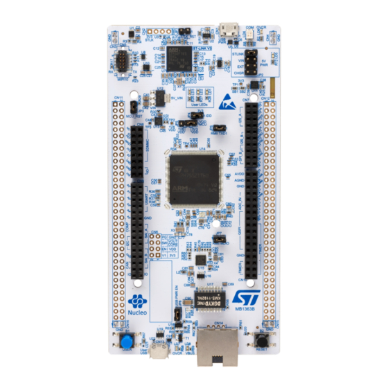
Figure 1. Nucleo-144 board (Top view)
Figure 2. Nucleo-144 board (Bottom view)
Pictures are not contractual.
December 2019
UM2408 Rev 2
1/51
www.st.com
1
Arrow.com.
Downloaded from
Advertisement
Table of Contents

Related Manuals for ST NUCLEO-H745ZI-Q


Summary of Contents for ST NUCLEO-H745ZI-Q
-
Page 1: Figure 1. Nucleo-144 Board (Top View)
The ST Zio connector, which extends the ARDUINO Uno V3 connectivity, and the ST morpho headers provide an easy means of expanding the functionality of the Nucleo open development platform with a wide choice of specialized shields. The STM32H7 Nucleo-144 boards do not require any separate probe as they integrate the STLINK-V3E debugger/programmer. -
Page 2: Table Of Contents
Contents UM2408 Contents Features ........... 6 Ordering information . - Page 3 ST Zio connectors ........
- Page 4 Solder bridges............31 Table 17. NUCLEO-H745ZI-Q and NUCLEO-H755ZI-Q pin assignments ..... 37 Table 18.
- Page 5 USB composite device ........... . 16 Figure 8. Power supply input from ST-LINK USB connector with PC (5 V, 500 mA max) ..18 Figure 9.
-
Page 6: Features
2 push-buttons: user and reset • LSE crystal: – 32.768 kHz crystal oscillator • Board connectors: – USB with Micro-AB – Ethernet RJ45 (Only for NUCLEO-H745ZI-Q and NUCLEO-H755ZI-Q) • Board expansion connectors: ® – ST Zio including ARDUINO Uno V3 – ST morpho •... -
Page 7: Ordering Information
Any consequences deriving from such usage will not be at ST charge. In no event, ST will be liable for any customer usage of these engineering sample tools as reference designs or in production. -
Page 8: Development Environment
The demonstration software, included in the STM32Cube package, is preloaded in the STM32H7 Flash memory for easy demonstration of the device peripherals in standalone mode. The latest versions of the demonstration source code and associated documentation can be downloaded from the www.st.com/stm32nucleo web page. a. On Windows only. ®... -
Page 9: Conventions
UM2408 Conventions Conventions Table 3 provides the conventions used for the ON and OFF settings in the present document. Table 3. ON/OFF conventions Convention Definition Jumper JPx ON Jumper fitted Jumper JPx OFF Jumper not fitted Solder bridge SBx ON SBx connections closed by solder or 0-ohm resistor Solder bridge SBx OFF SBx connections left open... -
Page 10: Quick Start
Power the board by connecting the STM32H7 Nucleo-144 board to a PC with a USB cable ‘Type-A to Micro-B’ through the USB connector CN1 on the ST-LINK. As a result, the green LED LD5 (PWR) and LD4 (COM) light up and the red LED LD3 blinks. -
Page 11: Hardware Layout And Configuration
144-pin LQFP package. Figure 3 shows the connections between the STM32H7 and its peripherals: STLINK-V3E, push-buttons, LEDs, USB, Ethernet (Only on NUCLEO-H745ZI-Q and NUCLEO-H755ZI-Q), ST Zio connectors and ST morpho headers. Figure 4 shows the location of these features on the STM32H7 Nucleo-144 board. -
Page 12: Nucleo-144 Board Layout
Hardware layout and configuration UM2408 Nucleo-144 board layout Figure 4. Nucleo-144 board top layout 12/51 UM2408 Rev 2 Arrow.com. Arrow.com. Arrow.com. Arrow.com. Arrow.com. Arrow.com. Arrow.com. Arrow.com. Arrow.com. Arrow.com. Arrow.com. Arrow.com. Downloaded from Downloaded from Downloaded from Downloaded from Downloaded from Downloaded from Downloaded from Downloaded from... -
Page 13: Mechanical Drawing
UM2408 Hardware layout and configuration Mechanical drawing Figure 5. Nucleo-144 board mechanical drawing in millimeter UM2408 Rev 2 13/51 Arrow.com. Arrow.com. Arrow.com. Arrow.com. Arrow.com. Arrow.com. Arrow.com. Arrow.com. Arrow.com. Arrow.com. Arrow.com. Arrow.com. Arrow.com. Downloaded from Downloaded from Downloaded from Downloaded from Downloaded from Downloaded from Downloaded from... -
Page 14: Figure 6. Nucleo-144 Board Mechanical Drawing In Mil
Hardware layout and configuration UM2408 Figure 6. Nucleo-144 board mechanical drawing in mil 14/51 UM2408 Rev 2 Arrow.com. Arrow.com. Arrow.com. Arrow.com. Arrow.com. Arrow.com. Arrow.com. Arrow.com. Arrow.com. Arrow.com. Arrow.com. Arrow.com. Arrow.com. Arrow.com. Downloaded from Downloaded from Downloaded from Downloaded from Downloaded from Downloaded from Downloaded from Downloaded from... -
Page 15: Program And Debug The Onboard Stm32H7 Target
CN1. Note: For more details regarding the STLINK-V3E functionalities, refer to the STLINK-V3E user manual on the www.st.com website Drivers Before connecting the product via USB to a PC running on Windows 7 or 8, a driver for the STLINK-V3E must be installed (Not required for Windows 10). -
Page 16: Using An External Debug Tool To Program And Debug The Onboard Stm32H7
(For example new functionalities, bug fixes, support for new microcontroller families), it is recommended to keep the STLINK-V3E firmware up to date before starting to use the STM32H7 Nucleo-144 board. The latest version of this firmware is available from the www.st.com website. 6.3.2... -
Page 17: Power Supply And Power Selection
EN-60950-1: 2006+A11/2009 and must be Safety Extra Low Voltage (SELV) with limited power capability. In case the power supply is 3.3 V or a 5 V USB charger on CN1, the ST-LINK is not powered and cannot be used. -
Page 18: External Power Supply Input From Vin (7-11 V, 800 Ma Max)
UM2408 This is the default setting. Figure 8. Power supply input from ST-LINK USB connector with PC (5 V, 500 mA max) If the USB enumeration succeeds, the 5V_ST_LINK power is enabled, by asserting the PWR_ENn signal from STM32F723IEK6 ‘STLINK V3’ (U7). This pin is connected to a power switch STMPS2151STR (U2), which powers the board. -
Page 19: External Power Supply Input 5V_Ext (5 V, 500 Ma Max)
UM2408 Hardware layout and configuration Table 5. External power sources: V (7-11 V) Input power Connector pins Voltage range Max current Limitation name From 7 V to 11 V only and input current capability is linked to input voltage: CN8 pin 15 –... -
Page 20: External Power Supply Input From Usb Charger (5V)
Voltage range Max current CHGR Figure 11. Power supply input from ST-LINK USB connector with a USB charger (5 V) 6.4.5 External power supply input from 3V3_EXT (3.3 V) When the 3.3V is provided by a shield board, it is interesting to use the 3.3 V (CN8 pin 7 or... -
Page 21: Debugging While Using V
EXT as an external power supply When powered by V or EXT, it is still possible to use the ST-LINK for programming or debugging only, but it is mandatory to power the board first using V or EXT, then to connect the USB cable to the PC. -
Page 22: External Power Supply Output
When powered by USB, VIN or EXT, the 5V (CN8 pin 9 or CN11 pin 18) can be used as an output power supply for an ST Zio shield or an extension board. In this case, the maximum current of the power source specified in... -
Page 23: Figure 13. Supply Configuration 1: Internal Ldo Only
UM2408 Hardware layout and configuration Table 10. SMPS / LDO configuration (continued) Supply config 2: Supply config 3: Supply config 1: Supply config 5: Internal SMPS only Internal SMPS and Internal LDO only external SMPS (Default) LDO cascaded SB97 SB95 Figure 13. -
Page 24: Figure 15. Supply Configuration 3: Internal Smps And Ldo Cascaded
Hardware layout and configuration UM2408 Figure 15. Supply configuration 3: Internal SMPS and LDO cascaded Figure 16. Supply configuration 4: external SMPS Warning: Board SMPS/LDO FW PWR configuration must match with the HW configuration. If not, the user faces a deadlock: after the reset, STLINK can't connect the target anymore. -
Page 25: Jp5: 1.8 V / 3.3 V Selection
UM2408 Hardware layout and configuration If a deadlock is faced due to a mismatch between the HW board setting and the FW setting (LDO/SMPS), the user can recover the board by doing the following: - Power off the board - Connect CN11 ‘BT0’ pin (BOOT0) to VDD using a wire - This changes the BOOT0 pin to 1 instead of 0 and thus the device boot address is changed to boot address 1 making the bootloader starting in System memory, instead of starting the... -
Page 26: Leds
User LD1: a green user LED is connected to the STM32H7 I/O PB0 (SB65 OFF and SB54 ON) or PA5 (SB65 ON and SB54 OFF) corresponding to the ST Zio D13. User LD2: a yellow user LED is connected to PE1. -
Page 27: Jp4 (Idd)
(HSE): • MCO from ST-LINK (Default): MCO output of ST-LINK is used as an input clock. This frequency cannot be changed, it is fixed at 8 MHz and connected to the PH0-OSC_IN of the STM32H7 microcontroller. The configuration must be: –... -
Page 28: Osc 32 Khz
The USART3 interface available on PD8 and PD9 of the STM32H7 can be connected either to ST-LINK or to the ST morpho connector. The choice is changed by setting the related solder bridges. By default, the USART3 communication between the target STM32H7 and the STLINK is enabled, to support the Virtual COM port for the Mbed (SB16 and SB17 ON). -
Page 29: Usb Otg Fs Or Device
Note: 1.It is recommended to power the Nucleo-144 board by an external power supply when using USB OTG or host function. Table 13. USB pin configuration Configuration when using USB Configuration when using ST Function Remark name connector morpho connector... -
Page 30: Ethernet (Only With Nucleo-H745Zi-Q And Nucleo-H755Zi-Q)
Hardware layout and configuration UM2408 6.12 Ethernet (Only with NUCLEO-H745ZI-Q and NUCLEO-H755ZI- The STM32H7 Nucleo-144 board supports 10M/100M Ethernet communication by a PHY LAN8742A-CZ-TR (U15) and RJ45 connector (CN14). Ethernet PHY is connected to the STM32H7 microcontroller via the RMII interface. 50 MHz clock for the STM32H7 microcontroller is generated by the PHY RMII_REF_CLK. -
Page 31: Motor Control
Output of voltage regulator ST1L05CPU33R is not connected. PD8 and PD9 on STM32H7 are connected to ST morpho connectors CN11 and CN12. If these pins are used on ST morpho SB103, SB104 connectors, SB16, SB17, SB15 and SB94 must be OFF. - Page 32 State Description ARD D1 (USART TX) and ARD D0 (USART RX) are connected to ON, ON, PB6 and PB7. Thus PB6 and PB7 on ST morpho connectors OFF, OFF cannot be used. SB11, SB96, SB15, ARD D1 (USART TX) and ARD D0 (USART RX) are connected to ®...
- Page 33 VBAT pin of STM32H7 is not connected to VDD_MCU. ON, OFF B1 push-button is connected to PC13. SB82, SB81 (B1- B1 push-button is connected to PA0 (Set SB82 OFF if the ST Zio OFF, ON USER) connector is used). OFF, OFF B1 push-button is not connected.
-
Page 34: Extension Connectors
STM32H7. 6.15 Extension connectors For each STM32H7 Nucleo-144 board, the following figures show the signals connected by default to the ST Zio connectors (CN7, CN8, CN9, and CN10), including the support for ® ARDUINO Uno V3. -
Page 35: Figure 17. Nucleo-H745Zi-Q And Nucleo-H755Zi-Q Extension Connectors
UM2408 Hardware layout and configuration Figure 17. NUCLEO-H745ZI-Q and NUCLEO-H755ZI-Q extension connectors UM2408 Rev 2 35/51 Arrow.com. Arrow.com. Arrow.com. Arrow.com. Arrow.com. Arrow.com. Arrow.com. Arrow.com. Arrow.com. Arrow.com. Arrow.com. Arrow.com. Arrow.com. Arrow.com. Arrow.com. Arrow.com. Arrow.com. Arrow.com. Arrow.com. Arrow.com. Arrow.com. Arrow.com. Arrow.com. Arrow.com. -
Page 36: St Zio Connectors
REF+ provided on CN7 pin 6. Refer to Table 16: Solder bridges for details on R40. Table 17 shows the pin assignment for each STM32H7 microcontroller on the ST Zio connectors. 36/51 UM2408 Rev 2 Arrow.com. Arrow.com. Arrow.com. -
Page 37: Table 17. Nucleo-H745Zi-Q And Nucleo-H755Zi-Q Pin Assignments
UM2408 Hardware layout and configuration Table 17. NUCLEO-H745ZI-Q and NUCLEO-H755ZI-Q pin assignments STM32H7 Connector Signal name Function Remark name ® ARDUINO support ® ARDUINO IOREF IOREF 3.3 V Ref support ® ARDUINO NRST NRST NRST RESET support ® ARDUINO 3.3 V input/output support ®... - Page 38 Hardware layout and configuration UM2408 Table 17. NUCLEO-H745ZI-Q and NUCLEO-H755ZI-Q pin assignments (continued) STM32H7 Connector Signal name Function Remark name ® ARDUINO ADC_12_INP15 support ® ARDUINO ADC_123_INP10 support ® ARDUINO PC3_C ADC_3_INP1 support ® ARDUINO ADC_12_INP5 support ADC3_INP0 PC2_C or ®...
- Page 39 UM2408 Hardware layout and configuration Table 17. NUCLEO-H745ZI-Q and NUCLEO-H755ZI-Q pin assignments (continued) STM32H7 Connector Signal name Function Remark name I2S_A_MCK I2S_2 I2S_A_SD PB15 I2S_2 (10) I2S_A_CK PB13 I2S_2 NC by default I2S_A_WS PB12 I2S_2 I2S_B_WS PA15 I2S_3 I2S_B_MCK I2S_3...
- Page 40 Hardware layout and configuration UM2408 Table 17. NUCLEO-H745ZI-Q and NUCLEO-H755ZI-Q pin assignments (continued) STM32H7 Connector Signal name Function Remark name VDDA VDDA Analog VDD AGND AGND Analog ground ground ADC_A_IN ADC3_INP8 ADC_B_IN PF10 ADC3_INP6 (13) ADC_C_IN ADC12_INP14 NC by default...
-
Page 41: Table 18. Nucleo-H7A3Zi-Q Pin Assignments
UM2408 Hardware layout and configuration 1. PC9 = SDMMC_D1 / SAI2_EXTCLK 2. PG10 = D49 / SMPS_SW 3. PG8 = D50 / SMPS_V1 4. PB2 = D27 / D72 5. PB5 = D11 (H745ZI / H755ZI) / D22 / D70 6. - Page 42 Hardware layout and configuration UM2408 Table 18. NUCLEO-H7A3ZI-Q pin assignments (continued) STM32H7 Connector Signal name Function Remark name ® ARDUINO ADC_12_INP15 support ® ARDUINO ADC_123_INP10 support ® ARDUINO PC3_C ADC_3_INP1 support ® ARDUINO ADC_12_INP5 support ADC3_INP0 PC2_C or ® ARDUINO (PC2_C) or support I2C1_SDA (PB9)
- Page 43 UM2408 Hardware layout and configuration Table 18. NUCLEO-H7A3ZI-Q pin assignments (continued) STM32H7 Connector Signal name Function Remark name I2S_A_MCK I2S_2 I2S_A_SD PB15 I2S_2 (10) I2S_A_CK PB13 I2S_2 I2S_A_WS PB12 I2S_2 I2S_B_WS PA15 I2S_3 I2S_B_MCK I2S_3 I2S_B_SD/ I2S_3 / SPI3 SPI_B_MOSI (11) I2S_B_CK/ SPI_B_SCK PB3 I2S_3 / SPI3...
- Page 44 Hardware layout and configuration UM2408 Table 18. NUCLEO-H7A3ZI-Q pin assignments (continued) STM32H7 Connector Signal name Function Remark name VDDA VDDA Analog VDD AGND AGND Analog ground ground ADC_A_IN ADC12_INP1 ADC_B_IN ADC12_INP8 (13) ADC_C_IN ADC1_INP14 QSPI_CS QSPI_BK1 QSPI_CLK QSPI_CLK ground QSPI_BK1_IO3 PD13 QSPI_BK1 QSPI_BK1_IO1...
- Page 45 UM2408 Hardware layout and configuration 1. PC9 = SDMMC_D1 / SAI2_EXTCLK 2. PG10 = D49 / SMPS_SW 3. PG8 = D50 / SMPS_V1 4. PB2 = D27 / D72 5. PB5 = D11 (H745ZI / H755ZI) / D22 / D70 6.
-
Page 46: Appendix A Assembly Drawings
Assembly drawings UM2408 Appendix A Assembly drawings Figure 19. Top assembly drawing 46/51 UM2408 Rev 2 Arrow.com. Arrow.com. Arrow.com. Arrow.com. Arrow.com. Arrow.com. Arrow.com. Arrow.com. Arrow.com. Arrow.com. Arrow.com. Arrow.com. Arrow.com. Arrow.com. Arrow.com. Arrow.com. Arrow.com. Arrow.com. Arrow.com. Arrow.com. Arrow.com. Arrow.com. Arrow.com. Arrow.com. Arrow.com. -
Page 47: Figure 20. Bottom Assembly Drawing
UM2408 Assembly drawings Figure 20. Bottom assembly drawing UM2408 Rev 2 47/51 Arrow.com. Arrow.com. Arrow.com. Arrow.com. Arrow.com. Arrow.com. Arrow.com. Arrow.com. Arrow.com. Arrow.com. Arrow.com. Arrow.com. Arrow.com. Arrow.com. Arrow.com. Arrow.com. Arrow.com. Arrow.com. Arrow.com. Arrow.com. Arrow.com. Arrow.com. Arrow.com. Arrow.com. Arrow.com. Arrow.com. Arrow.com. Arrow.com. Arrow.com. -
Page 48: Appendix B Federal Communications Commission (Fcc)
Federal Communications Commission (FCC) and Industry Canada (IC) Compliance UM2408 Appendix B Federal Communications Commission (FCC) and Industry Canada (IC) Compliance FCC Compliance Statement B.1.1 Part 15.19 This device complies with Part 15 of the FCC Rules. Operation is subject to the following two conditions: (1) this device may not cause harmful interference, and (2) this device must accept any interference received, including interference that may cause undesired operation. -
Page 49: Déclaration De Conformité
UM2408 Federal Communications Commission (FCC) and Industry Canada (IC) Compliance Industry Canada ICES-003 Compliance Label: CAN ICES-3 (A)/NMB-3(A) B.2.2 Déclaration de conformité Avis: Le présent appareil est conforme aux CNR d'Industrie Canada applicables aux appareils radio exempts de licence. L'exploitation est autorisée aux deux conditions suivantes: (1) l'appareil ne doit pas produire de brouillage, et (2) l'utilisateur de l'appareil doit accepter tout brouillage radioélectrique subi, même si le brouillage est susceptible d'en compromettre le fonctionnement... -
Page 50: Revision History
Revision history UM2408 Revision history Table 19. Document revision history Date Revision Changes 13-Mar-2019 Initial version Updated: – New PCB (MB1363 Rev.D) with corrections of IDD current measurement issues 19-Dec-2019 – Important Warning concerning FW versus HW SMPS power configuration mismatch Added: –... - Page 51 ST products and/or to this document at any time without notice. Purchasers should obtain the latest relevant information on ST products before placing orders. ST products are sold pursuant to ST’s terms and conditions of sale in place at the time of order acknowledgement.
Need help?
Do you have a question about the NUCLEO-H745ZI-Q and is the answer not in the manual?
Questions and answers