Advertisement
Quick Links
Instruction Leaflet IL012001EN
Instruction Leaflet for the
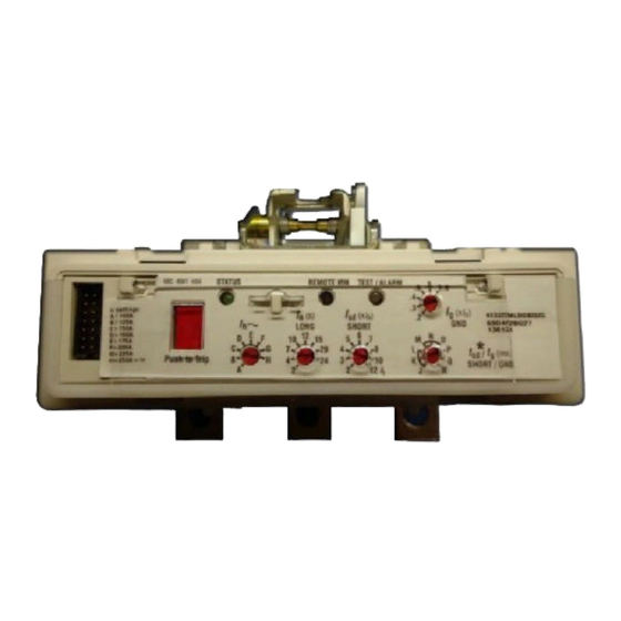
KES 310+ Electronic Trip Unit
Effective October 2013
Contents
Description
1. Trip Unit Installation . . . . . . . . . . . . . . . . . . . . . 2
2. Trip Unit Controls and Functions . . . . . . . . . . . 4
3. Neutral Current Sensor Installation . . . . . . . . . 6
4. 100% Rated K-Frame Breakers . . . . . . . . . . . . 7
Page
Advertisement

Summary of Contents for Eaton KES 310+
- Page 1 Instruction Leaflet IL012001EN Effective October 2013 Instruction Leaflet for the KES 310+ Electronic Trip Unit Contents Description Page 1. Trip Unit Installation ..... 2 2.
- Page 2 TRIP UNIT RETAINING SCREWS TORQUE 6 TO 8 LB-FT 3X ( 8 TO 10 N.m.) TRIP UNIT TEST PORT Figure 1. LOAD END Figure 4. TORQUE 18-23 LB-IN 8X (2.0-2.6 N.m.) Wires for optional features only. otee: Figure 2. Figure 5. EATON www.eaton.com...
- Page 3 Install any accessories, if required, using the appropriate instruction leaflet. Finish the installation of the 4-pole trip unit by following Figure 5. Retaining Screw (3 Places) Barrier Current Sensor Retaining Screw Trip Unit Secondary Winding Connector Figure 7. Alignment of Trip Unit and Current Sensor. EATON www.eaton.com...
- Page 4 The yellow and green wires that exit the right side of the g (ms) sd / SHORT / GND breaker are the common (C) and normally open (NO) of this relay. 12 I 68C 4081 H16 EATON www.eaton.com...
- Page 5 Three wires exit the breaker with the following color code and function: White/Black Stripe=Zone Out, White/Red Stripe=Zone otee: The RMM and High Load\GFA Alarm contacts are rated at 2A at 30 In, and Black=Common. VDC and 0.5A at 125 VAC. EATON www.eaton.com...
- Page 6 5.69 AT TOP 2.188 [55,58] [144,53] 12,70] 1/2" BOLTS (NOT INCLUDED) 2.25 [57,15] 1.188 1.17 [30,18] [29,72] 5.75 AT BASE 2.25 AT TOP [146,05] [57,15] 2.33 AT BASE [59,18] 2.91 AT BASE [73,91] Figure 10. Neutral Current Sensor. EATON www.eaton.com...
- Page 7 100% of the frame rating if used with CU only 90° C insulated wire and AL9CU terminals in an enclosure which measures at least 24” high x 15” wide x 6” deep. Ventilation is not required in an enclosure having these minimum dimensions. EATON www.eaton.com...
- Page 8 The information, recommendations, descriptions, and safety nota- tions in this document are based on Eaton’s experience and judg- ment with respect to Retrofitting of Power Breakers. This instruction- al literature is published solely for information purposes and should not be considered all-inclusive.


