Advertisement
Quick Links
Installation Instructions
Models SSD / SSD-INTL
System Status Display
INTRODUCTION
OPERATION
Controls and Indicators
P/N 315-034170-13
The Model SSD/SSD-INTL from
Siemens Industry, Inc., is an optional
FireFinder module that displays the
event status of a system remotely
from the PMI/PMI-2/PMI-3 (XLS),
FCM2041-U2 (Desigo Fire Safety
Modular), FCM2041-U3 (Cerberus PRO Modular). It has four 40 character alphanu-
meric LCD character lines, backlit upon status change or display toggling. This module
is supervised by the main panel and also has LEDs and an optional sounder to indicate
the status of the system. The SSD/SSD-INTL has the capability to store up to 1500
event messages and has pushbuttons to scroll through these events. Its display is
independent from the display on the PMI/PMI-2/PMI-3 (XLS), FCM2041-U2 (Desigo
Fire Safety Modular), FCM2041-U3 (Cerberus PRO Modular).
The following items are supplied with the SSD/SSD-INTL:
•
SSD mounting plate (P/N 300-034289) with the SSD-TB interface board
(P/N 515-034170)
•
8-pin wiring interface cable (P/N 555-134347)
•
SSD housing (P/N 195-134170) with an SSD-main board (P/N 557-034170)
•
Overlay—The SSD has one overlay, the SSD-INTL has three overlays.
-
SSD overlay (P/N 200-134290 in English)
-
SSD-INTL overlays (P/N 200-134754 in French, P/N 200-134755 in
Spanish, P/N 200-134756 in Portuguese)
•
4 screws to mount the housing to the mounting bracket (P/N 545-634442)
The SSD-INTL is used in applications where French, Spanish or Portuguese is the
primary language. It is identical to the SSD in all other ways, and will be referred to in
the remainder of this document as SSD.
The SSD has six LEDs and a sounder to indicate the status of the fire alarm panel.
The LCD indicates the state of a specific event. The SSD also has push buttons that
allow the user to scroll through the events list, control the sounder and acknowledge
events displayed on the LCD.
The SSD must be configured in the Zeus Programming Tool as Display only. Refer to
the Programming section on page 5 for information on configuring the system.
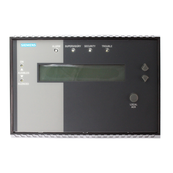
The front panel of the SSD contains 6 LEDs, 1 LCD display, up and down navigational
buttons and a Local Acknowledge button as shown in Figure 1.
ALARM
SUPERVISORY
SECURITY
ON
AUDIBLES
SILENCED
Figure 1
SSD System Status Display
Siemens
Siemens
Siemens Industry
Siemens
Siemens
Building
Building
Building
Building
Building T T T T T ec
ec
ec
echnologies Di
ec
hnologies Di
hnologies Di
hnologies Division
hnologies Di
TROUBLE
LOCAL
ACK
Industry, , , , , Inc.
Industry
Industry
Inc.
Inc.
Industry
Inc.
Inc.
vision
vision
vision
vision
Advertisement

Related Manuals for Siemens SSD


Summary of Contents for Siemens SSD
- Page 1 4 screws to mount the housing to the mounting bracket (P/N 545-634442) The SSD-INTL is used in applications where French, Spanish or Portuguese is the primary language. It is identical to the SSD in all other ways, and will be referred to in the remainder of this document as SSD.
- Page 2 ON-STEADY. Indicates that at least one unacknowl- edged alarm is present in the system. Siemens Industry, Inc. P/N 315-034170-13 Building Technologies Division...
-
Page 3: Down Arrow
See Figure 2. FIRST FIRST FIRST FIRST ALARM SECURITY SUPERVISORY TROUBLE MOST RECENT MOST RECENT MOST RECENT MOST RECENT ALARM SECURITY SUPERVISORY TROUBLE Figure 2 Event Priority Siemens Industry, Inc. P/N 315-034170-13 Building Technologies Division... -
Page 4: Pre-Installation
SSD mounting plate. Refer to Figure 4. S1 Option Select DIP Switch: S1-SW1: Set to ON if the SSD is the end of the PAIR A wiring (Style 4 only) S1-SW2: Set to OFF: Not Used S1-SW3: Set to OFF: Not Used S1-SW4: Set to OFF: Not Used Siemens Industry, Inc. - Page 5 R70 LCD Trimmer Adjustment (factory set): Turn to adjust the LCD contrast as required. If the SSD fails, the TROUBLE LED will flash at a fast rate, the sounder will pulse and no push buttons will respond. The PMI/PMI-2/PMI-3 (XLS), FCM2041-U2 (Desigo Fire Safety Modular), FCM2041-U3 (Cerberus PRO Modular) detects this failure as a non- responding module trouble condition.
- Page 6 Remove all system power before installation, first battery, then AC. (To power up, connect the AC first, then the battery.) Refer to Figure 5 for a typical wiring connection of Model SSD to the FireFinder-XLS/ Desigo Fire Safety Modular/Cerberus PRO Modular System.
-
Page 7: Installation
The wiring diagram in Figure 6 shows the connections from the SSD to the NIC-C and PSC-12. Refer to the NIC-C Installation Instructions, P/N 315-033240 and the PSC-12 Installation Instructions, P/N 315-033060 for additional wiring information. DO NOT USE DO NOT USE... -
Page 8: Electrical Ratings
Slightly bend the overlay to align and insert the 3 top tabs into the 3 corresponding slots in the top of the SSD Assembly. Press the overlay to the SSD assembly just beneath the cutout for the SSD display so that the adhesive from the strip on the overlay adheres to the SSD assembly. - Page 9 Cyber security disclaimer Siemens products and solutions provide security functions to ensure the secure operation of building comfort, fire safety, security management and physical security systems. The security functions on these products and solutions are important components of a comprehensive security concept.
- Page 10 Siemens Industry, Inc. Siemens Canada, Ltd. Document ID A6V10239126 P/N 315-034170-13 Building Technologies Division 1577 North Service Road East Florham Park, NJ Oakville, Ontario L6H 0H6 Canada...