Advertisement
Quick Links
NorthStar
™
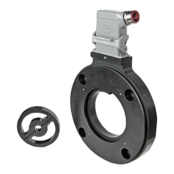
SLIM Tach ST85 Bearingless Encoder
Key Features
• Redesigned using our Revolutionary Sensor
Technology to provide a Large Air Gap of 0.060"
• Bearingless Design Mounts to 180 C-Face
Motors
• Dual C-Face Versions Available for
"Sandwich" Mounting
• Anodized Aluminum Housing with
Field-Serviceable Connector
• Single or Dual Isolated Outputs Available
SPECIFICATIONS
STANDARD OPERATING CHARACTERISTICS
Code: Incremental
Pulses per Revolution: 64-2048
Phasing Sense: A leads B for Counter-Clockwise
rotation (CCW) viewing encoder-mounted end
Quadrature Phasing: 90° ± 45°
Symmetry: 180° ± 54°
Index: Less than phase A/B pulse width
Number of Output Modules: Single or Dual
Redundant
ElECTRICAl
Input Voltage Requirement: 5-26 Volts DC
Current Requirement: 95 mA typical per sensor
module plus line driver load
Output Signals:
With Elec Option V: 5-26 V Line Driver, 150mA
With Elec Option 5: 5V Line Driver, 150mA
Frequency Response: 0 - 180kHz Data & Index
Electrical Immunity: 2kV ESD, Reverse Polarity,
Short Circuit
Connector: 10 pin industrial duty latching, sealed
NEMA 4 &12, IP65; MS connector or pig-tail
ElECTRICAl CONNECTIONS
Signal
Connector Pin Pigtail Cable
1
Common
B
2
A
3
Z *
4
No Connection
5
Vcc (5-26 VDC)
6
B
7
A
8
Z *
9
10
Shield
* Index (Z) optional. See Ordering Information
Encoder Installation Manual
brand
MECHANICAl
Max. Shaft Speed: 7,000 RPM
Mounting Configuration: 8.5" 180C face mount
for NEMA MG1 standards
Housing Material: Aluminum
Acceleration Rate: 3,600 rpm/sec max
Shaft length Required: 0.7" min
Allowable Shaft End-Play: ± 0.1"
Allowable Shaft Runout: 0.005" TIR
MS 3102E18-IT#
F
Black
Green
B
A
Blue
C
Violet
E
-
Red
D
Yellow
I
Gray
H
Orange
J
Braid
G
Conduit Box
1
5
3
7
-
2
6
4
8
-
ENVIRONMENTAl
Operating Temperature Range:
Standard: -40°C to +100°C
Optional: Extended, -40°C to +120°C
Storage Temperature Range: -40°C to +120°C
Humidity: to 100% RH
Shock: 300 G's Min.
Vibration: 20 G's @ 5-2000 Hz spectrum
CONTENTS
Specifications ........................Pg 1
Important ................................Pg 2
Mechanical Installation .........Pg 4
End of Shaft Installation .......Pg 7
Dimensions ..........................Pg 10
Ordering Information ...........Pg 10
EN 61326
Advertisement

Related Manuals for NorthStar SLIM Tach ST85


Summary of Contents for NorthStar SLIM Tach ST85
-
Page 1: Table Of Contents
NorthStar ™ Encoder Installation Manual brand SLIM Tach ST85 Bearingless Encoder Key Features • Redesigned using our Revolutionary Sensor Technology to provide a Large Air Gap of 0.060” • Bearingless Design Mounts to 180 C-Face Motors • Dual C-Face Versions Available for “Sandwich” Mounting EN 61326 • Anodized Aluminum Housing with Field-Serviceable Connector • Single or Dual Isolated Outputs Available SPECIFICATIONS STANDARD OPERATING CHARACTERISTICS MECHANICAl ENVIRONMENTAl Code: Incremental Max. Shaft Speed: 7,000 RPM... -
Page 2: Important
IMPORTANT INSTALLATION INFORMATION GENERAL GuIDELINES ELECTRICAL CONNECTIONS (cont.) In some cases, there may be more than one table or Encoders provide quality measurements and long the table may be broken into sections due to different life when common sense, care, and accurate align- output types. If so, refer to the information listed for ments are provided during installation. - Page 3 IMPORTANT INSTALLATION INFORMATION LED STATuS LIGHT: A multicolor LED Status light will indicate to the user FEATuRES (cont.) the overall condition of the encoder. The LED is built into the encoder and does not require any additional When encoders have a differential line driver, there wiring or power to activate it.
-
Page 4: Mechanical Installation
MECHANICAL INSTALLATION 4.0 Tighten (2) 1/2”-13 UNC to a nominal 85 1.0 Clean outer rim and surface of motor facing ft-lbs when cover option is PP. For other cover and shaft of paint, grease, dirt and other debris. options use all (4) 1/2”-13 screws 2.0 Remove housing from packaging 5.0 Slide Clamp wheel on to the shaft 6.0 Position the wheel such that its front surface... - Page 5 MECHANICAL INSTALLATION 7.0 Tighten (2) M5x0.8 screws to a 10.0 Pull the mating connector out and complete nominal 2.6 N-m. wiring per electrical connections table 11.0 Latch mating connector to the housing. 8.0 Tighten (2) 1/2”-13 Hex Bolt to secure the cover Installation is complete. 9.0 Grab mating connector, unscrew (4) mating connector screws.
- Page 6 MECHANICAL INSTALLATION Collet wheel option: a. Insert wheel adapter into the collet wheel, install (4) M4x0.7 screws (do not tighten com- pletely). b. Slide the wheel onto the shaft; align the adapter front surface with housing groove sur- face. c. Tighten the screws to a nominal of 2.24 N-m. Page 6...
-
Page 7: End Of Shaft Installation
END-OF-SHAFT WHEEL lNSTALLATION 1.0 Overview The ST8 Magnetic wheel assembly comes in two versions. “Through Shaft” and “End of Shaft”. The Through Shaft version allows the motor shaft to completely transit “through” the center of the magnetic wheel. The wheel is somewhat like a large collar around the shaft. - Page 8 END-OF-SHAFT WHEEL lNSTALLATION EOS Wheels G01 Wheel Assembly G06 Wheel Assembly Page 8...
- Page 9 END-OF-SHAFT WHEEL lNSTALLATION G08 Wheel Assembly G10 Wheel Assembly Page 9...
-
Page 10: Dimensions
Ordering Information To order, complete the model number with code numbers from the table below: Code 4: Wheel Bore Code 5: Termination Code 6: Electrical Code 1: Model Code 2: PPR Code 3: Index Code 7: Cover/Adapter Ordering Information ST8 Direct CC Flat No-Hole Cover 0064 B Conduit Box...