Table of Contents
Advertisement
Advertisement
Table of Contents

Subscribe to Our Youtube Channel
Related Manuals for Detnov CAD-250


Summary of Contents for Detnov CAD-250
- Page 1 CONFIGURATION GUIDE...
- Page 4 Revision control Revision Comment Date First edition. Software version 0.19.12 (27 Nov 2019) 09/04/2020 Updated layout. Software version 1.1.1. 16/06/2020...
- Page 5 If these criteria are not met, the control panel may be damaged, problems may arise during system start-up or the functioning of the system may be adversely affected. The CAD-250 control panel is certified to work under certain conditions; exceeding the working ranges of the control panel or inadequate conditions can lead to the warranty being voided.
-
Page 6: Table Of Contents
CONTENTS 1. INTRODUCTION ................8 1.1. Disclaimer .................8 1.2. Standards and compliance ............8 1.3. Required documentation ............8 1.4. Definitions ................8 1.5. About this manual ..............9 1.6. Before getting started .............10 1.7. Areas and zones ..............11 2. VESTA SYSTEM ARCHITECTURE..........12 2.1. Loops and devices ..............12 2.2. - Page 7 5. SETTINGS ...................22 7.4. Editing configuration entities ..........54 7.4.1. Description....................54 5.1. General ..................22 7.4.2. Defining and assigning sectorisation entities........54 5.1.1. Control panel description ..............22 7.4.3. Mode change in the sectorisation menu ..........55 5.1.2. Contact phone ..................23 7.4.4. Test mode .....................55 5.1.3.
-
Page 8: Introduction
The CE marking on this control panel indicates its compliance with Detnov pays special attention to the compatibility of the components the applicable directives and regulations of the European Community. and the integrity of the system in the long term; however, check any... -
Page 9: About This Manual
The definitions are classified according to the following levels: programming the CAD-250 fire alarm control panels from the control panel screen. This manual does not provide the required minimum Word... -
Page 10: Before Getting Started
1.6. BEFORE GETTING STARTED Please note that fire detection and alarm systems play an important role in protecting people and property. The design, installation, configuration and start-up require specific knowledge of the product and the design standards. There may be specific local rules and regulations. For the detection system to be effective, the protected building's spaces must be organised and grouped so that both the detection of a potential fire and the warning are accurate and allow an immediate response. -
Page 11: Areas And Zones
TS54-14. For complex systems, CAD-250 allows a subdivision level that is higher to the zone, the Areas. For the CAD-250 system, the zones are spatial subdivisions restricted locally by a single panel, whereas the areas can break this restriction and constitute subdivisions on the control panel network level. -
Page 12: Vesta System Architecture
The automatic detection elements, manual detection elements, manual call points, monitoring modules or output elements, such as sounders or control modules, are the devices that are connected to the CAD-250 control panels in a closed loop. The control panel allows open loop operation, but the use of this topology, whereby a single incident in the transmission lines can lead to the loss of protection in quite large areas, is not recommended. -
Page 13: Panel
2.4. PANEL The modular design of the CAD-250 control panel allows up to 3 modular components to be combined in a single structure of up to 4 sections or cabinets. This feature provides CAD-250 control panels with extraordinary versatility and power. As such, nodes or single control panels can be... -
Page 14: Initial Configuration
• The events view 3. INITIAL CONFIGURATION Control functions, such as: Before you do anything else, a series of basic steps must be carried • Control panel acoustic silencer out. • Sounder silencer 1. Define and obtain the physical sectorisation of the building, accord- •... - Page 15 Configuration steps With the systems already installed, it may be necessary to edit a loop unit due to updates or changes made in the facilities. For the loop unit functions: WORKING MODES - Special mode configuration ......Section 11.1, page 82 Section 11.1, page 82 General settings - Two-step delay configuration .......Section 11.2, page 87...
-
Page 16: User Level
3.1. USER LEVEL Access with a user access code. The user codes are generated from the SETTINGS menu, accessible from level 2 with the administrator password (see section 4.1 ADMINISTRATOR ACCESS). From this menu, it is possible to disable entities, view the event log, check certain configuration parameters, set the date or carry out a control panel indicator test. -
Page 17: Configuration Level
3.2. CONFIGURATION LEVEL From this level, it is possible to set all control panel parameters. For example, descriptions of all entities, operating modes, communications, network, etc. You can also view the status of all elements and their analogue values, or carry out an autosearch for the elements installed in each loop. -
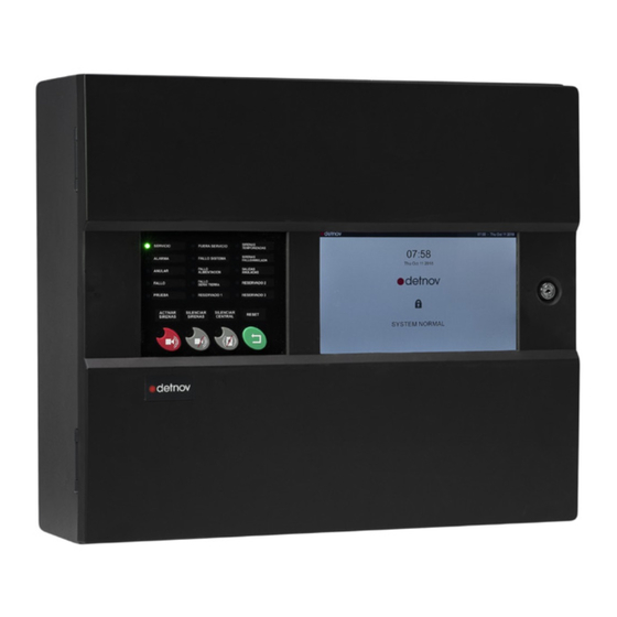
Page 18: Main Characteristics Of The Control Panel
Main interface of the CAD-250 control panel. panel, including the buttons, visual and audible indications and their PRINTER Only available on CAD-250-P: It allows you to obtain a behaviour. paper copy of the system's events. This device cannot be installed as an option. -
Page 19: General Leds
3.5. GENERAL LEDs 3.6. PRIMARY CONTROLS Function Symbol Description Colour/ Condition Description status ACTIVATE SOUNDERS Press the button to activate the sounders. EVACUATION SERVICE Green The control panel is powered Permanent ALARM MUTE SOUNDERS The fire alarm condition is active from any Press the button to silence the sounders. -
Page 20: Control Panel Configuration
4. CONTROL PANEL CONFIGURATION Tap the padlock icon on the touchscreen (��). By doing so, you will access the ACCESS SCREEN, requesting the access code and password. 4.1. ADMINISTRATOR ACCESS Depending on the password entered, certain configuration parameters will not be available to prevent improper use of the system. -
Page 21: Administrator Screen
4.2. ADMINISTRATOR SCREEN The administrator screen is divided into 6 different sections: Name Posit. Description MAIN MENU Left Categorises the sections. Loops - Sectorisation - Manoeuvres - Logs (history) - Network - Settings - Facility SUBMENU Right Classifies the options for each menu section. It is different for each section. -
Page 22: Settings
5. SETTINGS 5.1. GENERAL In this section, you will be able to establish basic configuration parameters for the control panel. To access these settings, press: SETTINGS(Main menu) > GENERAL (Submenu) Main View Submenu Main Menu 5.1.1. Control panel description SETTINGS(Main menu) > GENERAL (Submenu) > MISCELLANEOUS (Tab) This field defines the name of a control panel in the facility. -
Page 23: Contact Phone
5.1.2. Contact phone SETTINGS(Main menu) > GENERAL (Submenu) > MISCELLANEOUS (Tab) The contact phone will be shown in the EVENT MANAGER (see User Manual) when a FAULT is detected. To modify it, select the CONTACT PHONE field and a virtual keyboard will appear. -
Page 24: Date Selection
5.1.5. Date selection SETTINGS (Main menu) > GENERAL (Default submenu) > DATE AND TIME (Tab) This section defines the time and date of the control panel, which will be used when manoeuvres are programmed. To modify each field, just touch the required field and slide the field's scroll wheel until the required value is reached. -
Page 25: Screen Settings
5.1.6. Screen settings SETTINGS (Main menu) > GENERAL (Default submenu) > Screen (Tab) From this section of the settings menu, the following screen elements can be calibrated: Backlight. It allows you to adjust the screen brightness in order to adapt it to the ambient conditions. Left margin. -
Page 26: Versions
5.2. VERSIONS In this section, you can check the firmware and control panel versions, as well as update them from the external program for PC or from a pen drive. To access these settings, press: SETTINGS(Main menu) > VERSIONS(Submenu) Main View Submenu Main Menu The screen shows you all of the firmware versions the control panel... -
Page 27: Card Firmware
5.2.1. Card firmware The card tab shows a comparison of the versions you have installed and the ones that are loaded and ready to install. The available versions are loaded from the USB type A port on the control panel or from the SCD-250 configuration software. See the update from pen drive example in the following section or check the SCD-250 control panel configuration program manual. -
Page 28: Installation From The Usb Port
5.2.2. Installation from the USB port 2. To update the FIRMWARE, press INSTALL FROM USB. One of the easiest ways to update the CAD-250 is via the USB TYPE A port using a PEN DRIVE. Make sure that the PEN DRIVE is formatted as FAT32; it is not necessary for it to be empty. - Page 29 If the chosen facility contains various panels, you will be able to choose A window will ask you to confirm the FIRMWARE update. between the panels that comprise it. 6. Press the FIRMWARE button. 4. Press the Panel 1 button (1). Once you have selected the panel, the system will ask you to choose between updating the DATABASE, FIRMWARE and ALL.
-
Page 30: Users
5.3. USERS In this section, you can generate passwords to access the CAD-250 system and assign the corresponding access levels in each case. To access these settings, press: SETTINGS(Main menu) > USERS(Submenu) Main View Submenu Main Menu The CAD-250 system allows the creation of 1000 users with their respective access levels. -
Page 31: Advanced
5.4. ADVANCED By touching the PANELS field, you will be able to include a value from 1 to 4. Enter the corresponding value. In this section, you can set basic configuration parameters for the control panel, as well as engineer settings to facilitate start-up and configuration tasks. - Page 32 In the OTHERS tab, there are 3 slider buttons for facilitating start-up and maintenance tasks. Inactivity timeout: by deactivating this slider button, the control panel will always remain in the last access level and screen that you used. Always active by default, the control panel will return to the main screen if there is no activity and the access password must be re-entered in order to gain access.
-
Page 33: Connectivity
This gateway lets you access the control panel configuration or integrate CAD-250 into other platforms or applications. Please note that for integration with ModBus, you must configure and enable the ports from the menu:... -
Page 34: Printer
5.6. PRINTER Option Definition If your control panel model is the CAD-250-P, this submenu will be ENABLE ENABLES printing for all system events or for the event type selected, see table below available. To access the SETTINGS category, press: LOCAL ONLY If the control panel is networked, when you mark this option, it will SETTINGS(Main menu) >... -
Page 35: Logs (Event Log)
5.7. LOGS In this section, you can modify the type of event recorded by the control panel. To access these settings, press: SETTINGS(Main menu) > LOGS (Submenu) Main View Submenu Main Menu This menu provides a single configuration option. The ACTIVATION AS INCIDENT option allows all output actions to be recorded in the event log. -
Page 36: Test (Display Test)
5.8. TEST In this section, you will be able to establish basic configuration parameters for the control panel. To access these settings, press: SETTINGS (Main menu) > TEST (Submenu) Main View Submenu Main Menu This function allows verification of the mandatory indicator lights on the front of the control panel (see section 3.5) and the display's performance. -
Page 38: Loop Menu
6. LOOP MENU 6.1. DEVICES Navigation bar. Loop and number of devices in the loop Filters In this submenu, you can configure the devices connected to a loop individually. LOOP (Main menu) > DEVICES (Submenu) To see the LIST of devices in each loop: Press Loop (n) >... - Page 39 Under the navigation bar arrow keys are the status filter buttons. By touching the filter option, the device list will be limited to those whose condition matches the selected filter: ALARM: Devices in fire alarm condition. They may be detectors, buttons or inputs configured as fire zones.
-
Page 40: Device Information And Configuration
6.1.1. Device information and configuration From the device list and when selecting one of them, you will have access to its detailed fields, which will allow you to check or configure its operation. The navigation bar identifies the loop number and device that you are in currently. - Page 41 In the information and configuration menu, each device has an action and associated information bar, which will be longer or shorter depending on the type of device: Enabled: in line with the mode field in the device definition menu. By moving the button to the left, the device will be disabled. If the slider button is set to the right and is green, the device will be enabled.
-
Page 42: Addressable Value
6.2. ADDRESSABLE VALUE On the action bar, there are two options for filtering the elements to be viewed. From this submenu, you will see the addressable value of each device installed in the loop. • Type filter: allows you to filter by the type of device. •... - Page 43 By activating the THRESHOLD filter: 1. Devices with a value that is lower than the configured value will have an orange background. 2. Devices with a value that is the same as the configured value will Addressable have a yellow background. Type Values Definition...
-
Page 44: Outputs
6.3. OUTPUTS By touching the device, a warning and confirmation message will appear. From this submenu, you can activate each output in each loop. Exercise caution and make sure that users have been warned and LOOP (Main menu) > Outputs(Submenu) there is no risk of activating the output. -
Page 45: Autosearch
6.4. AUTOSEARCH When starting the system up for the first time, it should recognise the devices installed in the loops. You can perform this action automatically via the AUTOSEARCH function. LOOP (Main menu) > AUTOSEARCH (Submenu) Main View Submenu Main Menu By default, all devices are supplied ex-works without an address. - Page 46 Press , START to begin the search process. Alternatively, the button lets you select all of the loops or Autosearch summary delete the entire selection. Type and address A progress bar will be shown in the main view. Press , SAVE to update the database. Press , CANCEL to undo the proposed changes.
-
Page 47: Autocheck
6.5. AUTOCHECK The control panel will try to identify all of the loop's elements, firstly via the data transmission output and then via the reception side. It This is a support function for start-up. It lets you check the will check that both diagnoses match and will indicate any error in the communications on both sides of the loop. -
Page 48: Communication Quality
6.6. COMMUNICATION QUALITY This submenu provides statistical information on the quality of communications in the loop. To access this function, press: Summary from the start LOOP (Main menu) > COMMUNICATION QUALITY(Submenu) Main View Submenu Main Menu Loop reset This function is useful for identifying potential coupling issues in the The tool shows the failure percentage, as well as the total number loop line, inductions or the erratic behaviour of a component. -
Page 49: Address Programming
6.7. ADDRESS PROGRAMMING From this submenu, the address of a single device connected to the loop can be configured. To access it, press: LOOP (Main menu) > ADDRESS PROGRAMMING(Submenu) Main View Submenu Main Menu Before searching for a device in the installation, the address that corresponds to each of the devices must be configured. -
Page 50: Sectorisation
UNE 23007-14, as well as any sector regulations that may be applicable The modes establish the behaviour according to a hierarchical structure whereby the AREA is superior to the ZONE and this is superior to the DEVICE. CAD-250 organises the system structure into Entities. - Page 51 The behaviour due to the WORKING MODE of an AREA will affect the ZONES and the DEVICES of each one, but this does not happen the other way around: • If an AREA is DISABLED, the ZONES contained in that AREA will be also, as will the DEVICES contained in those ZONES.
-
Page 52: Display Controls
7.2. DISPLAY CONTROLS It allows the sectorisation tree of the ZONES hierarchy to be collapsed Projects with CAD-250 will have a complex structure with innumerable or expanded. entities configured. To make it easier to view the information and check it, there are 3 control buttons in the top margin of the main screen of the sectorisation menu. -
Page 53: Filters
7.3. FILTERS By touching the DESCRIPTION field, a virtual keyboard will appear for you to enter the required description on which the filter will act. This In addition to display controls, there are also segmentation list filters, entry is sensitive to upper and lower case. which let you filter by the following criteria: •... -
Page 54: Editing Configuration Entities
7.4. EDITING SECTORISATION ENTITIES 7.4.2. Defining and assigning sectorisation entities To edit an entity, all you need to do is touch it on the main panel, for From the sectorisation menu and from each entity, you can edit the example, zone 1. relationship with the entity immediately above. -
Page 55: Mode Change In The Sectorisation Menu
7.4.3. Mode change in the sectorisation menu From the pop-up menu for editing entities, touch the MODE field and the selectable options will be displayed. • Enabled • Test • Disabled It is not possible to configure the device entities in TEST mode as this mode is inherited from the configuration of superior entities. - Page 56 Enabled: in line with the mode field in the device definition menu. By moving the slider button to the left, the device will be DISABLED. If the slider button is set to the right and is green, the device will be ENABLED. It applies to all entity types. Location: by moving the button to the right, the device's LED indicator will be activated, allowing physical identification in the facility.
-
Page 58: Manoeuvres
The process of programming a manoeuvre involves first defining the The manoeuvre configuration on CAD-250 control panels is extremely event or events that must trigger the action and then associating the powerful and flexible. -
Page 59: Main Manoeuvres Menu
The EVENTS, inputs, can be distinguished according to: Their origin: • Local or network • Facility, panel, loop, area, zone, device, group or virtual module. Condition: alarm, fault, technical. Type: all, push-button, detector or inputs. Logic state: Normal or Rejected (if you select alarm, the condition will be valid if there is no alarm). -
Page 60: Configuring A Manoeuvre
8.2. CONFIGURING A MANOEUVRES To create a manoeuvre, press the ADD button. This action will give you access to the screen for editing the manoeuvre. Using the navigation bar, you can move from one manoeuvre to another in order to edit each one. The counter shows the number of the manoeuvre you are currently in. -
Page 61: Inputs For Manoeuvres, Events
8.2.1. Inputs for manoeuvres, events. 1. To add input or output events to the manoeuvre to be configured, touch the ADD button in the bottom margin of the main screen. The pop- up screen allows you to choose between: • an EVENT •... - Page 62 • Entity: shows the entity you are configuring. It is not editable. input condition is met. The CAD-250 will confirm the input if it meets all requirements in its Type condition: it allows you to ascertain that the input is true definition.
-
Page 63: Defining A Time Condition
manoeuvre. You see that there is an event defined, but there is no ACTION. Device configuration When you configure inputs on the device level, you must select the loop to which the device belongs. The navigation bar will show you the loop it is currently in and the number of devices in the loop. -
Page 64: Outputs For The Manoeuvres
8.2.3. Outputs for the manoeuvres To create an action associated with an event, go back to point 1 in the previous section, inputs for manoeuvres. 1. Press the ADD button in the bottom margin of the main screen. The pop-up screen gives you the option of choosing between generating an ACTION or an EVENT. - Page 65 Actions: Type Entity Activate the outputs. Element Dev. Dev. Action Panel Loop Area Zone Group Deactivate the outputs. type ACTIVATE Enable the entity. Sounders Disable the entity. Relays Test, sets the entity to test mode. Sounders Reset the entity. dev. Pulse activates the entity's outputs with a pulse width that can be Sounder 1 configured between 0-600 seconds (10 seconds by default).
- Page 66 The attached example describes a medium complexity manoeuvre that can be configured with CAD-250. The configuration options are extremely flexible, letting you create very complex manoeuvres. When you create manoeuvres, plan the scenarios well and avoid creating loops.
-
Page 67: Group Programming
8.3. PROGRAMMING GROUPS From this submenu, you can configure element groupings to facilitate the creation of complex manoeuvres beyond the zone and area structure. To access it, press: MANOEUVRES (Main menu) > GROUPS(Submenu) Main View Submenu Main Menu A specific group of elements may be required in different input or output rules. - Page 68 Creating a group Navigation bar No. of groups From the GROUPS submenu, the following elements appear on the main screen: Navigation bar: it lets you jump to the next page if the number of groups defined exceeds the screen capacity. Group list Group counter: it shows the total number of groups created.
- Page 69 4. Once you have defined the group, press the ADD ENTITY button. 5. CAD-250 will display a new configuration window with 3 tabs for selecting entities: • Area • Zone • Device Select the entity type that you require. Once you have chosen a type, you cannot include any other type of entity.
-
Page 70: Virtual Mode Programming
8.4. PROGRAMMING VIRTUAL MODULES From this submenu, you can establish intermediate states that are very Navigation bar No. of models useful for creating feedback or conditioned sequences. To access it, press: MANOEUVRES (Main menu) > VIRTUAL MODULES (Submenu) Main View Main Menu Submenu Virtual module list... - Page 71 1. To create a virtual module, press the ADD button. 2. A screen appears that lets you associate the virtual module number that will be assigned. The system shows the first available number. Touch the arrow keys to move the counter up or down.
- Page 72 The following configuration options for the quick buttons let you pin them on the screen, accessing them from the screen or hiding them on the standby screen: • Shortcut: if this is active, it indicates that the button will appear on the standby screen, you can pin up to 5 buttons.
-
Page 73: Virtual Module Status
8.5. VIRTUAL MODULE STATUS This submenu lets you view the status and activate the virtual modules. To access it, press: MANOEUVRES (Main menu) > VM STATUS (Submenu) Navigation bar Number of modules Main View Submenu Main Menu Virtual module number Module name Active module There is a navigation bar in the menu that lets you jump to the next screen if the number of elements created exceeds the screen capacity. -
Page 74: Logs
Submenu Main Menu CAD-250 has the capacity for up to 1,000,000 event logs. These logs are vital for reviewing the chain of events, understanding the causes and checking the deployment of actions after a potential fire alarm, fault or activation. - Page 75 Event list: list of events recorded since the last deletion of events. They are displayed consecutively and in order of occurrence. In the SUBMENU column, the filters per event type are available, Alarm, Fault, Technical signals, Test and Information. The system will not save the events of devices, zones or areas that are disabled.
- Page 76 Field Definition Event identifier, event sequence number. Date Date and time when the event occurred. Type Event typology, corresponds to the types of filter in the submenu ALARM Fire alarm events FAULT OR FAILURE Fault events of any system element TECHNICAL ACTIVATIONS Events caused by the activation of technical signals, which are not a fire alarm detection...
-
Page 78: Network
10. NETWORK 10.1. NETWORK CONFIGURATION This configuration lets you configure basic parameters for the network architecture. To access it, press: NETWORK (Main menu) > NETWORK CONFIGURATION (Submenu) Main View Submenu Main Menu This menu has the following configuration fields: Type: it has 3 configuration options. •... - Page 79 Node synchronisation To configure the network, it is preferable to have an IP connection to each node and to use the PC configuration software for the control panel. It is also possible to carry out the configuration manually from the control panel screen, but the process will be slower and more tedious.
-
Page 80: Network Filters
10.2. NETWORK FILTERS From this submenu, filter the information you want to view for the remaining network nodes in the current panel. To access it, press: NETWORK (Main menu) > NETWORK FILTERS (Submenu) Main Menu Main View Submenu Networked systems move a lot of information and it may not always be convenient, practical or even useful to try to show all the information for If you press the number field, the numerical keyboard will appear for all control panels that make up the system. -
Page 82: Facility
Configuration overlaps on the same entity are not permitted attention. with different sign modes. CAD-250 lets you create up to 2500 special modes for processing The most specific mode takes precedence, therefore, if an area is the detection signals adjusted to the activity. For example, it is possible... - Page 83 The special mode menu appears with the following elements: Navigation bar Number of modes Navigation bar: it lets you jump to the next page if the number of special modes defined exceeds the screen capacity. Special mode counter: it shows the total number of modes created. Add button: it starts the creation of a new mode.
- Page 84 You can generate a low sensitivity mode applicable to a daily fraction of time and a high sensitivity mode applicable to another fraction of time. Optical-heat: it is applied to detectors that have both technologies. It can adopt the following values: optical only, heat only or both.
- Page 85 Type of time lapse: this field lets you assign the time fraction to the mode in which the mode will be active. It accepts the following values: • Always. This is the default value. There is no interruption in the assignment of the lapse and it will always remain active unless a precedence criterion is applied.
- Page 86 Mode filters As special modes are incorporated, the monitoring of the types that have been created or the identification of those that are active may be complex. The filters located in the bottom part of this menu's main screen will help to carry out the inspection.
-
Page 87: Two-Step Delay
11.2. TWO-STEP DELAY From this submenu, configure the delay mode in automatic detection. To access it, press: FACILITY (Main menu) > TWO-STEP DELAY (Submenu) Main View Submenu Main Menu When a detector is activated, two function buttons appear on the control panel's main screen: Add time: It extends the waiting time by a value equal to the The two-step delay function lets you configure the reaction times... - Page 88 The activation of the number of incidents specified in the MAXIMUM ALARM DELAY and ENTITY TYPE fields will cancel the delays. • Maximum alarm delay: it is the number of active detectors for cancelling the delay. It can adopt values of between 2 and 10. If 2 is defined as the value for this field, following activation of the first detector, the reaction time counter will start and from the main screen, you will be able to extend the delay until the...
-
Page 89: Special Panel Configurations
11.3. PANEL CONFIGURATIONS The panel menu lets you configure the following elements: This submenu lets you adjust some useful modes in the start-up Enable relays. The deactivation of this slider button (grey) will process. To access it, press: prevent the activation of all relay outputs, the control panel and system control modules. - Page 90 PCB Sounder 2. The deactivation of this slider button (grey) will External power supply. The CAD-250 system supports up to 32 prevent the activation of the sounder 2 output on the main board. The loops on a single NODE. When implementing large systems, it may be slider button should normally be active.
-
Page 91: Special Loop Configurations
This submenu lets you adjust some loop functions. To access it, press: working environment. FACILITY (Main menu) > PANEL (Submenu) The CAD-250 control panel has a dirty chamber detection procedure. The control algorithm assesses the changes in the chamber's value, Main View... - Page 92 Open loop notification. Systems for protecting people establish mechanisms that guarantee the continuity of the systems in the event of faults. They also try to limit the effects of the systems by establishing design and application criteria. Detection systems limit the effects of a short-circuit fault or an open circuit in the transmission lines.
- Page 94 APPENDIX 1: Compatible devices and consumption Isolator External power Address Standby Alarm Reference Type Description consumption consumption switch supply HEAT.D DTD-210A 0.3 mA 3 mA Addressable thermovelocimetric detector HEAT.D DTD-215A 0.3 mA 3 mA Addressable high-temperature heat detector OPTICAL.D DOD-220A 0.3 mA 3 mA Addressable optical detector...
- Page 95 Isolator External power Address Standby Alarm Reference Type Description consumption consumption switch supply MAD-421-I 0.3 mA 1.5 mA Addressable 1-input monitor and control module with isolator switch. MAD-422 0.3 mA 1.5 mA Addressable monitor and control module with 2 relay inputs and 2 relay outputs MAD-422-I 0.3 mA...
- Page 96 Isolator External power Address Standby Alarm Reference Type Description consumption consumption switch supply MAD-472 0.35 mA 7 mA MAD-473 0.35 mA 7.5 mA Connection base with built-in sounder and addressable beacon. MAD-481 0.3 mA 1.5 mA Addressable control module with 1 voltage-free relay input of 240 Vac and 5 A.
- Page 100 CAD-250_MC_380_en_2020 b...
Need help?
Do you have a question about the CAD-250 and is the answer not in the manual?
Questions and answers